Joslyn Surgitron I 1260 User manual

Surge Protective Devices
Installation, Operation
and Maintenance Manual
PN 750-0111-001 B00
Surgitron I
Surge
PrOTeCTION
Joslyn
TM

2
Surgitron itM inStAllAtion, operAtion AnD MAintenAnce MAnuAl
Table of Contents
tnbpowersolutions.com/joslynsurge
Guide to Installation and Assistance ............................. 3
The Importance of Correct Installation ........................... 3
Warnings ................................................ 3
Before Installation .......................................... 4
System Configuration Verification ........................ 4
Environmental Condition Verification ...................... 4
Wiring Connection Diagrams .................................5-6
Single Phase 2-Wire ................................. 5
Split-Phase, 3-Wire 3-Phase, 4-Wire Wye .................. 5
3-Phase, 3-Wire Delta ................................ 5
3-Phase, 4-Wire High-Leg Delta ......................... 5
3-Phase, 3-Wire Corner Grounded Delta ................... 6
Conductor Routing ......................................... 6
Upstream Over-Current Protection Device ......................... 7
Electrical Connections ....................................... 7
Conductor Sizing ........................................... 8
Mounting ................................................ 8
Conduit Openings and Enclosure/Mounting Dimensions .............8-9
Connecting Form “C” Dry Contacts ............................. 10
Verification and Power Up ................................... 10
Troubleshooting .......................................... 11
Technical Assistance ....................................... 11
Return and Warranty Procedures .............................. 11
Warranty Statement ....................................... 12

3
Surgitron itM inStAllAtion, operAtion AnD MAintenAnce MAnuAl
The Importance of Correct
Installation
W A R N I N G !
THE SURGITRON ITM WARRANTY IS VOIDED if the unit is damaged as
a result of improper installation or the installer’s failure to verify the
following conditions prior to installation.
W A R N I N G !
HAZARDOUS VOLTAGES PRESENT: Improper installation or
misapplication may result in serious personal injury or damage to the
electrical system. Read the complete installation instructions before
proceeding with installation. Remove all power to the electrical panel
before installing or servicing the SPD.
W A R N I N G !
IMPORTANT SAFETY INSTRUCTIONS: All work must be performed by
licensed and qualified personnel. The electrical system must be properly
grounded in accordance with the U.S. National Electrical Code, state and
local codes or other applicable codes for this SPD to function properly.
This device is suitable for installation where the available short circuit
current is 10,000 rms symmetrical amperes up to 480VAC or less. For
countries outside of the US follow applicable electrical specifications for
the country the unit is being used in.
W A R N I N G !
This Statement is only applicable for TNCS grounded systems.
Check to ensure that a proper bond is installed between neutral and
ground at the transformer upstream from all 3-Phase Wye, 3-Phase High-
Leg Delta or split-phase device (See NEC Article 250). If the transformer
is not accessible, check the main service disconnect/panel for the N-G
bond. Lack of a proper bond will damage and void the warranty.
W A R N I N G !
Do not HIPOT the Surgitron I Series units or the electrical system to
which the Surgitron I Series unit is connected without disconnecting the
Surgitron I series units conductors including phases, neutral and ground.
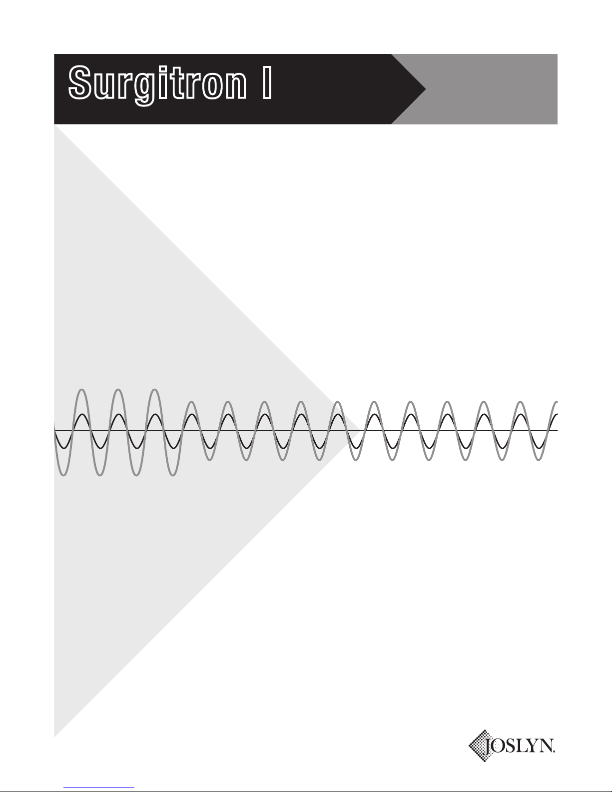
Thank you for choosing the Joslyn®Surgitron ITM Series Surge Protective Device
(SPD). We look forward to fulfilling your facilitywide surge protection needs.
Should you have questions about installing the Surgitron I series
please call Joslyn®Technical Support at 800.238.5000 or 804.236.3300
Monday through Friday, 8:00 a.m. to 5 p.m. (EST). Or, email us at
This manual provides guidelines for the proper installation of the Surgitron I series
of devices. Proper product selection and compliance with these guidelines will
help your new suppression system provide years of reliable service. If installers
are unsure about the facility electrical configuration or have other installation-
related questions, it is recommended they consult with a master electrician or
other qualified electrical professional.
When shortcuts are taken or installation procedures are not followed, the
Surgitron I series may become damaged or may not provide adequate protection.
It is extremely important to follow these installation procedures carefully.
Guide to Installation and Assistance

4
Surgitron itM inStAllAtion, operAtion AnD MAintenAnce MAnuAl
Confirm that the voltage(s) and service configuration shown on the product label are
consistent with the voltage and service configuration of the facility. A model number
is on the right side of the unit. Each model number corresponds to the configurations
printed in the table below:
Before Installation:
System Configuration Verification
Environmental Condition Verification Confirm that the environmental conditions are consistent with the following
ranges:
• Ambient Temperatures: Between -40° and +158°F (0 to 70º C).
• Relative Humidity: Between 5% and 95% non-condensing.
• Altitude: Less than 13,000 feet (4000m).
MODEL NOMINAL
VOLTAGE
L-N
VOLTAGE
RANGE
L-L
VOLTAGE
RANGE
CONFIGURATION
1260-45, -85 120 108-132 N/A 1-Phase, 2-Wire
+ Ground
1261-45, -85 230 207-253 N/A 1-Phase,2-Wire
+ Ground
1265-45, -85,
-85-M, -85-MN 120/240 108-132 216-264 1-Phase, 3-Wire
+ Ground
1266-45, -85 220/440 to
240/480 198-264 396-528
3-Phase,
3-Wire Delta,
Corner Grounded
1450-85 220/240 N/A 198-264 3-Phase, 3-Wire
Ungrounded Delta
1451-85 440/480 N/A 396-528 3-Phase, 3-Wire
Ungrounded Delta
1452-45, -80,
-85, -85-M,-
85-MN
120/240
High-Leg Delta
108-132 (A, C)
187-229 (B) 216-264
3-Phase, 4-Wire
+ Ground,
High-Leg Delta
1455-45, -80,
-85, -85-M,
-85-MN
120/208 108-132 166-250 3-Phase, 4-Wire
+ Ground
1456-45, -80,
-85, -85-M,
-85-MN
277/480 249-305 432-528 3-Phase, 4-Wire
+ Ground
1457-45, -80,
-85, -85-M,
-85-MN
230/400 207-253 360-440 3-Phase, 4-Wire
+ Ground
Available Options
Surge Counter Add suffix -S
Stainless Steel NEMA 4X enclosure Add suffix -4X
Dry Relay Contacts available on select models

5
Surgitron itM inStAllAtion, operAtion AnD MAintenAnce MAnuAl
Wiring Connection Diagrams
Figure 1
Single-Phase, 2-Wire
Models: 1260, 1261
Figure 2
Split-Phase, 3-Wire
Model: 1265
Figure 3
3-Phase, 4-Wire Wye
Models: 1455, 1456, 1457
Figure 4
3-Phase, 3-Wire Delta
Models: 1450, 1451
L
SPD
N
G
L1
L2
SPD
N
G

6
Surgitron itM inStAllAtion, operAtion AnD MAintenAnce MAnuAl
C A U T I O N !
The SurgitronTM I’s performance will be limited severely if the
conductors are (a) too long, (b) are of too small a wire gauge, (c) have
too many bends or (d) have sharp bends. For optimum performance
never exceed 10'.
Figure 5
3-Phase, 4-Wire High-Leg Delta
Model: 1452
Figure 6
3-Phase, 3-Wire Delta
Corner Grounded
Model: 1266
Conductor Routing
The factors listed above should be addressed during the design of an
installation to reserve a suitable place for the product next to its point of
connection to the electrical system. The selected mounting location should
allow for the shortest possible conductor runs and a direct route with a
minimum of bends. If bends are required, they should be sweeping bends
(12" radius). Do not make sharp 90° bends for appearance purposes because
they will severely decrease the effectiveness of the unit.
Binding or twisting conductors together using tie-wraps or electrical tape
increases the protection performance of the device.
SPD
SPD
SPD
BORANGE
C
A
N
G

7
Surgitron itM inStAllAtion, operAtion AnD MAintenAnce MAnuAl
C A U T I O N !
Prior to installation ensure the system configuration and voltage is
equivalent to the unit being installed.
Upstream Overcurrent
Protection Device
The Surgitron I has been listed to UL1449 as a Type 1 SPD. Type 1 SPDs
can be used in Type 1 or Type 2 SPD applications, which means that the
Surgitron I does not need to be connected behind an upstream Overcurrent
protection device and can be connected on either the line or load side of the
main service disconnect. The Surgitron I must be connected in parallel with
the electrical system. All units come standard with component-level over-
current fusing rated at 10,000 rms symmetrical amperes at up to 480VAC and
can be connected directly to the electrical distribution system bus without an
upstream over-current protection device (OCPD). If installing as a Type 2 SPD
the use of an external OCPD is recommended.
If the SPD is connected to a dedicated OCPD, a 60A breaker is recommended.
The advantage of using a dedicated over-current device for the SPD (even if
the upstream breaker is 200A or less) is that it allows the SPD to be de-
energized during service without disturbing the electrical service to the rest of
the facility.
Electrical Connections
Following all applicable National Electrical Code standards as well as state
and local codes, connect phase, neutral* and ground. Each phase conductor
is labeled (Phase A, B or C). The units come with compression box lugs. The
installer must provide the appropriate conductors. Ensure that the conductor
lengths are kept as short and straight as possible. On all high-leg delta
systems, the high-leg (208V L-N) must be connected to the Phase B of the
SPD. (color-coded orange according to NEC).
* The 3-Wire plus ground Delta SPD does not have a neutral conductor.

8
Surgitron itM inStAllAtion, operAtion AnD MAintenAnce MAnuAl
C A U T I O N !
Careful consideration must be made when selecting an area for
conduit entry. There are several components inside the enclosure
that may interfere with the conduit entry path, therefore, ensure
the path is clear of all objects before drilling. Damages caused by
installation errors are not covered under the product warranty.
See Figure 7 for conduit openings and enclosure dimensions.
Conductor Sizing Series Connecting: If the service conductors are AWG 2/0 or smaller than 70
mm2 , the protector can be series connected and brought directly through the
protector enclosure (the terminals are double lugged). This type of connection
is the better as there is no Ldi/dt voltage drop (additive to the protector’s
suppression voltage), as is associated with the shunt connection method of
installation. That is to say, the protection levels to connected equipment will be
better with this type of installation.
Shunt Connecting: The protector is connected in parallel to the service mains.
Keep the cables to the protector as short and straight as possible. The cable
lugs supplied with the protector will accommodate a cable size range of AWG
4 – 2/0 (20 – 70 mm2); a cable size of AWG 2 is normally used. The shunt
connections from the protector can be made directly to the main busses. If
no tap is available, the protector may be connected to a 60 Amp (minimum
recommended) circuit breaker or switch.
Mount the Surgitron I to the building structure using construction methods and
hardware appropriate for your site. Install the conduit and pull the conductors
as specified above or according to the engineer’s design.
If desired, punch holes at this time for the conduit or nipple or wait until
the Surgitron I is mounted to the building structure. Punch holes only in the
designated areas as shown in the following illustration.
Mounting
Conduit Openings

9
Surgitron itM inStAllAtion, operAtion AnD MAintenAnce MAnuAl
Figure 7:
Conduit Openings and
Enclosure/Mounting Dimensions
1260, 1261
1265
1266, 1452, 1455. 1456, 1457
6.00"
8.90"
10.75"11.50"
4.20"
13.50" 12.75"
8.00"
10.90"
5.20"
Ø.31" Mounting Hole
4 Places
6.20"
15.50" 14.75"
10.00"
12.90"
*
*
*
*
*
* Possible Locations for Conduit Holes
Metal NEMA 4 (IP66) Enclosure
*
*
*
*
*
*
Ø.31" Mounting Hole
4 Places
Ø.31" Mounting Hole
4 Places
* Possible Locations for Conduit Holes
Metal NEMA 4 (IP66) Enclosure
**
**
*
*
*

10
Surgitron itM inStAllAtion, operAtion AnD MAintenAnce MAnuAl
W A R N I N G !
It is recommended that the cover of the unit along with its associated
cabling be installed prior to applying power.
Connecting Form “C”
Dry Contacts
All units with -80, or -85 in the suffix come standard with two sets of Form
“C” dry relay contacts for the surge protective device status. These contacts
are for connection to a user-provided remote alarm and monitoring circuit. The
relay contacts are rated 125VDC/250VAC with maximum switching power of
300WDC/2,500VA AC.
For “Fail-safe” form A monitoring, connect the alarm leads to terminals 2 and
3. Terminals 2 and 3 will be closed during normal (Power ON) operation and
the protector is functioning properly. If the protector should fail contacts 2 and
3 will open and contacts 1 and 2 will close.
The installer must provide the appropriate raceway and wiring for the
monitoring circuit, observing the restrictions and conduit openings illustrated
in an earlier section of this manual. The install must route the monitoring
conductors to the terminal blocks on the door-mounted main monitoring
board. Route the wire to allow the door to be opened and closed properly.
Tighten screws on terminals to 3.5 in-lbs (0.4 Nm). This terminal block will
accept wire sizes #28AWG to #16AWG. #18 – #20 AWG is recommended.
Terminating wires with fork terminals suitable for #6 screws is also
recommended.
Verification and Power Up
When input power is present on all
phases, terminals “N/O” (Normally
Open) and “COM” are an open circuit
and terminals “N/C” (Normally Closed)
and “COM” are a closed circuit. The
contacts change state when the unit
has encountered failure to one or more
phases.
RE
M
OT
E
AL
AR
M
1
2
3
1
2
3
N/O 1
COM 2
N/C 3

11
Surgitron itM inStAllAtion, operAtion AnD MAintenAnce MAnuAl
INDICATION PROCEDURE
Troubleshooting Your system does not require scheduled maintenance. The unit’s heavy-duty
construction is designed to provide years of uninterrupted service. The unit
contains no serviceable parts.
One or more phase protection status
indicating lights are off, service
required indicating light is on, or
Form “C” alarm contacts have
changed state.
Verify that the input power feeding
the SPD is energized using a voltage
tester. If power is present, contact
factory for assistance:
800-238-5000.
Technical Assistance
Returns and Warranty Procedures
Our staff is ready to support you and answer any questions.
Monday through Friday, 8:00 a.m. to 5:00 p.m. (EST) at 800-238-5000
Units are warranted for a period of 5 years from date of purchase. In the event
that any module or subassembly within the SPD fails to perform as specified
during the warranty period, call our Technical Support at 800-238-5000.
A Return Material Authorization (RMA) number must be obtained from T&B’s
Customer Service department before replacement products can be shipped.
INFORMATION EXAMPLE
Model Number 1265-85
Serial Number 15478-0105-001
Date of Purchase January 2, 2005 (1st week)
Description of Failure LED Out
Desired Action from Joslyn Replace

12
Surgitron itM inStAllAtion, operAtion AnD MAintenAnce MAnuAl
Thomas & Betts Power Solutions, LLC, A Member of the ABB Group (“Seller”)
warrants that your Joslyn surge protective device (the “Product”), shall meet
applicable industry standards and specifications and be free from defects in
materials and/or workmanship. Should any failure of the Product to conform
to this warranty appear within the standard warranty period, Seller shall either
repair or replace the defective Product, or part thereof, upon return to Seller’s
manufacturing facility in Richmond, Virginia with transportation charges
prepaid. The applicable warranty period as outlined herein.
Seller shall have no liability under this warranty for any problems or defects
directly or indirectly caused by misuse of the Product, alteration of the Product
(including removal of any warning labels), accidents, or improper installation,
application, operation, or repair of the Product.
THIS WARRANTY REPRESENTS THE ENTIRE WARRANTY OF SELLER. ALL
OTHER WARRANTIES, EXPRESS OR IMPLIED, ORAL OR WRITTEN, INCLUDING,
BUT NOT LIMITED TO, THE WARRANTIES OF MERCHANTABILITY AND FITNESS
FOR A PARTICULAR PURPOSE ARE HEREBY DISCLAIMED.
The liability of Seller under this warranty is expressly limited to the
replacement or repair of the defective part thereof, at Seller’s sole option.
IN NO EVENT SHALL SELLER BE LIABLE FOR SPECIAL, INCIDENTAL, OR
CONSEQUENTIAL DAMAGES OF ANY KIND OR CHARACTER, NOR SHALL
SELLER’S LIABILITY EVER EXCEED THE PURCHASE PRICE PAID FOR SUCH
DEFECTIVE PRODUCT.
This warranty is not transferable and may only be enforced by the sole
purchaser. Claims under this warranty must be submitted to Seller within
thirty (30) days of discovery of any of Seller’s product defect.
Warranty Period
Surgitron ITM Series (AC) 45, 80, 85
(E.g. 1455-85-MN)
5 Year
© 2015, Thomas & Betts Power Solutions, LLC. • Thomas & Betts Power Solutions, LLC., is a wholly owned subsidiary of Thomas & Betts Corporation.
JoslynTM is a trademark of Thomas & Betts International, Inc. • Specications are subject to change without notice. • Visit our website for latest revisions.
Thomas & Betts Power Solutions
5900 Eastport Blvd. • Richmond, VA 23231-4453 USA
Tel: (804) 236-3300 • Toll free: (800) 238-5000 • Fax: (804) 236-4841
tnbpowersolutions.com/joslynsurge
PN 750-0111-001 B00 082715
Model #
Date of Purchase
Date Installed
Installer
Warranty Statement
This manual suits for next models
9
Table of contents
Other Joslyn Surge Protector manuals
Popular Surge Protector manuals by other brands

ABB
ABB TPME Series Installation, operation and maintenance manual

Eaton
Eaton BRSURGECSA Series Installation and operating guide

ASCO POWER TECHNOLOGIES
ASCO POWER TECHNOLOGIES 277 Installation & operation manual

Leviton
Leviton 57000 Series installation instructions

CyberPower
CyberPower 1030HT Specification sheet

Radio Shack
Radio Shack 61-2433 owner's manual