Tsun TSOL-B100E-S User manual
- 1 -
TSOL-B100E-S

- 1 -
Content
CHAPTER 1 SAFETY PRECAUTIONS .................. - 2 -
1.1 SAFETY INSTRUCTIONS..................................... - 2-
1.2 EXPLANATIONS OF SYMBOLS ................................ - 3-
1.3 EMERGENCY SITUATION.................................... - 4-
CHAPTER 2 PRODUCT INTRODUCTION ............... - 5 -
2.1APPLICATION SCOPE OF PRODUCTS........................... - 5-
2.2 SPECIFICATION FOR PRODUCT MODEL ........................ - 5-
2.3 DATASHEET.............................................. - 6-
CHAPTER 3 INSTRUCTIONS FOR INSTALLATION ...... - 7 -
3.1 ITEMS IN THE PACKAGE .................................... - 7-
3.2 INSTALLATION POSITION ................................... - 8-
3.3 MOUNTING PROCEDURE .................................. - 10 -
CHAPTER 4 ELECTRICALCONNECTION ............. - 14 -
4.1 SPECIFICATIONS FOR ELECTRICAL INTERFACE ................ - 14 -
4.2 SLAVE CONNECTION ...................................... - 15 -
4.3 COMMUNICATION INTERFACE .............................. - 17 -
4.4 INSTALLTHE RIGHT COVER ................................ - 18 -
CHAPTER 5 DEBUGGING INSTRUCTIONS ............ - 19 -
6.1TRANSPORTATION........................................ - 19 -
6.2 STORAGE............................................... - 19 -
CHAPTER 7 CONTACT US........................... - 20 -

- 2 -
Chapter 1 Safety Precautions
The User Manual describes system configuration and detailed procedures for
installation, operation and maintenance of TSOL-B100E-S Series Inverter Battery.
However, this manual does not include any information about inverters that the
battery may be applied to. Please read the User Manual before using this product.
1.1 Safety Instructions
DANGER
•Do not expose the battery to temperatures in excess of 45°C.
•Do not subject the battery to any strong force.
•Do not place the battery near a heat source, such as direct sunlight, a fireplace.
•Keep inflammable and explosive dangerous items or flames away from the battery.
• Do not soak the battery in water or expose it to moisture or liquids.
WARNING
•Only qualified personnel who has full knowledge of local safety regulations and local
standards on battery can install, maintain, retrieve and process this product.
•TSUNESS shall not be liable for any loss or warranty claims arising from any unauthorized
change of product which may cause fatal injury to the operator, third party or equipment
performance.
•For personal and property safety, do not short-circuit the positive (+) and negative (-)
electrode terminals.
CAUTION
•Do not modify or change any components in the battery.
•Risk of damage due to improper modification
NOTICE
•During installation of the battery , circuit breaker must be disconnected from the battery
pack wiring.
•The battery can only be used as a set with TSUNESS ACU series AC Coupled Unit,
otherwise it cannot be used normally.
- 3 -
1.2 Explanations of Symbols
Symbol
Description
Dangerous electrical voltage
The device is directly connected to public grid, thus all work to
the battery shall only be carried out by qualified personnel.
No open flames
Do not place or install near flammable or explosive materials.
Danger of hot surface
The components inside the device will release a lot of heat
during operation. Do not touch metal plate housing of the
inverter during operating.
Attention
Install the product out of reach of children
An error occurred
Read the usage manual to troubleshoot problems
This device SHALL NOT be disposed of in residential waste
Please go to Chapter six “Battery maintenance” for proper
treatment.
CE Mark
The device is in compliance with Low Voltage Detective and
Electromagnetic Compatibility.
Recyclable
- 4 -
1.3 Emergency situation
Despite of its careful and professional protection design against any hazard results,
damage of the battery may still occur. If a small amount of battery electrolyte is
released due to a serious damage of the outer casing; or if the battery explodes due
to not being treated timely after a fire breaks out nearby, and leaks out poisonous
gases such as carbon monoxide, carbon dioxide and etc., the following actions are
recommended:
1)Eye contact: Rinse eyes with a large amount of running water and seek
medical advice
2)Contact with skin: Wash the contacted area with soap thoroughly and seek
medical advice
3)Inhalation: If you feel discomfort, dizziness or vomiting, seek medical
advice immediately.
4)Use Heptafluoropropane (FM-200) or carbon dioxide (CO2) fire
extinguisher for battery fire, If a fire breaks out in the place where the battery pack
is installed
5)Use an ABC fire extinguisher, if the fire is not caused by battery and not
spread to it yet.
Warning
•If a fire has just occurred, try to disconnect the battery circuit breaker and cut
off the power supply first, but only if you can do so without endangering
yourself.
•If the battery is on fire, do not attempt to extinguish the fire and evacuate the
crowd immediately.

- 5 -
Chapter 2 Product Introduction
2.1 Application Scope of Products
The battery is applied to domestic photovoltaic storage system. The battery is built
eternally with a battery management system (BMS), which is used to ensure
efficiency of the battery and to avoid phenomena of overcharge or over-discharge.
The battery employs modular design for easy installation and wiring, and can be
used by up to 3 parallel devices. Battery is also called slave machine in the
following text.
Figure 2.1 outside overview
2.2 Specification for Product Model
TSOL –B100E –S
①②③
①TSOL of the brand.
②Energy capacity of battery XXAh,for instance, 100 means 100Ah.
③S means standard voltage of 48V.

- 6 -
2.3 Datasheet
TSOL-B100E-S
Type
TSOL-B100E-S
Electrical Characteristics
Total Energy Capacity[Wh]
5120
Usable Capacity [Wh]
4600
Rated Voltage [V]
51.2
Voltage range [V]
42~58.4
Depth Of Discharge[DOD]
≤90%
Cycle Life
≥4000
Max.Charge Current [A]
60
Max.Discharge Current [A]
60
Physical Parameters
Battery Type
Lithium ion
Communication
CAN
Operating Temperature Range
0°C~50°C
Cooling Method
Natural Convection
Ambient Humidity
0-95% Non-condensing
Ingress Protection
IP65
Dimensions[H*W*D][mm]
410*650*186
Weight [kg]
50
Standard Warranty [Year]
5(Battery 4000 Cycle)
Applicable Standard
UN38.3、IEC62619

- 7 -
Chapter 3 Instructions for installation
3.1 Items in the package
Battery pack
Wall bracket
mounting bolts set *6
Cables
Ethernet cable&RJ45 plug
User Manual
- 8 -
3.2 Installation Position
3.2.1 The battery size shown as follows
186
410
650
Figure 3.1 TSOL-B100E-S External view and dimension
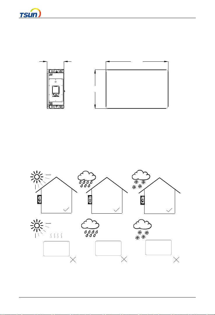
3.2.2 Installation Position
This device is cooled by natural convention and suggests an indoor installation or
an installation under a sheltered place to prevent the battery from exposure to
direct sun, rain and snow erosion.
Figure 3.2 Mounting Method
- 9 -
3.2.3 Mounting Method
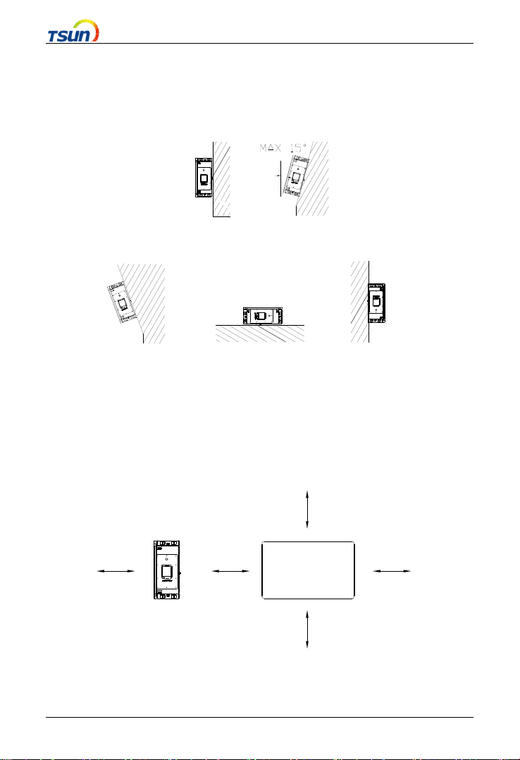
A vertical mounting is recommended and the battery accepts backwards by
Max.15°. Never mount the battery horizontally or upside down.
√ √
× × ×
Figure 3.3 Mounting method
Please make sure the battery pack is at all times exposed to the ambient air. Poor
air circulation will affect the performance of internal electronic components and
shorten the service life of inverter.
50CM
50CM 50CM
0CM 0CM
Figure 3.4 Installation position

- 10 -
3.3 Mounting Procedure
3.3.1 Positioning the drilled holes for bracket
The battery uses free-standing installation and its position is determined by the
drilled holes of bracket,Unit: mm.
Figure 3.5 Bracket for TSOL-B100E-S (Slave machine)
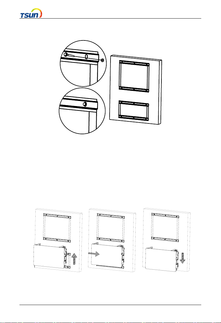
Make sure that the wall is capable of mounting screws and of supporting the
weight of the battery pack before installation. Mark the location of bracket's holes
on the wall and drill the holes. Then use a rubber hammer to drive screws into the
holes.
Figure 3.6 Bracket for TSOL-B100E-S (Slave Machine)

- 11 -
TSOL-ACU3.0K is a master machine while TSOL-B100E-S is a slave machine.
To ensure the installation of the device, the distance between master and slave
machine, slave and slave machine shall at least meet the following requirements:
Figure 3.7 distance between brackets
- 12 -
Fix the brackets in the marked position with hex screws。
Figure 3.8 mounting the brackets
During installation of the device, please install the slave machines first then the
master machines, in order to avoid a failure of installation due to a lack of space
between the master machine and the salve machines. Carefully mount the device
onto the brackets and make sure the bottom of the device is attached to the
brackets.

- 13 -
Figure 3.9 Installation of the master and slave machines
One master machine can be matched with up to three more batteries. During the
installation of the project, it is necessary to consider whether space shall be
reserved to add new battery packs in the future. The expansion diagram is as
follows.
Figure3.10 Batteries Expansion Diagram
- 14 -
Chapter 4 Electrical Connection
4.1 Specifications for Electrical Interface
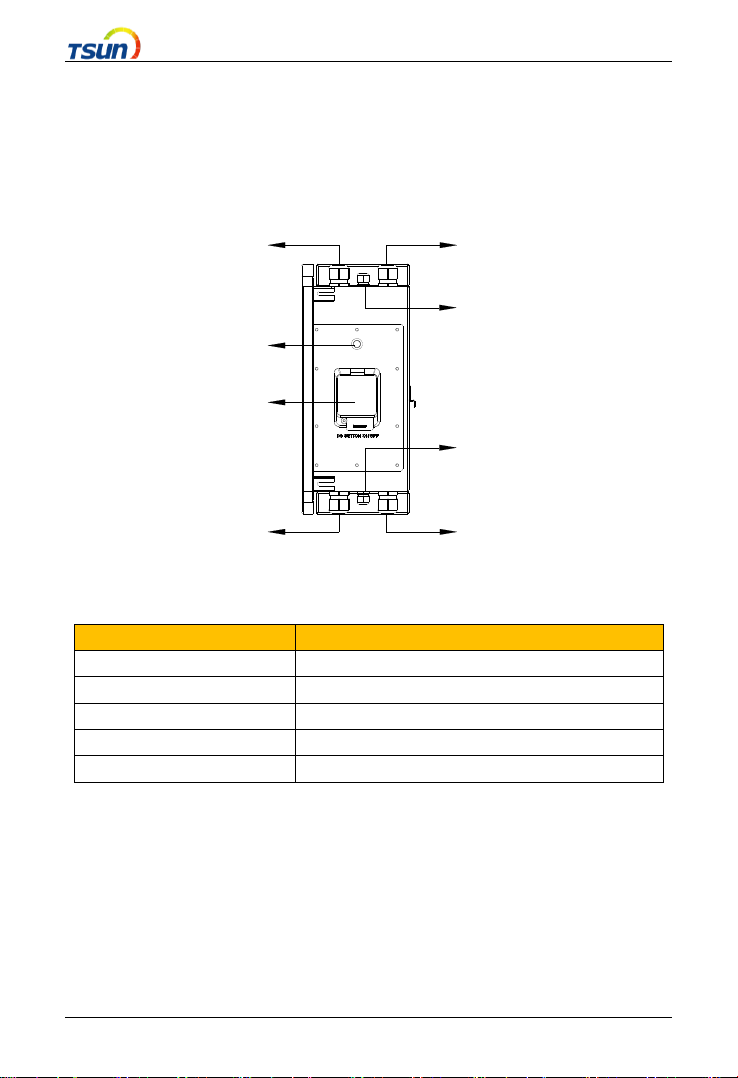
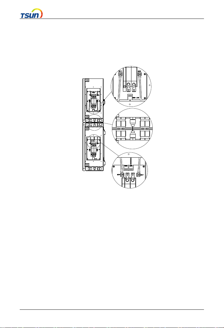
A
B
CE
D
c
d
e
Figure 4.1 Interface
Code
Name
A
BMS switch
B
Battery switch
C、c
BAT+port
D、d
BMS LINK port
E、e
BAT-port
Chart 4.1 Interface instruction
- 15 -
4.2 Slave connection
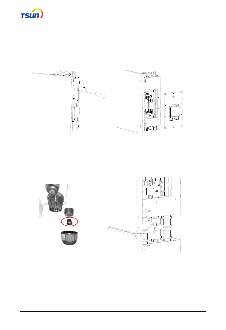
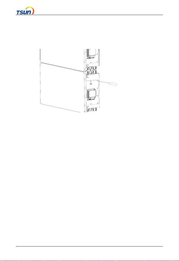
Make sure that the circuit breaker is off, remove the right wiring cover screw and
pull out the BMS switch cable then place the cover aside.
Figure 4.2 removing wiring cover
Remove the flange nut head counterclockwise, and remove it when there is a hole
plug, as shown in the figure below. Then pass the original cable through the
waterproof jacket.
Figure 4.3 Threading diagram
- 16 -
Only 3 cables are required (BAT+-BAT, BAT--BAT-, LINK-LINK) to connect a
slave. Be careful when connect. Do not reverse the positive and negative terminals.
Figure 4.4 Connection diagram

- 17 -
4.3 Communication interface
Take out the Ethernet cable fromthe battery packaging. Note: First pass the cable
through the waterproof jacket and then crimp the RJ45 plug.
Figure 4.5 Interface definition
Code
Name
1
blank
2
blank
3
blank
4
blank
5
blank
6
blank
7
RS485A
8
RS485B
Chart 4.2 interface pin description
Attention
•Please use the original matching battery cable
•Do not connect one battery to two inverters at the same time
•The waterproof sheath must be tightened after wiring to prevent rain
water from entering the interior
- 18 -
4.4 Install the right cover
Use the M4 screw originally removed to lock the cover plate. Torque is
recommended 14kgf.cm.
Figure 4.6 Install the right cover

- 19 -
Chapter 5 Debugging Instructions
System commissioning
After the wiring is completed, please refer to the ACU series manual for system
operation.
Note: Turn on the battery switch and BMS switch when using the battery.
Chapter 6 Battery maintenance
6.1 Transportation
Lithium batteries are dangerous goods. Passed the test of UN38.3, this product
meets the transportation requirements for dangerous goods for lithium batteries.
After the installation of the battery on site, the original packaging (contains the
lithium battery identification) should be kept. When the battery needs to be
returned to the factory for repair, please pack the battery with the original
packaging to reduce unnecessary trouble.
6.2 Storage
After purchasing the battery, please store it with following instructions:
1) Please store it in a dry and ventilated environment, keep it away from
heat sources;
2) Please keep it in an environment with storage temperature as -20 °C ~
50 °C, humidity <85% RH;
3) For long-term storage (>3 months), please put it in an environment with a
temperature of 18 °C to 28 °C and a humidity of < 85% RH;
4) The battery should be stored in accordance with the storage requirements
Table of contents


