MRMC MRMC-1488-00 User manual

ii
AFC (MHC) Quick Start Guide
QSG Product Code: MRMC-1488-00
Products Covered: MRMC-3000-217-00, MRMC-3000-219-00,
MRMC-1014-02-026-02-08-01
Modification Date: 5 November 2020
© 2020 Mark Roberts Motion Control Ltd. ®All rights reserved.
No part of this publication may be reproduced, transmitted, or translated
by any means — graphical, electronic or mechanical — including
photocopying, recording, taping or storage in an information retrieval
system, without the express written permission of Mark Roberts Motion
Control.
Although every care has been taken to ensure that the information in this
document is accurate and up to date, Mark Roberts Motion Control
continuously strives to improve their products and may make changes to
the hardware, firmware, and software described in this document. Mark
Roberts Motion Control therefore cannot be held responsible for any
error or omission in this document.
All product names mentioned herein are the trademarks or registered
trademarks of their respective owners.
Contact information
Mark Roberts Motion Control Ltd.
Unit 3, South East Studios
Blindley Heath
Surrey
RH7 6JP
United Kingdom
Telephone: +44 (0) 1342 838000
Web: www.mrmoco.com
www.mrmocorentals.com

AFC (MHC) Quick Start Guide
iii
AFC (MHC) Quick Start GuideAFC (MHC)Quick Start Guide
Contents
Chapter 1 Quick Start..................................................................... 1
Safety........................................................................................1
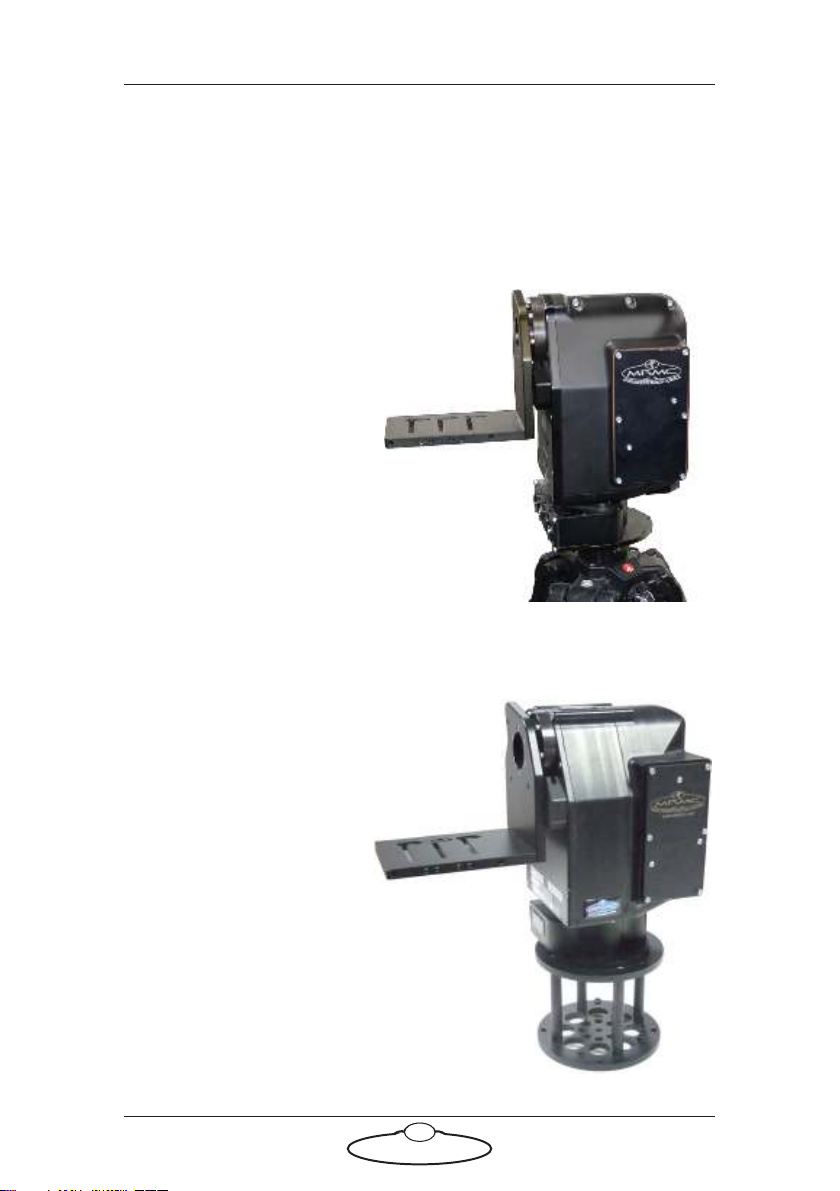
Overview ................................................................................. 1
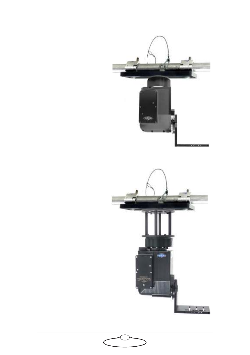
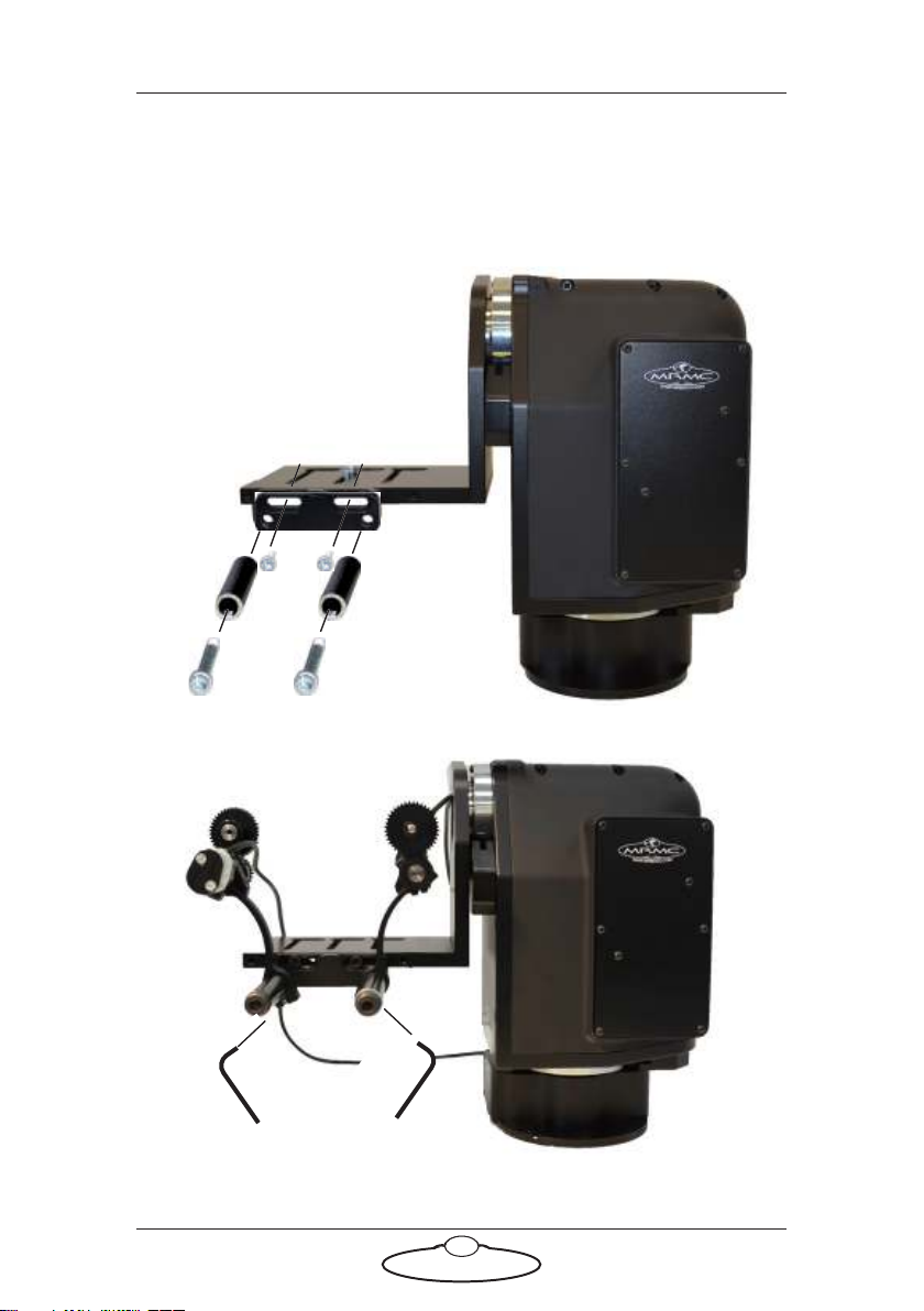
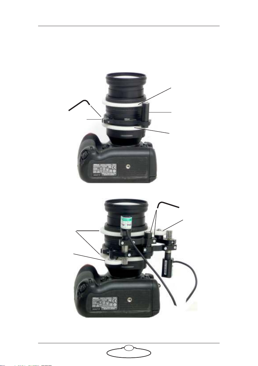
Setting up the hardware ........................................................2
Connecting the cables .........................................................10
Video camera example ...............................................10
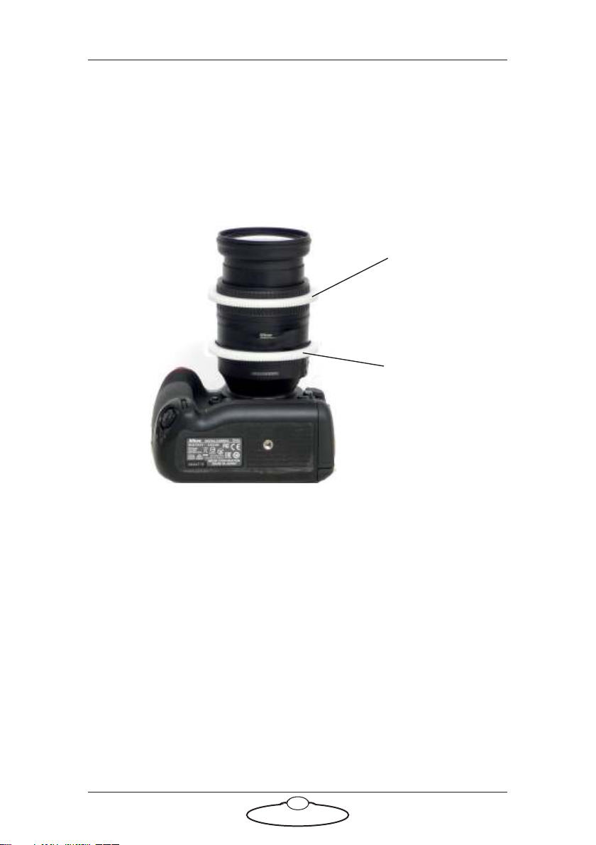
DSLR camera example ...............................................12
Your first session ..................................................................14
Subsequent sessions.............................................................16
Appendix 1 Troubleshooting........................................................... 18
Typical symptoms, causes, and actions .............................18
Working with Local Area Networks..................................18
Introduction to LAN addresses ................................19
Appendix 2 AFC Back Panel ........................................................... 23
Connector summary............................................................23
Panel AFC 100S with Slip Ring
(MRMC-3000-219-xx )..............................................24
Panel AFC 100 without slip rings
(MRMC-3000-217-xx)...............................................28
Panel AFC 180S with Slip Ring
(MRMC-1014-211-xx )..............................................30
Connector pin-out information.........................................33
12V Out connector (small DC jack) ........................33
12V Out connector (small resetable DC jack)........33
12V Out connector (large 4-way XLR)....................33
Video connector..........................................................34
Video Sync connector ................................................34
Trigger connector (standard trigger out) ................35
Serial (digital) lens connector for internal servo
LCMs ............................................................................35
Focus, Zoom, Iris lens connectors for external
servo LCMs..................................................................35
Stepper Axis connectors for external stepper
LCMs ............................................................................36
Power 24V connector.................................................36
Power 48V connector.................................................37

AFC (MHC) Quick Start Guide
1
AFC (MHC) Quick Start GuideAFC (MHC)Quick Start Guide
Chapter 1 Quick Start
Safety
•Do not use around flammable gas. All electrical equipment can
generate sparks that can ignite flammable gas.
•The head has powerful motors that can pinch, so take care not to get
your hands trapped in the head or cabling.
•Keep the equipment dry. The system has not been made
weatherproof. Do not use with wet hands.
•Keep cables tidy. Use cable ties to keep them out of harm’s way. If
you have a head with slip rings then make use of them; avoid
running any cables between the base and the rotating head or
camera.
Overview
Thank you for using the AFC robotic camera head from Mark Roberts
Motion Control (MRMC). The AFC head is an Accurate, Fast, and
Compact head designed for reliable day-in, day-out use in professional
studio and Outside Broadcast environments. The versatility of the AFC
head makes it suitable for live action, stills, and time-lapse applications.
The AFC Head and lens motors are controlled from devices running
Multi-Head Controller (MHC) software, Flair motion control software or
API over Ethernet. This manual describes using AFC with MHC only.
You can use the Ethernet connection on the AFC head to connect directly
or remotely to a PC running MHC by MRMC.

AFC (MHC) Quick Start Guide
2
Setting up the hardware
1. Mount the AFC head onto your choice of support, such as a
heavy-duty tripod or metal plate.
More information on mounting sockets and dimensions can be
found in Appendix 3 Specifications.
Example: AFC head
mounted directly onto
tripod with single
3/8-16 tripod
mounting bolt:
Example: AFC head
mounted on an
optional riser mounted
on a table, to give the
head more height and
Tilt clearance. Further
details are on page 43.

AFC (MHC) Quick Start Guide
3
Example: AFC head
underslung and
directly mounted onto
scaffolding plate.
Further details are on
page 45.
For notes on zeroing
the axes when using an
underslung
configuration, see page
16.
Example: AFC head
underslung and
mounted onto riser
which is, in turn,
mounted onto a
scaffolding plate.
Further details are on
page 46.

AFC (MHC) Quick Start Guide
4
2. If you are using serial (digital) lens then skip this step and go on to
step 3 on page 7.
If you are using external Lens Control Motors (LCMs) for focus and
zoom and possibly iris, then these are ordinarily configured in MHC
to suit your lens specifications. Set these up now as follows:
2.1 Install the large gears onto the focus, zoom, and iris rings of
your lens, as applicable.
The relative position of the rings depends on the make and
model of the lens.
Lens gear
Lens gear
(Zoom)
(Focus)

AFC (MHC) Quick Start Guide
5
2.2 For head-mounted LCMs, bolt the mounting rods onto the
head, then mount the LCMs onto the rods in approximately
the correct position. You can fine-tune the position later:
Matte
bars

AFC (MHC) Quick Start Guide
6
2.3 For lens-mounted LCMs, attach the mounting ring onto the
lens so it does not interfere with the focus, zoom, or iris rings,
then mount the LCMs onto the rod, making sure that the LCM
gears mesh firmly with the lens gears:
Mounting ring
Mounting rod
Lens gears
LCM gear
LCM gear
Lens gear
Lens gear
(Zoom)
(Focus)

AFC (MHC) Quick Start Guide
7
3. Place the camera on the platform, move the camera forward or
backward to balance the platform in Tilt, then insert the camera
mounting bolts under the platform and into the bottom of the
camera housing and tighten firmly.
Video camera,
Overslung
The camera and the lens MUST be carefully balanced on the platform.
One way to check this is: with the head powered off and the camera and
lens attached and screwed to the platform, the camera should be able to
balance without further assistance. If you find the lens drops down, then
the lens is too heavy. To mount heavier cameras and lenses, see balanced
offset platform on page 40.
Video camera,
Underslung

AFC (MHC) Quick Start Guide
8
4. If you are using head-mounted LCMs, adjust their position on the
rods so that the LCM gears mesh firmly with the lens gears.
DSLR camera

AFC (MHC) Quick Start Guide
9
Notes

AFC (MHC) Quick Start Guide
10
Connecting the cables
Video camera example
AFC head with BCST 043 panel, BCST 036 base, GV LDX Compact video
camera, Fujinon Digipower A22x7.8BERD-S28B Serial (digital) Lens
Control Motors, and Windows PC running MHC.
Power DC in
VIDEO
HD SDI (A)
Rear view
Front view
BCST MDL 013 panel
Serial Lens
Control Motors
SERIAL
ETHERNET
LENS
ETHERNET
12V OUT
REF
SYNC

AFC (MHC) Quick Start Guide
11
The controller can be any MRMC joystick such as the Broadcast Panel,
Mini USB Joystick, USB LFP Controller, or Xbox Joystick connected to
PC with MHC Motion Control Software.
24V 5A
Attach the
power cables
last.
SYNC
POWER 24V
VIDEO OUT
ETHERNET
PC running MHC
Motion Control Software

AFC (MHC) Quick Start Guide
12
DSLR camera example
AFC head with BCST 060 panel, BCST 062 base, Nikon D4s camera,
external Lens Control Motors, and LFP controller.
TRIGGER
TRIGGER
12V OUT
RESETABLE
12V IN
HDMI
HDMI
VIDEO
SDI
12V OUT FOCUS
ZOOM
Rear view
Front view
AFC 100S (with slip ring) panel
External Lens
Optional
HDMI/SDI
Control Motors
5V~12V
converter

AFC (MHC) Quick Start Guide
13
The controller can be any MRMC USB joystick such as the Broadcast
Panel, Mini USB Joystick, USB LFP Controller, or Xbox Joystick
connected to PC with MHC Motion Control Software.
Broadcast Panel
24V 5A
POWER 24V
Attach the
power cables
last.
The head and controller
both use the same type of
power supply brick.
ETHERNET
VIDEO OUT
USB

AFC (MHC) Quick Start Guide
14
Your first session
When you want to use the head you typically need to perform the steps
given below. Refer to the manual that came with your controller or
software for details.
1. Attach the cables to the PC, head and controller, as described in the
previous section.
There is no power switch on the AFC head; the power is on
whenever the 24-volt power supply is attached and live. After you
have attached the power cable, make sure the power indicator LED
() on the head lights up.
Similarly, to turn off the head you simply remove the power cable.
All MRMC controllers and heads have robust electronics that are
designed to withstand the rigours of connection and disconnection
to live power cables.
Hint
If you use a dedicated controller that has a POWER OUT socket, you
should not use this socket to power the head. If you do so then
powering up the controller will simultaneously power up the head,
and in this instance powering up two Ethernet devices at the same
time on the same network can cause communication problems
between them.
Hint
It is a good idea to attach the power cables last, after all the
other cables are in place.
It is also recommended that you power up the controller last,
after powering up the head, as powering up two devices
simultaneously on the same Ethernet network can cause
communication problems.

AFC (MHC) Quick Start Guide
15
2. Power up the head and start MHC on the PC.
3. Set the control directions.
In the MHC Client, you need to specify the directions of the focus,
zoom and joystick or wheel controls for your particular head, lens
gearing attachments, and preference. For example, some people
prefer the camera to point upward when the joystick is pulled back,
while others prefer the opposite logic whereby pushing forward
(“up”) on the joystick targets the camera upward in the scene.
To invert the control directions in MHC, use Invert in the
Preferences page. Refer to the MHC Quick Start Guide for details.
Use the switches on the joystick controller to invert the axes
direction on the controller.
4. Home Zero the axes.
After powering up, you need to Home the head and any lens axes,
also called Home Zeroing the axes. The process of Home Zeroing
involves moving each axis to a known position and referencing the
software to this position. This position is usually set to zero and can
include an offset adjustable by the User.
The zero points themselves are not stored in the head or lens when
the power is off, so you need to define them at the start of each
session, by Home Zeroing the axes. The MHC software physically
moves the axes to the home positions that are built into the
hardware and then assigns these positions as the zero points for the
axes.
The method of Home Zeroing depends on the hardware setup and is
pre-configured by MRMC. It will usually be the automatic method.
It is not necessary for you change these settings.
Each axis must be homed individually.
In the manual method (sometimes called direct zeroing) you use
the controls to point the camera head in the direction that you want
to use as the zero position for the head axes and then manually set
the current axes positions as the zero points.
Homing when changing lenses

AFC (MHC) Quick Start Guide
16
The values for the Minimum and Maximum Position must be
entered for the lens fitted to the head. It is a good idea to label each
lens with the Minimum and Maximum Position for Focus axis.
5. Set the limits.
In order to prevent damage to cables and other equipment, you can
set limits to the range of physical travel of the head movement and
lens controls. This is especially important if you have a head without
slip rings, where cabling can get wrapped around the head, or if you
have a lens with external control motors.
Reasonable values for soft limits are factory-set for all the axes.
However, if you do need to set new limits, use the Robot Setting
page in MHC Client. For instructions, refer to the MHC Quick Start
Guide.
Subsequent sessions
After you have initially set up the system for your particular camera lens
and preferences, subsequent sessions take less time to set up, especially if
you have not disconnected control cables or moved sites. For subsequent
sessions at the same site you typically need to do the following at the start
of every session.
Important
During homing of the Focus axis, the lens ring is driven to each end
of the travel. Ensure that the lens motors are sufficiently tight on
their matte bars and remain in mesh with the lens gear.
Hint
If you are using the AFC head in an underslung configuration
it is recommended that you use the manual method for zeroing
the axes. Depending on the controller or software settings, the
automatic method might pan or tilt the camera into a home
orientation that is 180° from your working target orientation,
which can be potentially awkward or risky for the attached
equipment.
Table of contents
Other MRMC Camera Accessories manuals

MRMC
MRMC MRMC-1166-02 User manual

MRMC
MRMC Robotic Pod User manual

MRMC
MRMC SFH-50 User manual

MRMC
MRMC MRMC-1096-00 User manual

MRMC
MRMC Robotic Pod User manual

MRMC
MRMC MRMC-1502-04 User manual

MRMC
MRMC MRMC-1167-02 User manual

MRMC
MRMC Pan Bars User manual

MRMC
MRMC MRMC-2318-00 User manual

MRMC
MRMC NUCLEUS-M LENS MOTOR User manual