TTC 41400 User manual

50-14279-01
Rev. B
RS-449/530/MIL
DATA INTERFACE
(MODEL 41400)
OPERATING MANUAL
JUNE 1999
This manual applies to all serial numbers, unless specified otherwise.
Copyright 1999 TTC®
20400 Observation Drive, Germantown, Maryland 20876-4023 USA
USA 1-800-638-2049 • +1-301-353-1550 (MD) • FAX +1-301-353-0234
Canada 1-888-689-2165 • +1905-507-4117 • FAX +1-905-507-4126
www.ttc.com


TELECOMMUNICATION TECHNIQUES CORPORATIONS iii
TABLE OF CONTENTS
SECTION PAGE
1.0 GENERAL INFORMATION........................................................................................................ 1
1.1 INTRODUCTION ........................................................................................................................ 1
1.2 SAFETY CONSIDERATIONS ....................................................................................................1
1.3 ENVIRONMENTAL CONSIDERATIONS ...................................................................................1
1.4 INTERFACE FEATURES ...........................................................................................................1
1.5 INTERFACE CAPABILITY .........................................................................................................2
1.6 OPTIONS AND ACCESSORIES................................................................................................2
2.0 INTERFACE DESCRIPTION ..................................................................................................... 3
2.1 INTRODUCTION ........................................................................................................................ 3
2.2 PHYSICAL DESCRIPTION REQUIREMENTS ..........................................................................3
2.3 FUNCTIONAL DESCRIPTION ...................................................................................................5
2.4 MAINFRAME OPERATION WITH THE RS-449/530/MIL INTERFACE..................................... 7
3.0 FIREBERD 4000 INSTALLATION AND OPERATION............................................................11
3.1 INTRODUCTION ......................................................................................................................11
3.2 INSTALLING THE INTERFACE ............................................................................................... 11
3.3 FIREBERD 4000 INTERFACE SET-UP...................................................................................12
3.4 FIREBERD 4000 ANALYSIS RESULTS ..................................................................................20
3.5 FIREBERD 4000 SELF-LOOP TEST ....................................................................................... 21
3.6 INTERFACE STATUS INDICATORS AND SWITCHES ..........................................................21
3.7 FIREBERD 4000 PRINTER OPERATION ...............................................................................21
3.8 FIREBERD 4000 REMOTE CONTROL COMMANDS ............................................................. 23
4.0 FIREBERD 4000 APPLICATIONS ..........................................................................................25
4.1 INTRODUCTION ......................................................................................................................25
4.2 SYNCHRONOUS TESTING.....................................................................................................25
4.3 ASYNCHRONOUS TESTING ..................................................................................................30
5.0 FIREBERD 6000 INSTALLATION AND OPERATION............................................................33
5.1 INTRODUCTION ......................................................................................................................33
5.2 INSTALLING THE INTERFACE ............................................................................................... 33
5.3 FIREBERD 6000 MAINFRAME SET-UP..................................................................................34
5.4 FIREBERD 6000 INTERFACE SET-UP...................................................................................34
5.5 FIREBERD 6000 ANALYSIS RESULTS ..................................................................................39
5.6 FIREBERD 6000 SELF LOOP TEST .......................................................................................41
5.7 INTERFACE STATUS INDICATORS AND SWITCHES ..........................................................41
5.8 FIREBERD 6000 PRINTER OPERATION ...............................................................................41
5.9 FIREBERD 4000 REMOTE CONTROL COMMANDS ............................................................. 42
6.0 FIREBERD 6000 APPLICATIONS ..........................................................................................43
6.1 INTRODUCTION ......................................................................................................................43
6.2 SYNCHRONOUS TESTING.....................................................................................................43
6.3 ASYNCHRONOUS TESTING ..................................................................................................47
7.0 INTERFACE SPECIFICATIONS..............................................................................................51
7.1 INTRODUCTION ......................................................................................................................51
8.0 MAINTENANCE AND SERVICE .............................................................................................53
8.1 INTRODUCTION ......................................................................................................................53
8.2 MAINTENANCE .......................................................................................................................53
8.3 SERVICE..................................................................................................................................53
APPENDIX A RS-449/530/MIL DATA INTERFACE FACTORY DEFAULTS ................................... 55

iv TELECOMMUNICATIONS TECHNIQUES CORPORATION
TABLE OF CONTENTS
(Continued)
FIGURES PAGE
2-1 THE RS-449/530/MIL DATA INTERFACE .................................................................................3
2-2 DIP SWITCH FACTORY SETTINGS .........................................................................................7
2-3 FIREBERD 4000 EMULATING SYNCHRONOUS DTE.............................................................8
2-4 FIREBERD 4000 EMULATING SYNCHRONOUS DCE ............................................................9
3-1 INSTALLING A MODULAR INTERFACE.................................................................................11
3-2 FIREBERD 4000 RS-449/530/MIL DATA INTERFACE SETUP MENU
TYPE RS-449 D-TYPE ........................................................................................................13
3-3 FIREBERD 4000 RS-449/530/MIL DATA INTERFACE SETUP MENU
TYPE RS-449 TWINAX........................................................................................................ 14
3-4 FIREBERD 4000 RS-449/530/MIL DATA INTERFACE SETUP MENU
TYPE 188/114 D-TYPE........................................................................................................ 15
3-5 FIREBERD 4000 RS-449/530/MIL DATA INTERFACE SETUP MENU
TYPE 188/114 TWINAX....................................................................................................... 16
3-6 FIREBERD 4000 RS-449/530/MIL DATA INTERFACE SETUP MENU
TYPE 188C .......................................................................................................................... 17
3-7 FIREBERD 4000 RS-449/530/MIL DATA INTERFACE SETUP MENU
TYPE EIA530 .......................................................................................................................18
3-8 CONTROLS PRINTOUT ..........................................................................................................22
3-9 LONG RESULTS PRINTOUT ..................................................................................................22
4-1 LOCAL AND REMOTE LOOPBACK TESTING .......................................................................25
4-2 TESTING A FAR-END SUBRATE CHANNEL .........................................................................26
4-3 TESTING NEAR- AND FAR-END SUBRATE EQUIPMENT SIMULTANEOUSLY .................. 28
4-4 TESTING AN ASYNCHRONOUS MODEM .............................................................................30
5-1 INSTALLING A MODULAR INTERFACE.................................................................................33
5-2 FIREBERD 6000 RS-449/530/MIL DATA INTERFACE SET-UP MENU
TYPE 188114 ........................................................................................................................35
5-3 FIREBERD 6000 RS-449/530/MIL DATA INTERFACE SET-UP MENU
TYPE EIA530 ........................................................................................................................36
5-4 FIREBERD 6000 RS-449/530/MIL DATA INTERFACE SET-UP MENU
TYPE RS-449 ........................................................................................................................ 37
5-5 FIREBERD 6000 RS-449/530/MIL DATA INTERFACE SET-UP MENU
TYPE 188C............................................................................................................................38
5-6 CONTROLS PRINTOUT ..........................................................................................................41
5-7 RESULTS PRINTOUT..............................................................................................................42
6-1 LOCAL AND REMOTE LOOPBACK TESTING .......................................................................43
6-2 TESTING A FAR-END SUBRATE CHANNEL .........................................................................44
6-3 TESTING NEAR- AND FAR-END SUBRATE EQUIPMENT SIMULTANEOUSLY .................. 46
6-4 TESTING AN ASYNCHRONOUS MODEM .............................................................................47
TABLES
2-1 RS-449/530/MIL INTERFACE PIN CONNECTIONS .................................................................4
2-2 TWINAX CONNECTOR REFERENCES....................................................................................5
3-1 FIREBERD 4000 ANALYSIS RESULTS ..................................................................................20
3-2 RS-449/530/MIL FIREBERD 4000 DATA INTERFACE
REMOTE CONTROL COMMANDS ......................................................................................23

TABLE OF CONTENTS
(Continued)
TABLES PAGE
4-1 FIREBERD 4000 SYNCHRONOUS TEST SET-UP WITH EIA-530 ........................................26
4-2 FIREBERD 4000 SYNCHRONOUS TEST SET-UP WITH RS-449 .........................................28
4-3 FIREBERD 4000 SYNCHRONOUS TEST RESULTS .............................................................30
4-4 FIREBERD 4000 ASYNCHRONOUS TEST SET-UP WITH 188C ..........................................31
4-5 FIREBERD 4000 ASYNCHRONOUS TEST RESULTS...........................................................32
5-1 FIREBERD 6000 ANALYSIS RESULTS ..................................................................................40
5-2 RS-449/530/MIL DATA INTERFACE FIREBERD 6000
REMOTE CONTROL COMMANDS ......................................................................................42
6-1 FIREBERD 6000 SYNCHRONOUS TEST SET-UP WITH EIA-530 ........................................44
6-2 FIREBERD 6000 SYNCHRONOUS TEST SET-UP WITH RS-449 .........................................46
6-3 FIREBERD 6000 SYNCHRONOUS TEST RESULTS .............................................................48
6-4 FIREBERD 6000 ASYNCHRONOUS TEST SET-UP WITH 188C ..........................................49
6-5 FIREBERD 6000 ASYNCHRONOUS TEST RESULTS...........................................................50
7-1 RS-449/530/MIL DATA INTERFACE SPECIFICATIONS ........................................................51
A-1 DATA INTERFACE DEFAULT SETTINGS ..............................................................................55
TELECOMMUNICATIONS TECHNIQUES CORPORATION v

vi TELECOMMUNICATIONS TECHNIQUES CORPORATION

TELECOMMUNICATIONS TECHNIQUES CORPORATION
1
SECTION 1
GENERAL INFORMATION
1.1 INTRODUCTION
This manual contains descriptions, setup and operating
instructions, specifications, maintenance, and service infor-
mation for the TTC (Telecommunications Techniques Cor-
poration) Model 41400 RS-449/530/MIL Data Interface.
The RS-449/530/MIL Data Interface allows the FIREBERD
4000 (Rev 3 and above) and FIREBERD 6000 (Revision G
software and above) to be connected to RS-449, MIL-188-
114, EIA-530, MIL-188C and compatible circuits and to act
as a DTE or DCE device in balanced or unbalanced mode.
1.2 SAFETY CONSIDERATIONS
The following safety considerations should be observed:
•Use a grounding strap when removing or installing
this interface.
•Ensure that power is off when removing or installing
this interface.
•Remove or install the RS-449/530/MIL Data Inter-
face, Model 41400, in a moisture free environment.
•MakesuretheRS-449/530/MILDataInterface,Model
41400, is used with well grounded equipment.
•Always wear safety equipment appropriate for the
job, such as eye protection.
•Neveroperatetheequipmentwhencombustiblegases
or fluids are present.
1.3 ENVIRONMENTAL CONSIDERATIONS
The RS-449/530/MIL Data Interface, Model 41400,
should be operated in a non-combustible atmosphere. There
should be no flammable materials in the area. This RS-449/
530/MIL Data Interface, Model 41400, and associated equip-
ment,issensitivetocorrosivematerials,includingexposureto
salt. This unit is not waterproof.
1.4 INTERFACE FEATURES
The RS-449/530/MIL Data Interface has the following
features.
•Compatible with RS-449, MIL-188-114, EIA-530,
and MIL-188C standards.
•Emulate DTE or DCE.
•Circuit connections using either the 25-pin D-type,
37-pin D-type, or twinax connectors.
•Operates in balanced or unbalanced interface mode.
•User selectable terminating impedance.
•Test in synchronous timing up to 15 Mb/s.
•Test in asynchronous timing up to 20 kb/s.
•Test in recovered timing up to 520 kb/s. (FIREBERD
6000 with clock recovery option.)
•Controlled through the FIREBERD front panel Inter-
face Setup menu or by remote control.
•ControlRLandLLlineswhileemulatingDTEandTM
and CTS lines while emulating DCE.
•Select ground termination technique on receive clock
and receive data lines.
•Setthe polarityof all interface signaling control leads.

2
TELECOMMUNICATIONS TECHNIQUES CORPORATION
1.6 OPTIONS AND ACCESSORIES
The following cables are available from TTC for the
RS-449/530/MIL Interface Adapter.
•Model 10562, 6" RS-449 DTE 37-pin D to X.21 DTE
15-pin.
•Model10213,6'RS-232/EIA-530/V.24male-to-male
connectors.
•Model10418,10'RS-232/EIA-530/V.24male-to-male
connectors.
•Model 10215, 6' RS-449/530/MIL-188 37-pin D,
male-to-male cable.
•Model 10417, 10' RS-449/530/MIL-188 37-pin D,
male-to-male cable.
•Model 10496, 6' MIL-188 male 37-pin D to male
25-pin D cable.
•Model 10538, 6' MIL-188 male 37-pin D to female
25-pin D cable.
•Model 30917, 10' concentric Twinax, 124 ohm.
1.5 INTERFACE COMPATIBILITY
The RS-449/530/MIL Data Interface is designed in con-
siderationwith thefollowing publications and specifications.
•CCITT Recommendation V.10 (or X.26), Electrical
Characteristics of Unbalanced Double-Current Inter-
change Circuits.
•CCITT Recommendation V.11 (or X.27), Electrical
Characteristics or Balanced Double-Current Inter-
change Circuits.
•EIA RS-422-A, December 1978, Electrical Charac-
teristics of Unbalanced Voltage Digital Interface
Circuits.
•EIA RS-423-A, December 1978, Electrical Charac-
teristics of Unbalanced Voltage Digital Interface
Circuits.
•EIA RS-449, November 1977, General Purpose
37-Position Interface for DTE and DCE Terminat-
ing Equipment.
•EIA-530, 18 March 1987, High Speed 25-Position
Interface for DTE and DCE Terminating Equipment.
•ISO4902-1980(E), Data communication -37-pinand
9-pin DTE/DCE Interface Connectors and Pin
Assignments.
•MIL-STD-188-114, March 1976, Electrical Charac-
teristics of Digital Interface Circuits Standard.
•MIL-STD-188-100, 15 November 1972, Common
LongHaulandTacticalCommunicationSystemTech-
nical Standards.
•MIL-STD-188C, 1969, Military Communications
Technical Standard.

TELECOMMUNICATIONS TECHNIQUES CORPORATION
3
SECTION 2
INTERFACE DESCRIPTION
2.1 INTRODUCTION
The RS-449/530/MIL Data Interface is selected and
configured from the FIREBERD mainframe using the
INTERFACE SETUP category or from a computer. The
RS-449/530/MIL Data Interface menu remote control are
discussed in Section 4 for the FIREBERD 4000 and
FIREBERD 6000 Reference Manuals.
This section contains a functional description of each of
theRS-449/530/MILDataInterfacecapabilitiesandfeatures.
2.2 PHYSICALDESCRIPTIONREQUIREMENTS
The RS-449/530/MIL Data Interface has one 37-pin
D-type connector and one 25-pin D-type connector. See
Figure 2-1. Both connectors can be configured as either a
DTE or DCE device through the interface setup menu. The
37-pin D-type connector (RS-449, MIL-188-114) and the
25-pin D-type connector (EIA-530, MIL-188C) provide ac-
cess to any RS-449, MIL-188-114, EIA-530, or MIL-188C
compatible circuit. The corner pins of each connector are
labeled with the appropriate pin number. See Table 2-1 for
descriptions on the pin outs for each connector.
InadditiontothetwoD-typeconnectorstheinterfacehas
five twinax connectors labeled RCV DATA, RCV CLK, TX
DATA,TXCLKOUT,andEXTTXCLKINwhichallowthe
FIREBERD to test a wide variety of data handling devices.
See Table 2-2 for twinax connector references.
A six-position DIP switch is accessible on the side panel
of the interface. The DIP switch allows for type of
ground termination to be selected for the Receive Clock,
Receive Data, and the external Transmit Clock.
NOTE: The 25-pin D-type, 37-pin D-type, and the twinax
connectorsareallwiredinparallel. Connectonlyone
type of connector at a time.
9500384-00
RS-449/MIL
INTERFACE
ADAPTOR
14
1
25
13
EIA-530/MIL-188C 20
1
RS-449/MIL-188-114
RCV DATA RCV CLK TX DATA TX CLK OUT EXT TX CLK IN
37
19
MODEL 41400
Figure 2-1
The RS-449/530/MIL Data Interface

4
TELECOMMUNICATIONS TECHNIQUES CORPORATION
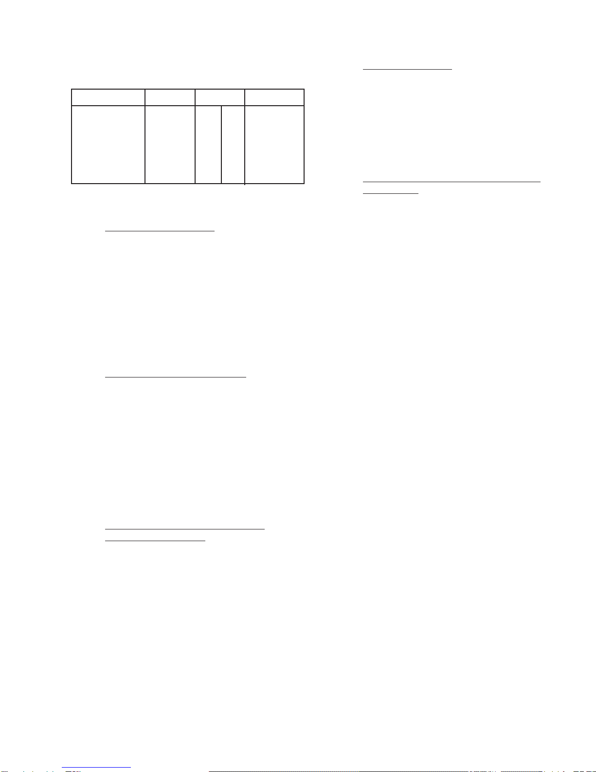
Table 2-1
RS-449/530/MIL INTERFACE PIN CONNECTIONS
25 Pin Designations EIA 530/188C 37 Pin RS449 449/MIL-188-114 Status at Connectors
AB EIA CCITT Description AB Circuit Description DCE Mode DTE Mode
1 Shield —Shield 1 Shield Shield Connected to chassis ground
7 AB 102 Signal Ground 19 SG Signal Ground Connected to chassis ground
37 SC Send Common Ground
20 RC Receive Common Ground
214
1
BA 103 Transmitted Data 4 22
1
SD Send Data Input Output
316
2
BB 104 Received Data 6 24
2
RD Receive Data Output Input
419
1
CA 105 Request to Send 7 25
1
RS Request to Send Input Output
513
2
CB 106 Clear to Send 9 27
2
CS Clear to Send Output Input
622
2
CC 107 DCE Ready 11 29
2
DM Data Mode Output Input
20 23
2
CD 108.2 DTE Ready 12 30
2
TR Terminal Ready Output Input
810
2
CF 109 Received Line 13 31
2
RR Receiver Ready Output Input
Signal Detector
24 11
1
DA 113 Transmit Signal 17 35
1
TT Terminal Timing Input Output
Element Timing (DTE)
15 12
2
DB 114 Transmit Signal 5 23
2
ST Send Timing Output Input
Element Timing (DCE)
17 9
1
DD 115 Receiver Signal 8 26
1
RT Receive Timing Output Input
18 LL 141 Local Loopback 10 LL Local Loopback Input Output
21 RL 140 Remote Loopback 14 RL Remote Loopback Input Output
25 TM 142 Test Mode 18 TM Test Mode Output Input
TELECOMMUNICATIONS TECHNIQUES CORPORATION
5
Table 2-2
Twinax Connector References
Circuit Bal Pins Unbal Pins
RCV DATA RD 6 24 6
RCV CLK RT 8 26 8
TX DATA SD 4 22 4
TX CLK OUT TT 17 35 17
EXT CLK IN ST 5 23 5
* Referenced to the RS-449, Recommendation
2.2.1 General Characteristics
The RS-449/530/MIL Data Interface, Model 41400, has
the following dimensions and weight:
Height: 1.5” (38.0 mm)
Width: 7.5” (185.0 mm)
Depth: 5.23” (133.0 mm)
Weight: 13.6 ounces (386 grams)
2.2.2 Equipment and Items Included
ThereisnoequipmentrequiredtoinstalltheRS-449/530/
MIL Data Interface, Model 41400. The RS-449/530/MIL
Data Interface, Model 41400, is simply installed into the
FIREBERD with thumb screws. Refer to paragraph 5.2 for
installation instructions. No other equipment is necessary or
provided. No other items are included with the RS-449/530/
MIL Data Interface, Model 41400, other than this Operating
Manual.
2.2.3 Tools and Equipment Required for
Periodic Maintenance
There are no tools or equipment required for periodic
maintenance. Periodic maintenance consists of cleaning the
RS-449/530/MIL Data Interface, Model 41400’s exterior
with a clean, lint free cloth. Cleaning sprays should not be
useddirectlyontheinterface. Contactsshouldrequirelittleor
no periodic maintenance. Contacts may be cleaned with a
clean lint-free cloth. Contacts should not be cleaned with an
abrasive cleaner.
2.2.4 Equipment Storage
The RS-449/530/MIL Data Interface, Model 41400,
should be stored in the original shipping container when not
in use. Both the FIREBERD and the RS-449/530/MIL Data
Interface, Model 41400, should be stored in a moisture and
vibration free environment.
2.2.5 Unpacking, Assembly, and Installation
Instructions
ThepackagecontainingtheRS-449/530/MILDataInter-
face, Model 41400, should be carefully checked for exterior
damage. If no damage is apparent, the package should be
openedcarefullyso that theRS-449/530/MILData Interface,
Model 41400, is not damaged with a cutting blade or other
sharp object. The RS-449/530/MIL Data Interface, Model
41400,shouldbecheckedagainstthebillofmaterials(BOM)
to make sure that everything matches. Check the RS-449/
530/MIL Data Interface, Model 41400, for any apparent
exterior damage. Report any damage to the carrier and to
TTC. Refer to warranty and return information in Chapter 8
of this manual.
AssemblyoftheRS-449/530/MILDataInterface,Model
41400, is not required. The unit comes completely as-
sembled. The interface itself, is the lowest replaceable unit
(LRU). Installation procedures are provided in Section(s) 3
and 5 of this manual.
2.3 FUNCTIONAL DESCRIPTION
TheRS-449/530/MILDataInterface,Model41400,gives
the FIREBERD 6000 DCE and DTE emulation capabilities.
The RS-449/530/MIL Data Interface, Model 41400, has
25-pin D-type and 37-pin D-type or twinax connectors. In
addition, the RS-449/530/MIL Data Interface, Model 41400,
is capable of operating in either a balanced or unbalanced
mode. ControloftheRS-449/530/MILDataInterface,Model
41400,isviatheFIREBERD6000frontpanelinterfacesetup
menuorby remote control.TheRS-449/530/MIL Data Inter-
face, Model 41400, is capable of receiving data and clock
inputsfromawidevarietyofdatasources. Italsohasdataand
clock outputs for testing purposes. Internal circuitry consists
ofaninternalclockgenerator,patterngenerator,andreceiver.
Thiscircuitryallowsforawidevarietyoftestingcapabilities.
A six-position DIP switch allows for the selection of the
groundtermination. Paragraph2.3.6 contains additionalDIP
switch details.

6
TELECOMMUNICATIONS TECHNIQUES CORPORATION
The RS-449/530/MIL Data Interface provides the FIRE-
BERD Communications Analyzer with the ability to test and
analyze RS-449, MIL-188-114, EIA-530, and MIL-188C
compatible circuits using either the 25-pin, 37-pin, or twinax
connectors. The following information provides a functional
description of each TYPE of interface operation. For more
information on TYPE selection, see Section 3.
2.3.1 RS-449
When TYPE RS449 is selected, the RS-449/530/MIL
Interface operates in accordance with EIA RS-449, CCITT
V.10 and V.11, and ISO 4902-1980. TYPE RS449 enables a
FIREBERD to act as data terminal equipment (DTE) or data
communicationsequipment(DCE)whenD-typeconnectoris
selected. Connections are made using a 37-pin D-type con-
nectorortwinaxconnector. Operationispossibleinbalanced
or unbalanced mode. Balanced mode indicates that each
signalistransmittedontwoleadsinwhichthevoltageisequal
in magnitude and opposite in polarity with respect to a
common reference. This mode is preferred when minimum
noise and cross talk is desired. Unbalanced mode indicates
that each signal is transmitted on one lead with respect to a
common ground. Data transmission is supported in synchro-
nous or asynchronous timing. With asynchronous timing,
asynchronous data analysis can be performed at speeds up to
20 kb/s. With synchronous timing, operation at 15 Mb/s is
possible.
2.3.2 MIL-188-114
When TYPE 188114 is selected, the RS-449/530/MIL
Interface operates in accordance with the MIL-STD-188-114
Bipolar Balanced and Unbalanced Interface Specification,
datedMarch1976. TYPE188114enablesaFIREBERDtoact
as data terminal equipment (DTE) or data communications
equipment (DCE). Connections are made using a 37-pin
D-type connector with operation possible in balanced or
unbalancedmode. Balance mode indicatesthat eachsignal is
transmitted on two leads in which the voltage is equal in
magnitude and opposite in polarity with respect to a common
reference. This mode is preferred when minimum noise and
cross talk is desired. Unbalanced mode indicates that each
signal is transmitted on one lead with respect to a common
ground. Data transmission is supported in synchronous or
asynchronous timing. With asynchronous timing, asynchro-
nous data analysis can be performed at speeds up to 20 kb/s.
With synchronous timing, operation at 15 Mb/s is possible.
2.3.3 EIA-530
When TYPE EIA530 is selected, the RS-449/530/MIL
InterfaceoperatesinaccordancewithEIA530specifications.
TYPE EIA530 enables a FIREBERD to act as data terminal
equipment(DTE)or data communications equipment(DCE).
Connections are made using a 25-pin D-type connector. Op-
erationispossibleinbalancedorunbalancedmode. Balanced
mode indicates that each signal is transmitted on two leads in
which the voltage is equal in magnitude and opposite in
polarity with respect to a common reference. This mode is
preferred when minimum noise and cross talk is desired.
Unbalanced mode indicates that each signal is transmitted on
oneleadwithrespecttoacommonground. Datatransmission
is supported in synchronous or asynchronous timing. With
asynchronous timing, asynchronous data analysis can be per-
formed at speeds up to 20 kb/s. With synchronous timing,
operation at 15 Mb/s is possible.
2.3.4 MIL-188C
When TYPE 188C is selected, the RS-449/530/MIL
Interface operates in accordance with the MIL-STD-188C
Interface specification. This interface enables the
FIREBERD to act as data terminal equipment (DTE) or data
communications equipment (DCE). Connections are made
using a 25-pin D-type connector. Operation is in unbalanced
mode. Unbalanced mode indicates that each signal is trans-
mitted on one lead with respect to a common ground. Data
transmission is supported in synchronous or asynchronous
timing. Withasynchronous timing, asynchronousdataanaly-
sis can be performed at speeds up to 20 kb/s. With synchro-
nous timing, operation at 64 kb/s is possible.
2.3.5 Twinax Connectors
The five twinax connectors RCV DATA, RCV CLK,
TXDATA,TXCLKOUT,andEXTTXCLKINenablesthe
FIREBERD to test a wide variety of data handling devices.
Theconnectorsenableoperationinbalancedandunbalanced
modewiththeconnectorshieldsconnectedtochassisground,
themiddleconductorcarryingtheCategoryII(B)signal,and
thecentercarryingtheCategoryI(A)signal. Balancedmode
indicatesthateachsignalistransmittedontwoleads(A&B)
in which the voltage is equal in magnitude and opposite in
polarity with respect to a common reference. This mode is
preferred when minimum noise and cross talk is desired.
Unbalancedmodeindicatesthateachsignalistransmittedon
one lead (A) with respect to a common ground. Data
transmission is supported in synchronous or asynchronous
timing. Withasynchronoustiming,asynchronousdataanaly-
sis can be performed at speeds up to 20 kb/s. With synchro-
noustiming,operationat15Mb/sispossible. Datagenerated
by the FIREBERD is transmitted through the TX DATA
jack. The synchronous transmitted clock signal is sent
through the TX CLK OUT jack. Data is returned to the
FIREBERD for analysis through the RCV DATA jack. The
synchronous returned clock is sent through the RCV CLK
TELECOMMUNICATIONS TECHNIQUES CORPORATION
7
jack. A clock signal via the EXT TX CLK IN jack may be
selected as the timing source for the transmitted data signal.
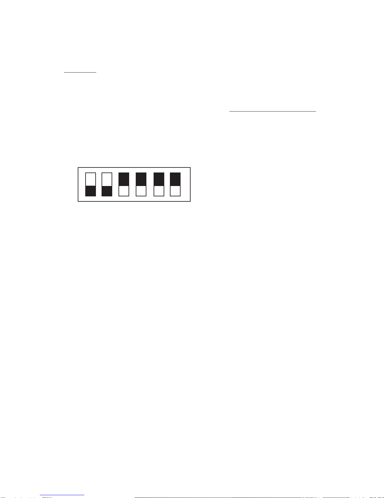
2.3.6 DIP Switch
Use DIP switch position 3, 4, and 5 to reduce the ampli-
tudenoiselevelontheEXTTXCLKIN,RCVCLK,andRCV
DATAleadsbychangingthelinetolinetermination to line to
ground termination. The 124 ohm line to line termination of
the external transmit clock input, receive clock, and receive
data may be split by placing a 62 ohm resistor from each line
to ground. Figure 2-2 illustrates the factory settings for the
DIP switches.
resistorsarenotterminatedtogroundallowinglinetoline
termination. In the opposite (CLOSED) position the
center of the resistors are terminated to ground allowing
line to ground termination.
2.4 MAINFRAME OPERATION WITH THE
RS-449/530/MIL INTERFACE
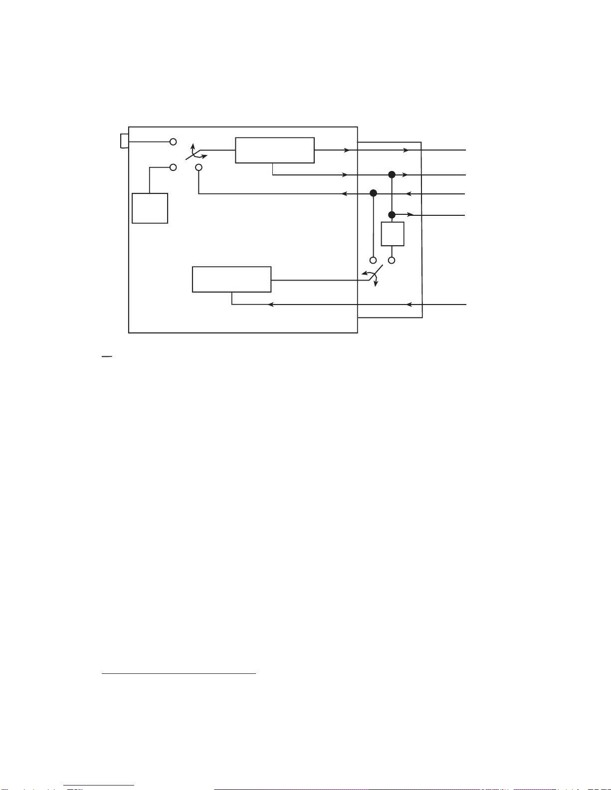
2.4.1 Emulating Synchronous DTE
The FIREBERD mainframe generator clock and pattern
selections must be configured for operation with the
RS-449/530/MILInterface. Figure2-3illustratesasimplified
block diagram of the FIREBERD emulating synchronous
DTE. The diagram shows the relationship between the gene-
rator clock, test pattern generator, receiver, and RS-449/530/
MILInterfacetransmitandreceivedataandclockleads. Two
sets of pin numbers are identified: the EIA-530/MIL-188C
connectorandtheRS-449/MIL188-114whichisinparenthe-
sis. See Table 2-1 for pin out descriptions.
NOTE: OnlyCategoryIcircuitsareidentified. SeeTable2-1
for corresponding Category II circuits.
The generator clock selection establishes which clock
source is used during testing: the internal (INTRNL), inter-
face (INTF), or external (BNC). When the generator clock is
settoINTRNL,themainframesuppliestheclocksourcefrom
the internal generator clock which is used to generate the test
pattern on Pin 2 Transmitted Data (Pin 4 Send Data) and
supply the external transmit clock on Pin 24 Transmit Clock
DTEsource(Pin17TerminalTimingDTEsource). TheDCE
transmit clock on Pin 15 Transmit Clock DCE source (Pin 5
Send Timing DCE source) is ignored when the internal
mainframe clock is used.
Withthe generatorclock set toINTF, theclock on Pin 15
(Pin 5) is used as the transmit timing source for transmitting
the test pattern on Pin 2 (Pin 4). It also supplies the external
transmitclockonPin24(Pin17). Typically,theDCEsupplies
transmit timing to the DTE on Pin 15 (Pin 5) and the DTE
(FIREBERD)generates the data(test pattern) fromthat clock
and redistributes the timing signal on Pin 24 (Pin 17) to the
DCE. Setting the generator clock for INTF is the recom-
mended selection when the FIREBERD is emulating DTE.
With the generator clock set for BNC, the mainframe is
supplied with the clock source through the GEN CLK IN
connector on the rear panel. The received data is clocked in
on Pin 3 Received Data (Pin 6 Receive Data) with the receive
clock from the DCE on Pin 17 Receive Clock (Pin 8 Receive
Timing) supplying the timing. Signal analysis is performed
on the received data and receive clock signals.
Figure 2-2
DIP Switch Factory Settings
Position 1 and Position 2 are not used.
Position3 ExternalTx Clock Input - This switch allows
the center of the two EXT TX CLK IN 62 ohm resistors
to be connected to ground. In the normal (OPEN)
position the two 62 ohm resistors are not terminated to
ground allowing line to line termination. In the opposite
(CLOSED) position the center of the resistors are termi-
nated to ground allowing line to ground termination.
Position4ReceiveClock-Thisswitchallowsthecenter
ofthe two RCVCLK 62 ohmresistors to beconnectedto
ground. In the normal (OPEN) position the two 62 ohm
resistorsarenotterminatedtogroundallowinglinetoline
termination. In the opposite (CLOSED) position the
center of the resistors are terminated to ground allowing
line to ground termination.
Position 5 Receive Data - This switch allows the center
of the two RCV DATA 62 ohm resistors to be connected
toground. Inthenormal(OPEN)positionthetwo62ohm
1 2 3 4 5 6
Open
Closed
9500385-00

8
TELECOMMUNICATIONS TECHNIQUES CORPORATION
Figure 2-3
FIREBERD Emulating Synchronous DTE
During DCE emulation, the Interface Status and Control
panel switches control RLSD (Received Line Signal Detec-
tor)andDSR(DataSetReady)byturningtheleadsoffandon.
The status of RTS (Request to Send), LL (Local Loopback),
RL (Remote Loopback), and DTR (Data Terminal Ready) is
monitoredand displayedon the front panel. TM (Test Mode)
and CTS (Clear to Send) are controlled using the Signaling
Menu.
2.4.3 Emulating Asynchronous DTE/DCE
When selecting asynchronous DTE/DCE operation the
data bits (5, 6, 7, on 8), parity (EVEN, ODD, NONE), and the
stop bits (1, 1.5, or 2) need to match the parameters of the
equipment being tested. The FIREBERD can emulate asyn-
chronous DTE/DCE and operate from 50 kb/s to 20 kb/s. Set
the generator clock to INTERNAL and select the appropriate
clockfrequencytomatchtherequireddatarate. Donotusethe
BNC selections when operating asynchronously.
Thefollowingpatternsarevalidinasynchronoustesting:
MARK, SPACE, 1:1, 63, 511, 2047, 215-1, FOX, and USER
Set the pattern selection to any test pattern, except FOX
and USER 1-3. If the Long User Option is installed these
patterns may be selected.
During DTE emulation, the Interface Status and Control
panel switches control RTS (Request To Send) and DTR
(Data Terminal Ready) by turning the leads off and on. The
status of RLSD (Received Line Signal Detector), DSR (Data
Set Ready), TM (Test Mode), and CTS (Clear To Send) is
monitored and displayed on the front panel.
2.4.2 Operating as Synchronous DCE
The FIREBERD mainframe generator clock and pattern
selections must be configured for operation with the RS-449/
530/MIL Interface. Figure 2-4 illustrates a simplified block
diagram of the FIREBERD 4000 emulating synchronous
DCE. The diagram shows the relationship between the
generator clock, test pattern generator, receiver, and RS-449/
530/MIL Interface transmit and receive data and clock leads.
Two sets of pin numbers are identified: the EIA-530/MIL-
188C connector and the RS-449/MIL 188-114 which is in
parenthesis. See Table 2-1 for pin out descriptions.
FIREBERD
Receiver
INTF
Pattern
Generator
INTF
DATA
CLK
CLK
DATA
RS-449/530/MIL
Transmit Data 2
Send Data (4)
Transmit CLK DTE Source 24
Terminal Timing (17)
Transmit CLK DCE Source 15
Send Timing (5)
Receive CLK 17
Receive Timing (8)
Receive DATA 3
Receive DATA (6)
GEN CLK IN BNC
Internal
Gen Clock
INTRNL
KEY
EIA 530/188C Reference
RS-449/MIL-188-114 Reference
9500386-00
TELECOMMUNICATIONS TECHNIQUES CORPORATION
9
Figure 2-4
FIREBERD Emulating Synchronous DCE
1-3. If any other pattern is selected, ASYNC PATTERN
CONTENTION flashes in the ANALYSIS RESULTS
display.
During DCE emulation, the Interface Status and Control
panel switches control RLSD (Received Line Signal Detec-
tor)andDSR(DataSetReady)byturningtheleadsoffandon.
RL (Remote Loopback) and LL (Local Loopback) are con-
trolledusingtheSignalingMenu. ThestatusofRTS(Request
to Send), LL (Local Loopback), RL (Remote Loopback), and
DTR (Data Terminal Ready) is monitored and displayed on
the front panel. During DTE emulation, the Interface status
and Control panel switches control RTS (Request To Send)
and DTR (Data Terminal Ready) by turning the leads off and
on. The status of RLSD (Received Line Signal Detector),
DSR (Data Set Ready), TM (Test Mode), and CTS (Clear To
Send) is monitored and displayed on the front panel.
2.4.4 Operating in the Self-Loop Mode
In DTE emulation, the self-loop mode loops the TD lead
Pin2(Pin4)totheRDleadPin3(Pin6)andthe XTC lead Pin
24 (Pin 17) to the RC lead Pin 17 (Pin 8). Timing can be
provided by the DCE on Pin 15 (Pin 5) [generator clock set to
INTF], the internal generator clock [generator clock set to
INTRNL],ortherearpanelGENCLKINconnection[genera-
tor clock set to BNC].
In DCE emulation, the self-loop mode loops the RD lead
Pin 3 (Pin 6) to the TD lead Pin 2 (Pin 4) and the RC lead Pin
17 (Pin 8) to the XTC lead Pin 24 (Pin 17). Timing can be
provided by the internal generator clock (generator clock set
to INTRNL) or the rear panel GEN CLK IN connection
(generator clock set to BNC). User connections do not have
to be disconnected to perform the self-loop test.
FIREBERD
Receiver
INTF
Pattern
Generator
TT
DATA
CLK
CLK
DATA
RS-449/530/MIL
Received DATA 3
Received DATA (6)
Receive CLK 17
Receive Timing (8)
Transmit CLK DTE Source 24
Terminal Timing (17)
Transmitted DATA 2
Send DATA (4)
GEN CLK IN BNC
Internal
Gen Clock
INTRNL
KEY
EIA 530/188C Reference
RS-449/MIL-188-114 Reference 9500387-00
TT
Delay
ST
Transmit CLK DCE Source 15
Send Timing (5)

10
TELECOMMUNICATIONS TECHNIQUES CORPORATION
TELECOMMUNICATIONS TECHNIQUES CORPORATION
11
SECTION 3
FIREBERD 4000
INSTALLATION AND OPERATION
3.1 INTRODUCTION
This section describes how to install, configure, and
operate the RS-449/530/MIL Data Interface with a FIRE-
BERD 4000. Refer to the FIREBERD 4000 User’s Guide or
the FIREBERD 4000 Reference Manual for mainframe oper-
ating procedures.
NOTE: ConfiguretheFIREBERD4000andtheRS-449/530/
MIL Data Interface before connecting the FIRE-
BERDto thecircuit undertest. This avoidsunneces-
sary circuit downtime.
3.1.1Repair and Replace Procedure
The RS-449/530/MIL Data Interface, Model 41400, is
providedasa self-containedunit. Ifrepairsarenecessary,the
entire interface should be replaced. Section 8 of this manual
contains information about the warranty and return policies.
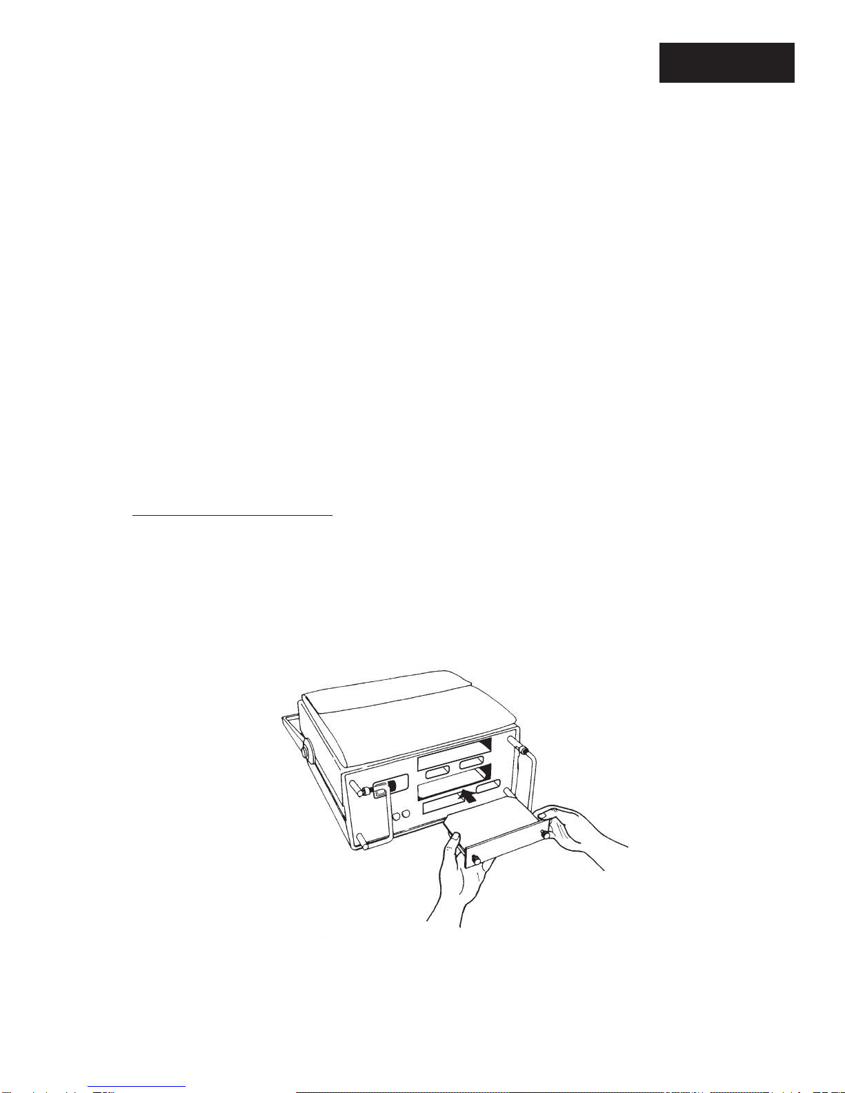
3.2 INSTALLING THE INTERFACE
The following procedure describes how to install the
RS-449/530/MIL Interface in the FIREBERD 4000. Figure
3-1 illustrates how the interface is installed.
CAUTION: Before installing or removing the interface mod-
ule, turn the AC power OFF to the FIREBERD
mainframe. Damage can occur to the interface
and mainframe.
1. Power OFF the FIREBERD.
2. Face the FIREBERD rear panel.
NOTE: TheFIREBERD4000mayhavetwointerface
slots. SLOT1 (bottom slot) is the standard
interface slot and SLOT2 (top slot) is the
optional interface slot (Option 4001).
Figure 3-1
Installing a Modular Interface
9500388-00

12
TELECOMMUNICATIONS TECHNIQUES CORPORATION
3. Insert the interface into a vacant interface slot.
Verify that the interface faces up.
4. Slide the module into the FIREBERD until the
interface panel is flush with the rear panel. Make
sure the PC board edges are fitted into the card
guides inside the interface slot.
5. Secure the interface with the two thumbscrews on
the interface panel.
3. 2. 1 Performance Verification
The proper performance of the RS-449/530/MIL
Data Interface, Model 41400, is verified by installing the
interfacein the FIREBERD4000as described inthe previous
paragraphs. The FIREBERD 4000 should be setup as de-
scribed in the step-by-step procedures in the following para-
graphs. Theequipmentshouldbepowered-upandthevarious
menus and setups performed to ensure proper operation. If
any test fails, be sure to check connections, continuity of
cables,andproperseatingoftheinterfaceintotheFIREBERD.
An analysis of test results and proper performance indicators
are provided in the analysis results section at the back of this
section. In addition, the FIREBERD 4000 Reference Manual
provides additional performance verification and validation
results.
3.2.2 Calibration Procedures
The RS-449/530/MIL Data Interface, Model 41400, is
factorycheckedandrequiresnocalibration. TheFIREBERD
4000 is calibrated as described in the FIREBERD 4000
Reference Manual.
3.2.3 Parts List and Vendors List
No parts list or vendors list is provided because the
RS-449/530/MIL Data Interface, Model 41400, is the LRU.
See Section 8 of this manual for replacement and warranty
information.
3.3 FIREBERD 4000 INTERFACE SET-UP
This section describes how to access the interface menu
and discusses each of the menu selections in the RS-449/530/
MIL Data Interface menu.
TheRS-449/530/MILDataInterfaceiscontrolledthrough
the FIREBERD 4000 INTERFACE SETUP category. Press
the MIL449 softkey to access the MIL449 interface menu.
Use the SETUP SELECT switch to step through the menus.
Press the softkeys to select a function as indicated by the
softkey labels on the bottom line of the display. To return to
the interface select menu, press the mainframe HOME key.
All interface menu settings are retained when power is re-
moved from the mainframe. See Figures 3-2 through 3-7 for
the interface menus.
3.3.1 Operating Type Menu
The Operating Type (TYPE) menu allows the user to
select either 188114, RS449, EIA530, or 188C as the type of
interfaceoperation. Presstheappropriatesoftkeytoselectthe
desired operating type. Press the MORE key to display the
188Csoftkeylabel. ModifyingTYPEwillcauseatestrestart.
188114 - The 188114 operating type configures the
interface to be connected to a MIL-188-114 compatible
circuit.
RS449 - The RS449 operating type configures the inter-
face to be connected to a RS-449 compatible circuit.
EIA530 - The EIA530 operating type configures the
interface to be connected to a EIA-530 compatible cir-
cuit.
188C - The 188C operating type configures the interface
to be connected to a MIL-188C compatible circuit.
3.3.2 Connector Menu
Theconnector(CONNECTOR)menuonlyappearswhen
TYPE 188114 or TYPE RS449 is selected. This menu
controls the type of data interface which the FIREBERD can
beconnected to. Modifying CONNECTORwill causes atest
restart. PressingtheassociatedsoftkeyselectseitherD-TYPE
or TWINAX.
D-TYPE - When the D-TYPE softkey is pressed, the
interface is configured to use the RS-449/MIL188-114,
37-pin connector.
TWINAX - When the TWINAX softkey is pressed, the
interface is configured to use the twinax connectors.
3.3.3 Emulate Menu
The Emulate (EMULATE) menu establishes the inter-
face emulation mode. Pressing the associated softkey selects
either DTE or DCE emulation. This menu does not appear
when the selected CONNECTOR is TWINAX.

TELECOMMUNICATIONS TECHNIQUES CORPORATION
13
Figure 3-2
FIREBERD 4000 RS-449/530/MIL Data Interface Setup Menu
Type RS-449 D-Type
Figure 3-2
FIREBERD 4000 RS-449/530/MIL Data Interface Setup Menu
Type RS-449 D-Type
9500389-00
★
EMULATE DCE
★★
EMULATE DTE
INTERFACE: XXXXXX
INT232 MIL449 INT188
INTERFACE: MIL449
INT232 MIL449 INT188
TYPE: XXXXXX
188114 RS449 EIA530
MORE
TYPE: RS449
188114 RS449 EIA530
188C
CONNECTOR: XXXXX
D-TYPE TWINAX
CONNECTOR: D-TYPE
D-TYPE TWINAX EMULATE: XXXXXX
DTE DCE MODE: XXXXXX
BAL UNBAL
MODE: UNBAL
BAL UNBAL
MODE: BAL
BAL UNBAL
IMPEDANCE: XXXXXX
78 100 124
UNTERM MORE
TIMING: XXXXXX
ASYNC SYNC
TIMING: SYNC
ASYNC SYNC
RCV CLOCK: XXXXXX
TT ST
★
TIMING: ASYNC
ASYNC SYNC DATA BITS: XXXXXX
5 6 7
8
PARITY: XXXXXX
EVEN ODD NONE STOP BITS: XXXXXX
1 1.5 2
★
★★
TM:XXX CTS:XXX
TM CTS
LL:XXX RL:XXX
LL RL
SIGNALING: ON=XXX
POS NEG

14
TELECOMMUNICATIONS TECHNIQUES CORPORATION
Figure 3-3
FIREBERD 4000 RS-449/530/MIL Data Interface
Setup Menu
Type RS-449 Twinax
Figure 3-4
FIREBERD 4000 RS-449/530/MIL Data Interface
Setup Menu
Type 188/114 D-Type
Figure 3-5
FIREBERD 4000 RS-449/530/MIL Data Interface
Setup Menu
Type 188/114 Twinax
Figure 3-6
FIREBERD 4000 RS-449/530/MIL Data Interface
Setup Menu
Type 188C
Figure 3-7
FIREBERD 4000 RS-449/530/MIL Data Interface
Setup Menu
Type EIA530
9500390-00
★
EMULATE DCE
INTERFACE: XXXXXX
INT232 MIL449 INT188
INTERFACE: MIL449
INT232 MIL449 INT188 TYPE: XXXXXX
188114 RS449 EIA530
188C
MORE
TYPE: RS449
188114 RS449 EIA530
188C
CONNECTOR: XXXXXX
D-TYPE TWINAX
CONNECTOR: TWINAX
D-TYPE TWINAX MODE: XXXXXX
BAL UNBAL
MODE: UNBAL
BAL UNBAL
MODE: BAL
BAL UNBAL
IMPEDANCE: XXXXXX
78 100 124
UNTERM MORE
TIMING: XXXXXX
ASYNC SYNC
TIMING: SYNC
ASYNC SYNC
RCV CLOCK: XXXXXX
TT ST
★
TIMING: ASYNC
ASYNC SYNC DATA BITS: XXXXXX
5 6 7
8
PARITY: XXXXXX
EVEN ODD NONE STOP BITS: XXXXXX
1 1.5 2
Figure 3-3
FIREBERD 4000 RS-449/530/MIL Data Interface Setup Menu
Type RS-449 Twinax
Table of contents


