TTC FIREBERD 6000 User manual

-~
ARTISAN
®
~I
TECHNOLOGY
GROUP
Your definitive source
for
quality
pre-owned
equipment.
Artisan Technology
Group
Full-service,
independent
repair
center
with
experienced
engineers
and
technicians
on staff.
We
buy
your
excess,
underutilized,
and
idle
equipment
along
with
credit
for
buybacks
and
trade-ins
.
Custom
engineering
so
your
equipment
works
exactly as
you
specify.
•
Critical
and
expedited
services
•
Leasing
/
Rentals/
Demos
• In
stock/
Ready-to-ship
•
!TAR-certified
secure
asset
solutions
Expert
team
ITrust
guarantee
I
100%
satisfaction
All
tr
ademarks,
br
a
nd
names, a
nd
br
a
nd
s a
pp
earing here
in
are
th
e property of
th
e
ir
r
es
pecti
ve
ow
ner
s.
Find the VIAVI Solutions / JDSU / TTC 40202 at our website: Click HERE

Quick
Cards
TbeseQuick
Cuds
bave
been
asembkd
to
be&
usem
emilyperfm
basic
testfunctim.
Tbe
Quick
Cuds
are
ah
emue
toolr
to
fanuiarize
new
users
wltb tbe
PIREBERD
6000
test
set.
TouretbeQuickCmdc
I.
Select
tbedesitpdqt@aatim
fmn,
the Tableof Contents.
2.
Refi
totbe
appyWiate
setup
card
to cmp@re the
FUU?BERD
60W.
3.
Ifadditiond inzm
is
needed,
refer to the
PLRpBBRD
MXM
User's
Guide
I
Table
of Contents
Codpation
Wups
Full
TI In-SerivceMonitoring
Tlm1Out-of-SeniceBERT
Tlm1-Voice
and
Signaling
ANSI T1.403
PRMs
with the
41440A
Interface
2M In-Service Monitoring
2WNx64 Out-of-Senice
BERT
Wf-Service V.35 Testing
DSOA
Out-of-SeniceTesting
Out-of-Senice RS232 Testing
Frame &lay Out-of-Service
Frame Relay In-Service
Frame Relay
IP
Ping
AppppUCati0~
Frame Relay In-Senice Monitoring
Frame Relay
local
Conndvity
Test
(link
Management Verification)
Frame Relay End-to-End
Conneclivity
Tesl
FaneRelay
IP
Ping Test
Full.TI
T1.lTI.BERT
Tl.IT1.Voice
ANSI.Tl
2M.h-Senice
2M.Out-Senice
V.35
DSOA
I8232
Fr.Relay.0~1-Service
Fr.Re4ay.h-Service
Fr.Relay.Ping
TTC
Technical
Support
1-800-638-2049
FB6000-TOCXard1.1/3.97
Artisan Technology Group - Quality Instrumentation ... Guaranteed | (888) 88-SOURCE | www.artisantg.com
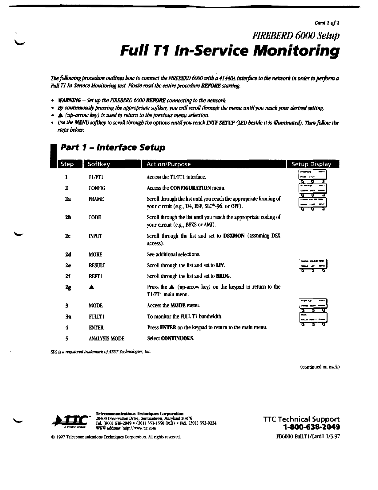
Full
TI
In-Service
oni it or in^
~be~ngprocadwe
outlines
bow
townnecttbe
PLRBB~RD
60W
wii%
b
414&
intm$ke
to
tbe
netuwk
in
wdR.tops&m
a
Pull
TI
In-ServlceMonitm'ng
test.
&w&reud
tbe
enrireprocedum
BEFORRstarting.
.
WB-SetuptkP~60W~connectingtotbe~.
.
@
conti@mng
tbe
appopiak
soflby,
you
dscmU
tbrougbtbe menu untilyou
)8a~byarr
desirsdsSmng.
A
(up-amnu
by)
is
dtoreturn to tbepeviousmenu sektlon.
.
use
ise
tliesophey
to
snoll
tbrough
tk
optionsunrilyou reach
~~
(LBD
beside
it
is
illuminated).
Thfdbw
tte
steps
bebw:
I
PaH
1
-
lntedace
Setup
Tlrn1
CONFIG
WAm
CODE
m
MORE
RESULT
m1
A
MODE
FULLT1
ENTER
ANALYSIS
MODE
Access the Tl/ETIinterface.
Access the
CONFIGURATION
menu.
Scrollthrough the
list
untilyou
reach
the appropriateframingof
your circuit (e.g.,
D4,
ESP,
SLP-%,
or
OFF).
Scrollthrough the
List
until you
reach
the appropriatecodingof
your circuit (e.g.,
B8ZS
or
AM).
Scroll through the list
and
set
to
DSXMON
(assuming
DSX
access).
See
additionalselections.
Scrollthrough the
list
and
set
to
LIY.
Scrollthrough the
lisl
and
set
to
BRDG.
Press the
A
(up-mw
key)
on the
keypad
to
return
to
the
TIml
main
menu.
Access
the
MODE
menu.
To monitor the
FULL
T1
bandwidth.
Press
ENlER
on the
keypad
to
rehun
to
the main menu.
Select
comous.
(contmued
rm
back)
TTC
Technical
Support
1-800-638-2049
pg6000Full.TI/Cudl.l/3.97
Artisan Technology Group - Quality Instrumentation ... Guaranteed | (888) 88-SOURCE | www.artisantg.com

Part
2
-
Performing the Test
,
1
Press
RESTART
to
clear
alarms
and
begin
the test. Venfy
that:
A.
mREBERD
6000's
PAITERN
SYNC
LF.D
is illuminated
(indicating
a
signal
is
present).
B.
F'IREBERD 6000's
PRM
SYNC
LED
isilluminated
(if
PRM
SYNC
is
not illuminated,go
back
to
Step
2a
and
select
the appropriateframeformat).
Table
I
lists
intportantMYLSIS
RBSm
tbal
sboull
be
cbecw.
I
Table
7
-
Analysis Results
T-CARRIBR
BWs
FRA
ERR
CRC
ERR
FRA
LOSS
BIT
SLIP
SIGNAL
+LVL
dB
-LVL
dB
PP
LVL
v
RCV
FREQ
Bipolar Violalions
Frame Emors
CRC
Ermn
(ESF
framing
only)
Frame
Loss
Bit Slips (applicableonly
with
a REFCl)
Positive Receive Signal
level
Negative Receive Signal
Level
Peak-to-PeakReceive Signal
level
(volts)
Receive Frequenrj
I
Table
2
-
Interface Status LEDs
CODE
ALM
1
ALM
2
Illuminates
when
B8ZS
cading
is
being
received.
Illuminates
when
a
Yellow
Alarm
isdetected.
Illuminates
when
an
Excess
Zeros
Alarm
is
detected.
0
1997
Teleeommunicltions
Technique
Corpontion.
All
rights
mewed.
lTC
Technical
Support
d
1-800-638-2049
FB6000Full.Tl/Cardl.lI3.97
Artisan Technology Group - Quality Instrumentation ... Guaranteed | (888) 88-SOURCE | www.artisantg.com

TIIFTI
Out-of-Sewice
BERT
WAWYZm;
-
Set
up
tbe
PIRh'BBRD
MXM
BBPORP
connecting
to
tk
nehuork.
By
amtinuouslypresstngtk
appropriate
sofikey, you
dsd
thgb
tk
menu untilyou mbyour
&redsetting.
A
(up-anwu
key)
is
used
to
return to tkpmfusmuselection.
Use tkMENUsofikey to
sd
thgbtkoptwnsuntilyou reacb~~
(LED
&side
it
is
illuminated).
Tbm
folbur
tk
StGpS
belau:
I
Part
1
-
Interface Setup
1
TIAT1 Access the TIAT1 interface.
2
CONFIG
Access the
CONFIGURATION
menu.
2a
FRMlE
ScmU thmughthe list
unUl
you
reach
theappropriateftamingof
your circuit (e.g.,
D4,
ESF,
SIP-%,
or
OR).
2b
CODE
ScmU thmughthe list untilyou
reach
the appropriatecodingof
your circuit (e.g.,
B8ZS
or
MI).
2c
INPUT
Scroll through the list
and
set
to
'TERM
2d
MORE
See additionalselectiom
2e
RESULT ScmU through the list
and
set
to
SII)
2f
LBO
ScmU through the list
and
set
the
Line
Build
Out
to
0
dB.
%
FmT1 Scrollthrough the list
and
set
to
BRDG.
2h
A
Press
the
A
(up-mw
key)
on the
keypad
to
return
to
the
previous menu.
3
ERRINS
Set
to
OW.
3a
A
Press the
A
(up-mw
key)
on the
keypad
to
return
to the
previous menu.
4
MODE
Access the
MODE
menu.
4a
PULLTI Allows you
to
select
and
BWT
the
PULL
T1
bandwidth.
SLC
is
a
@lered
tdmmk
ofAT6T
TecbMbgies,
1m
(continued
on
back)
TTC
Technical
Support
1-800-638-2049
Artisan Technology Group - Quality Instrumentation ... Guaranteed | (888) 88-SOURCE | www.artisantg.com

I
Part
1
-
Interface Setup
(cont.)
d
m-m
..
..
A
.B
..
ma1
MORE
CLRAU.
56/64
MORE
CH#
W
CH#
DN
lWRT
A
MORE
LOOP
WE
A
RESPND
A
RCVBn'
CH#
W
CH#
DN
A
IDLE
ENTER
ENTER
Select and monitor any selection of lime slots. Tn5con unse-
lected channels
will
be replaced with the idle code entered in
Step
7.
(Repeat
Steps
4b5
and
4b6
for each channel you
wish to 1st.)
See
additionalselections
Clear
all
channelsetupparameten from a previous test.
Choose between
56K
and
64K
bandwidth.
See
additionalselections.
Select the channelsyou wish to drop
Set the selectedchannel to
1WRX.
press
the
A
(up-mwkey) on the keypad
twk%
to return to
the TIAT1main menu.
See
additionalselections
Access the
LOOP
menu.
Select which piece of equipmentyou want
to
loop back. Press
MORE
foradditionalselections
if
needed.
Press
the
A
(up-mow key) on the keypad to return to the
LOOP
menu.
Set the
HREBERD
6000
to
AUTO
(automalically respondsto a
received loop code) or
NONE.
Pressthe
A
(up-mwkey) on the keypad
&ice
to return to
the TILT1
main
menu.
Selecta channel
1-24
to be displayedin the
RCV
BITE
result.
Selectthe channel you wish to monitor.
Press the
A
(up-mow
key)
on the keypad
to
return to the
TliFC1 main menu.
Select an 8-bit binary idle code panern
to
be
inserted in the
inactivechannels.
Press
to set these idle code bits.
Press
on the keypad to returnto the main menu
(continuedon
Card
2)
TTC
Technical
Support
d
1-800-638-2049
FB6000-TI.fll.BERT/Card1.2/3.97
Artisan Technology Group - Quality Instrumentation ... Guaranteed | (888) 88-SOURCE | www.artisantg.com
TIIFTI
Out-of-Service
BERT
(-t)
I
Part
1
-
Interface Setup
(cont.)
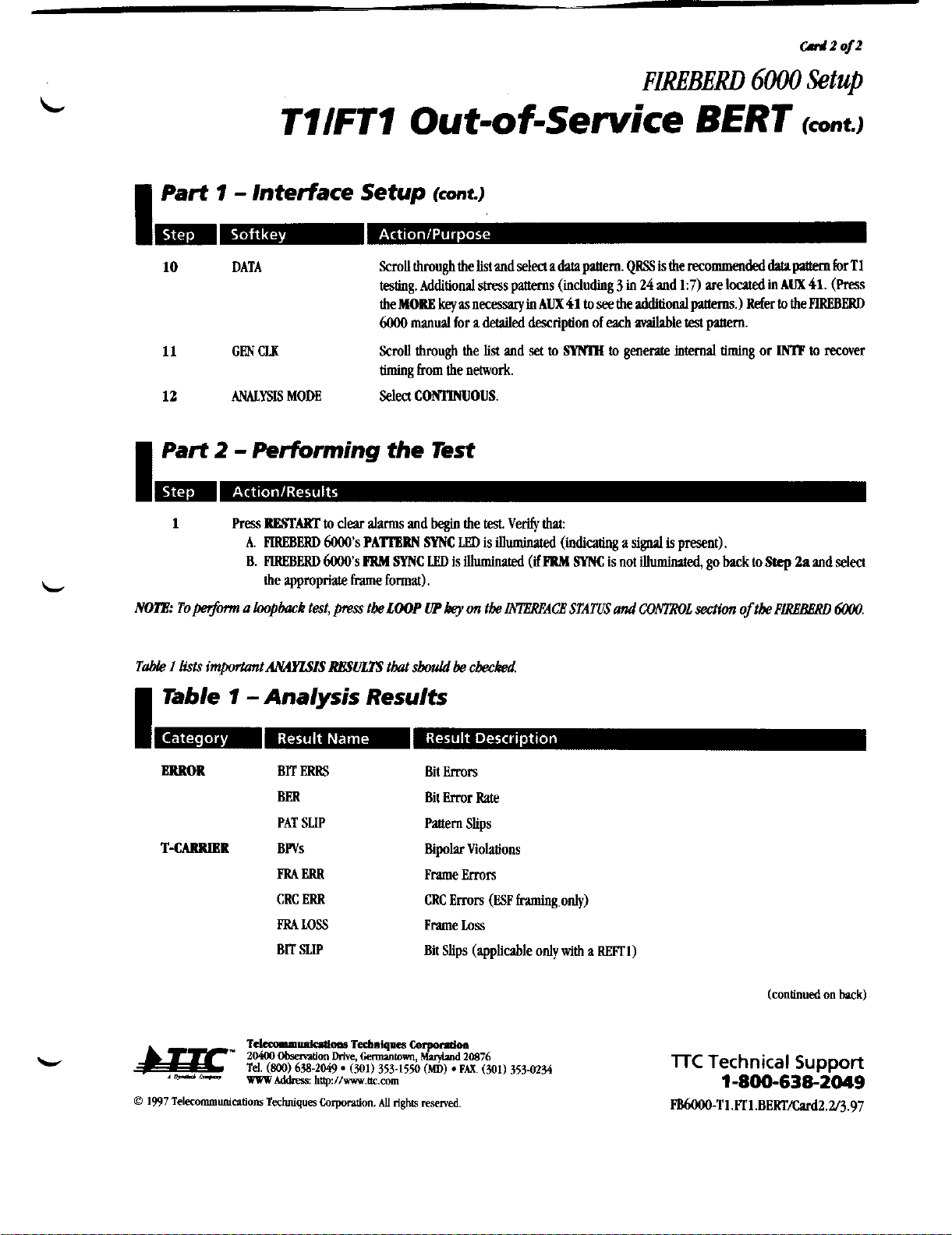
10
DATA
Scrollthrough thelistand
select
a
data
pattern.
QRS
is
the
recommended
data
pvtem
for
Tl
testing.
Additionalstresspanems
(including
3
in
24
and
1:7)
are
located
in
AUX
41.
(Press
the
key
as
necessiy
in
AUX
41
to
s&
the
additid
paaerns.)
Refer
to
the
FlREBERD
6000
manual
for
a
detailed descriptionof
each
4le
test
panem.
11
GEN
CLK
Scroll
though
the list and
set
to
SWIM
to
generate
internal
timing
or
IMP
to
recover
timing
from the network.
12
ANALYSIS
MODE
Select
CONIlNUOUS.
I
Part
2
-
Performing the Test
1
Press
BBSFART
to
dear
llvms
and
begin
the
test.
Verify
that:
A.
FlREBERD
6000's
PATIERN
SYNC
la,
is
illumhated
(indicating
a
signal
is present).
B.
PlREBERD
6000's
FRM
SYNC
IJ!D
is
illuminated
(if
FRM
SYNC
is
not
illuminated,go
back
to
Step
2n
and
select
the appropriateframe format).
MlE:
To+
a
loopback
test,
@press
tbe
LOOP
UP
key
on
tbe
INlBREACE STATIIS
und
CONTROL
section
of
tbe
PLRBBBRD
6000.
Table
I
lists
importuntAU4YLSIS
RBSULTS
that
sW
be
chM.
I
Teble
7
-Analysis Results
ERROR
BIT
ERRS
BER
PAT
SLIP
T-CAIIRIBR
BWs
FRA
ERR
CRC
ERR
FRAm
BIT
SUP
Bit
Errors
Bit Error Rate
Pattern
Slips
BipolarViolations
Frame Errors
CRC
Errors
(ESP
fnmingonly)
Frame
bss
Bit Slips (applicableonly
with
a
Wl)
lTC
Technical
Support
1-800-638-2049
PB6000-Tl.ml.BERT/Card2.2/3.97
Artisan Technology Group - Quality Instrumentation ... Guaranteed | (888) 88-SOURCE | www.artisantg.com
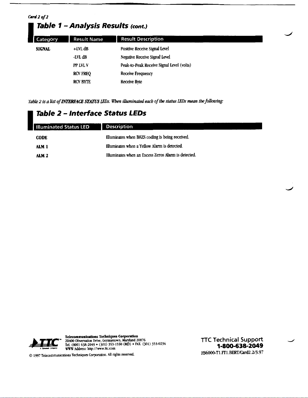
Table
1
-
Analysis Results
(co"~.)
SIGNAL
+LVL
dB
Positive ReceiveSigoalLevel
-LVl.
dB
Nqative
ReceiveSignalLevel
PP
Ln
V
Peak-to-PeakReceiveSignal Level (volts)
RCV
FREQ
ReceiveFrequency
RCV
BlTE
Receive
Bvte
Table2
is
a
list
of
INTEREACE
STATUS,WDs.
Vh
iiUumi~ted
eacb
of
the
status
LEDs
mean
the
fdlowing:
Table
2
-
Interface Status LEDs
CODE
ALM
1
ALM
2
Illuminates
when
B8ZS
coding
is
beingreceived.
Illuminates
when
a
Yellow
Alarm
is
detected.
illuminates
when
an
Excess
Zeros
Alarm
is
deteaed.
TelsommunldoM
Technlqow
Co~ntion
"
20400
Obmtion
Drive,
Germantown,
Mvylvld
20876
Tel.
(800)
638-2049. (301) 353-1550
(MD)
.PAX
(301) 353-0234
lTC
Technical
Support
d
1-800-638-2049
F86000-Tl.kTl.BERF/cud2.2/3.97
Artisan Technology Group - Quality Instrumentation ... Guaranteed | (888) 88-SOURCE | www.artisantg.com

FIREBEIRD
GOO0
Setup
TllFTl-
Voice
and
Signaling
TkfdbwingptDcadum
wtliw
bow
toconnecttbe
PLRBBeRD
6WO
with
a
4144lM
i&rjface
to
tbe
netumr.4
in
oriier
toperfanr
an
d-to-end
Tlml
Out-of-Seruice Voice andSigdingtest.
Please
read
tk
entimpmcedumBBPI)RBstarting,
.
W~-SetuptbeP~6WO~mnecringtotknetumr.4.
4
conNnuou.dy~'ng
tk
appropriate
sopkey,
p
you2
moll
tbrougb
tk
menu untilp
raacb
yarr
&siradsetting.
A
(up-
hey)
is
used
to
return
to
tkprevious
menu
sektion.
Use
tk
dlBMIsvphey
to
moll
tbmugh theoptions
untilyou
reach
INIF
SETOP
(LED
beside
it
is
illumiMted).
Tben
f&
tbe
stspsbelau:
I
Part
1
-
Interface
Setup
Tlml
corn
FRMlE
CODE
m
MORE
RESULT
LBO
m1
A
ERRINS
A
MODE
MORE
VOICE
SEL<
Access
the Tlm1interface.
w
Access
the
CONFIGURATION
menu.
ScmU through the list
until
you
reach
the appropriate
framingof
your circuit (e.g.,
D4,
ESF,
SLP-96,
or
Om).
Scmllthrough thelist
until
you
reach
the appropriate
dmg
of
your circuit
(e.g.,
BSZS
or
AM).
Scroll through the list
and
set
to
TERM.
See
additional selections.
Scrollthrough the
list
and
set
to
SID.
Scrollthrough the list
and
set
the Line
Build
Out
to
0
dB.
Scroll through the list
and
set
to
m.
Press
the
A
(up-mow
key)
on the
keypad
to
rrturn
to
the
Tlm1
main
m&u.
Set
to
om.
Press
the
A
(up-amnv
key)
on the
keypad
to
rehrrn
to
the
_I3
TlmImain menu.
I
ml
Access
the
MODE
menu.
--I
See
additional
selections.
Places
the
PlREBERD
6000
into
VOICB
mode
Pm
to choose
between
setting
your
IX
channel
or your
RX
w&iJ
channel (toggle
between
RX=<TX-<,
and TX-<RX=<.)
(continued
on
back)
@
1997TelffommuniononsTffhniqua
Corpanfion.
M
rights
reserved
TTC
Technical
Support
1-800-638-2049
FB6000-Tl.FTl.Voice/Cud1.1/3.97
Artisan Technology Group - Quality Instrumentation ... Guaranteed | (888) 88-SOURCE | www.artisantg.com

w1
of1
I
Part
I
-
Interface Setup
(ant.)
d
m-m
.
.
.-
-
..
r.
4bZ
CHXUP
Selectyour
TX
and
RX
channels.
CHX
DN
4b3
MORE
See
additionalvoice selections.
4c
SIC
Set
to
ON.
(Use
the front panel
keypad
to
set
the
ABCD
signaling
bits forESFframingor
AB
bits for
D4
framing
in
binary format.)
4cl
ENTF.R
Press
to enter the values selected.
5
ENTER
Press
BNlBR
on the
keypad
to
retum
to
the
main
menu.
6
GEN
CLK
Scroll through the
lin
and set to
SYNM
to generaIe internal
timing or
IMF
to recover timing
from
the network
7
ANALYSIS
MODE
Select
CONmWOUS
I
Part
2
-
PerForming the Test
/~the~tintotk~-8~t.iackk
wbkbislocatedon
the
TILT1
I~aceModule
(cloicefrannnLFsiaJqtim
cun
now
k
mjied
on
an individualch@.
1
Press
RESTART
to
dear
alarmsand
begin
the
test.
Verify
that:
A.
FlREBERD
6000's
PATIERN
SYNC
LED
is
illuminated (indicating
a
sgnal
is
present).
B.
HREL3ERD
6000's
PRM
SYNC
LED
is
illuminated
(if
PRM
SYNC
isnot
illuminated,
go back
to
Step
2n
and select
the appropriateframe format).
J
TaMe
1
lists
inrporrantAN4YLFIS
RBSULTS
tbatsbould
be
checked
I
Table
1
-
Analysis Results
T-CARRIBR
RXABCD
Receive
ALW
bits
Table
2
is
a
list
of
IiWEREACB
STATUS
LBDs.
117bm
iUuminated
each
of
tk
status
Dsmntkfollauing:
I
Table
2
-
Interface Status LEDs
CODE
Illuminateswhen
B8ZS
ccding
is
being
received.
ALM
1
Illuminates
when
a
Yellow
Alarm
is
detected
ALM
2
illuminates
when
an
ExcessZeros
Alarm
is
detected
MTR:
Using
tbis
mode,
pw
may
cbeck
tkintegrity
of
tkcircuit
by
insertingandmonitoringmice tm&, andmonita'ngand
tmmittingsignalingbits
on
individudchannelswitbintk
TImTI
bits-. Usingtbis
modegiwa
quickcbeck
oftk
intsgrty
of
tkcircuit
and
mjiespmper
signaling
seguences.
For
example,
you
may
set
tksigndingbitsfor
on-kwh
and
tben
verii
tbat
pmpr
off-book
bitsare being returned
Tebxommoniufions
Tshnlqun
Cnprrulon
"
204W
Obsemtion
Drive,
Gmultom.
Mqluld
20876
Tel.
(800)
638-2049.
(30,) 353-1550
(MD)
PAX.
(301) 353-0234
TTC
Technical
Support
J
*
+-
-
VW
Address:
http://muc.eom
1-800-638-2049
0
1997
Telffommuniarions
Teehniqes
CorponUon.
NI
tighs
reserved.
EB6000-T1.FTl.Voice~Cud1.1/3.97
Artisan Technology Group - Quality Instrumentation ... Guaranteed | (888) 88-SOURCE | www.artisantg.com
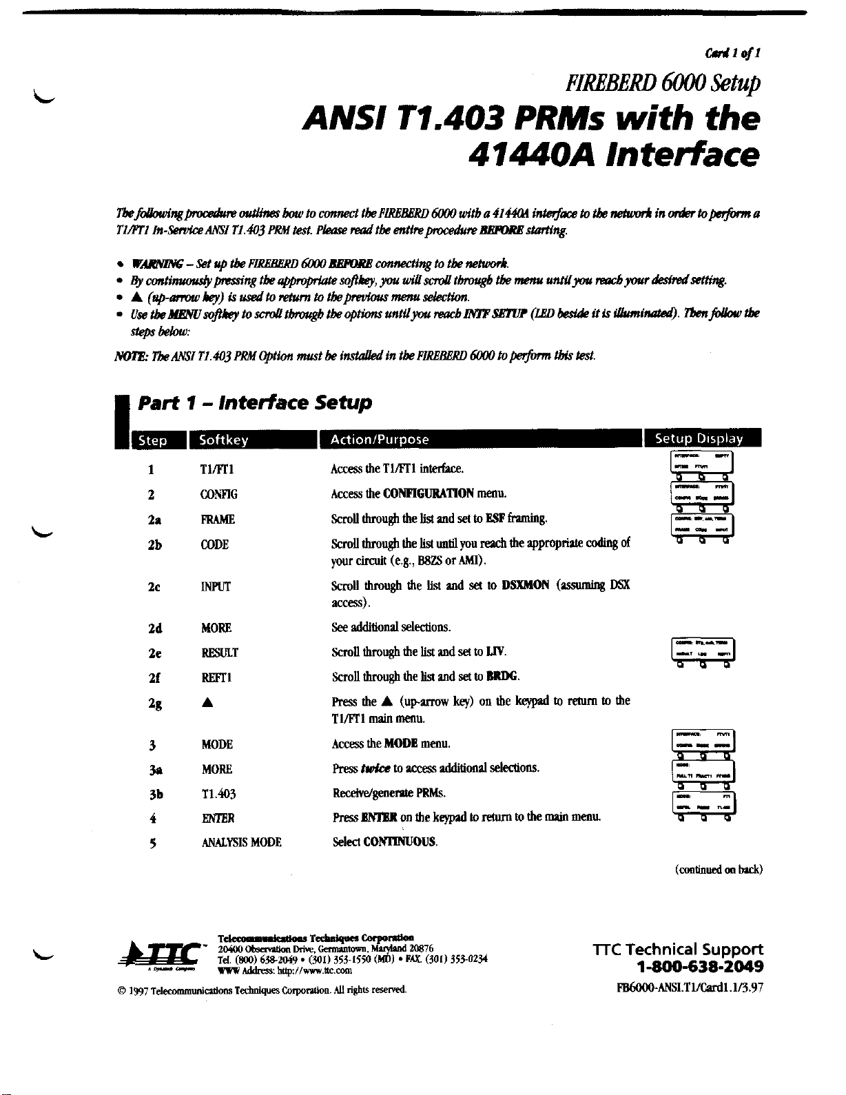
crrJ1
o/l
FIMBERD
6000
Setup
ANSI T7.403
PRMs
with the
4M4OA Interface
Wm
-
Set
up
tbe
F~6000
BERME
connectingto tk
nehmrk.
By
oatinuoudypmnpmnngtbe
applprtate
soPhey,
you willsciwl tbreugb tk
menu
untUpu
dyour
&misetting.
A
(up-
hey)
is
dto
return
to
tkpmdow
menu
selection.
use
tbeblEWsofikey
to
sciwlthgbtk
options
untuyou
reacblMPSE?W
(ZED
!&&
it
is
iUumiMtad).
Tbmjbbw
tbe
steps
below:
MllE:
Tbe
MSI
Tl.43
PRM
Option must be
insrclued
h
tk
PtREBBRD 6000
toperfonntbis&st.
I
Part
1
-
Interface
Setup
Tlrnl
CONFIG
PaAME
CODE
INPUT
MORE
RESULT
m1
A
MODE
MORE
T1.403
rn
ANALYSIS
MODE
Access
the
TIN1
interface.
Access
the
CONFIGURATION
menu.
ScmU through the
list
and
set
to
ESP
framing.
Scrollthrough the
list
until
you
reach
the appropriate
coding
of
your
circuit
(e.g.,
BSZS
or
AMI).
ScmU through the
list
and
set
to
DSXMON
(wuming
DSX
access).
See
additionalselections.
ScmU through the
list
and
set
to
LIV.
Scrollthrough the
list
and
set
to
IMDG.
ResstheA
(uparmwkey)
onthekepiitorehlmtothe
Tlml
main menu.
Access
the
MODE
menu.
Press
mke
to
access
additionalselections.
Receive/genernte
PRMs.
Press~MBllwtbekqlpdtorehlmtothemPinmenu
Select
COmoUs.
(continued
m
luck)
lTC
Technical
Support
1-800-638-2049
w6ooO-ANSI.TllCudl.ll3.97
Artisan Technology Group - Quality Instrumentation ... Guaranteed | (888) 88-SOURCE | www.artisantg.com
W
Part
2
-
Pehrmingthe Test
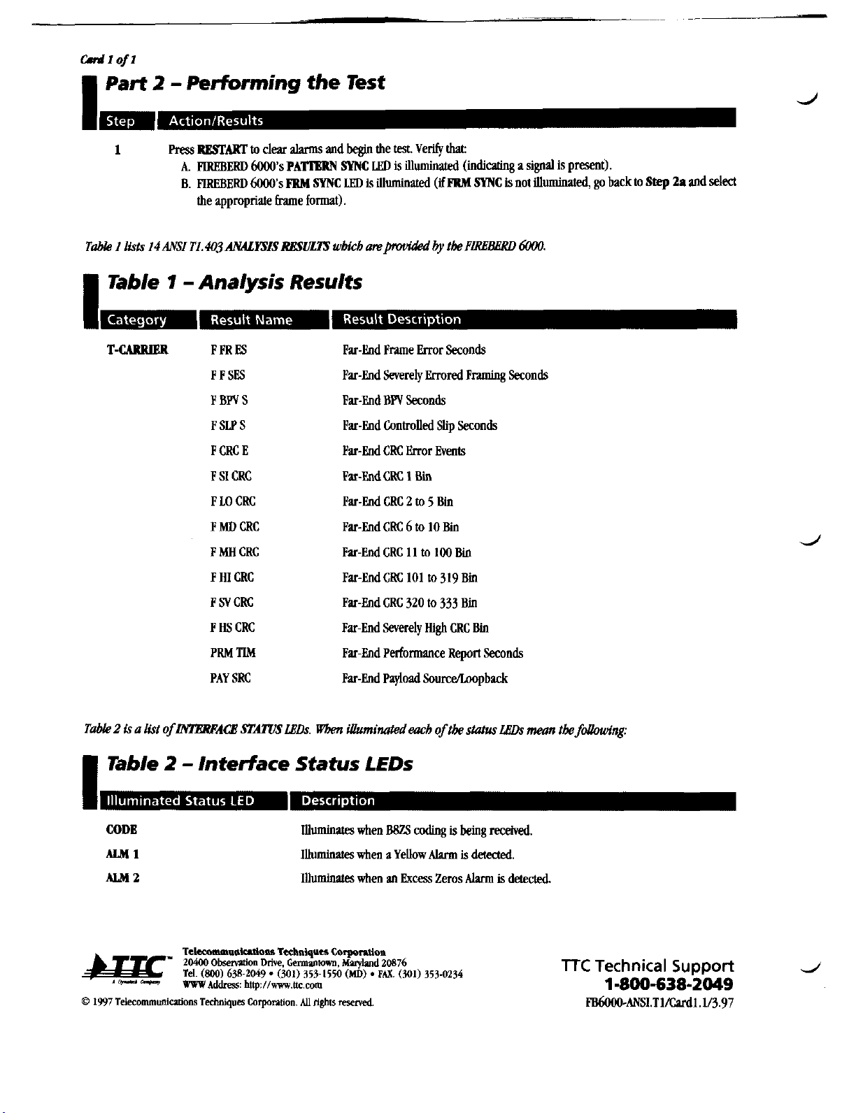
1
Press
RBSIAXT
to
dear
alvms
and
begin
the
test.
Verify
that
A.
FlREBERD
6000's
PATlgRN
SYNC
LED
is
illuminated
(indicating
a
signal
is
present).
B.
RREBERD
6000's
FRM
SYNC
LETl
is
illuminaled
(if
PBM
SYNC
is
not
illuminated,
go back
to
Step
Za
and
decl
the
appropriate
frame formal).
I
Table
1
-Analysis Results
T-CARRIER
FPRES
PPSFS
FBPVS
F
SLP
S
P
CRC
E
FSI
GRC
F
U)
CRC
FMDCRC
F
MH
CRC
F
HI
CRC
FSVCRC
FHSCRC
PRM
TIM
PAY
SRC
Par-End
Fme
Error
Seconds
Far-End
Severely
Errored
Framing Seconds
Far-End
BW
Seconds
Par-End
Controlled
Slip
Seconds
Far-End
CRC
Error
Events
Fat-EndCRC
1
Bin
Far-End
CRC
2
to
5
Bin
&-End
CRC
6
to
10Bin
Par-EndCRC
11
to
100Bin
Far-End
CRC
101
to
319
Bii
Far-End
CRC
320
to
333
Bin
Far-End
Severely
High
CRC
Bin
Far-End
Performance
Report
Seconds
Far-End
F'ayioad
Sourcehwpback
Table
2
is
a
list
ofNIBWACB
STAl'USLBDs.
Wkn
Wbenminatedtnch
of
tk
status
LhDs
mean
tk
foUowing:
I
Table
2
-
Interface Status LEDs
Illuminates
when
BBZS
coding
is
being
received.
Illuminates
when
a
Yellow
Alarm
is
detected.
Illuminates
when
an
Excess
Zms
Alvm
is
detected.
TTC
Technical
Support
d
1-800-638-2049
Artisan Technology Group - Quality Instrumentation ... Guaranteed | (888) 88-SOURCE | www.artisantg.com
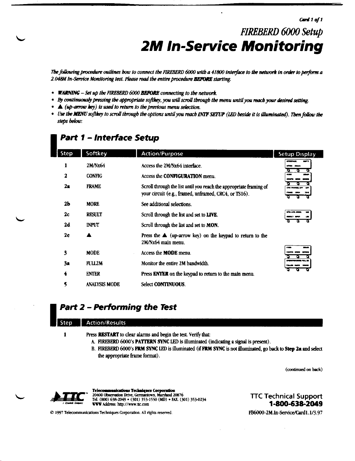
FIREBERD
6000
Setup
2M
In-Service Monitoring
I
Part
1
-
Interface Setup
1
2MINx64
Access
the
2mx64
interhce.
"
P
2
CONHG
Acw
the CONFIGURATIONmenu.
---
2a
PRAME
Scroll
throughthe
list
until
you
reach
the
appropriate
fnming
of
your
circuit
(e.g.,bed,
unframed,
CRC4,
or
TS16).
2b
MORE
2c
RmULT
2d
INFWr
2e
A
3
MODE
3a
lmL2M
4
m
5
ANALYSIS
MODE
See
additiond selections.
ScmU
throughthe
list
and
set
to
LIVE.
Scroll
throughthe
list
and
set
to
MON.
Press
the
A
(upurow
key)
on
the
keypad
to
return
to
the
2MINx64
main
menu.
Access
the MODE menu.
Monitor
the entire
ZM
bandwidth.
Press
BNIHll
on
the
keypad
to
return
to
the
main
menu.
Select
COmOUS.
I
Part
2
-
PerFonning the Test
1
Press
BESWRT
to
deu
alvms
and
b&
the
test.
Verify
that:
A.
PIREBERD
6000's
PATlBRN
~Yhk
LED
is
illuminated
(indicating
a
@
is
p-1).
B.
PIREBERI)
6000's
INRI SYNC
LED
is
illmimed
(ifINRI
SYNC
is
not
illuminated,
go
back
to
Step
2.
and
select
the
appropriate
he
format).
TTC
Technical
Support
180063&2049
m-2M.In-Senice/Cudl.1/3.97
Artisan Technology Group - Quality Instrumentation ... Guaranteed | (888) 88-SOURCE | www.artisantg.com

I
Table
1
-
Analysis Results
d
TGARlllBR
PAS
ERR
MFASERR
REBE
ERR
BIT
SUP
CODE
ERR
+LvI
dB
-LvI
dB
Rcv
FREQ
SIGNAL
PAS
Errors
WAS
Errors
(if
~~16
is
me)
REBE
Errors
Bit
Slips
(used
with
RRTl)
Code
Errors
(per
EllT
0.161)
Positive
Receive
Si
level
Negative Receive Signal level
Receive
Frequency
lTC
Technical
Support
d
1-800-638-2049
PB6000-2M.h-S&ce/Cardl.1/3.97
Artisan Technology Group - Quality Instrumentation ... Guaranteed | (888) 88-SOURCE | www.artisantg.com

crrJ1afz
FIMBERD
6000
Setup
2MINx64
Out-of-Service
BERT
I
Part
1
-
Interface
Setup
2mK64
CONFIG
PRMiE
MORE
RESULT
rn
I50
A
MODE
mM
A
ERRINS
A
MORE
mrr
TSXW
TSX
DN
Access the
2MINx64
interface.
Access the
CONFIGURATION
menu.
ScmU
through the
listuntll
you
reach
the appropriatefnming
of
your circuit (e.g.,
framed,
unframed,
CRC4,
or
lS16).
See
additionalselections.
Scroll
throughthe list
and
set
to
SlD.
ScmU
through the
list
and
set
to
IlWA.
ScmU
through the
list
and
set
theLine
Build
Out
to
0
dB.
Press
the
A
(uparrow
key)
on
the
keypad
to
return
to
the
2MINx64
main
menu.
Access the
MODE
menu.
Test
the entire
2M
bandwidth.
Press
the
A
(up-mw
key)
on the
kqlnd
to
retum
to the
2MNx64
main
menu.
Access the
BRROR
MSBRllON
menu.
Press
MB
md
hm
each
error
type
OW.
Press
the
A
(up-mw
key)
on the
keypad
to
return
to the
2Wx64
main
menu.
See
additionalselections.
Select
the timedot
0-31
to
be
displayed
in
the
RX
BlTE
resuh
(allows you
to
see
the
bytes
on
a
specifictimeslot).
Select the timeslot you
wish
to
monitor.
(continued
on
back)
TTC
Technical
Support
1-800-638-2049
Artisan Technology Group - Quality Instrumentation ... Guaranteed | (888) 88-SOURCE | www.artisantg.com

Wlof2
I
Part
7
-
Interface Setup
(cont.)
a
m-m
..
I.
-
-
.B
0.
A
AL4RMS
MORE
A
MORE
FRWORD
WAS
A
WAS
ENTER
DATA
GEN
CLK
ANALYSIS
MODE
Press the
A
(up-mow key) on the keypad
to
return to the
2M/Nx64
main menu.
Access the
ALARMS
menu.
Turn
each
type
of em
OFF.
See
additionalselections.
Press the
A
(up-mow key) on the keypad
to
return
to
the
2Wx64
main menu.
See additionalselections.
Access the
FRAMING
BIT
menu.
Edit
the binary digitsusing the keypad.
Press
ENTER
to
set
the
digits (seethe note below).
Press
the
A
(up-mow key) on the keypad
to
return
to
the
Frame Word menu.
Edit the binary digits using the keypad. Press
BNlgR
to set the
digits
(see
the note below).
Press
ENlUt
on the keypad to return to the main menu.
ScroU through the
list
and select a
data
panem.
2"-1
is
the
recommended
data
pattern. Additional
stress
patterns are lo-
catedon the frontpanel or in
AUX
41.
(Press
the
MOM
key
as
uecessaty
in
AUX
41
to
see
the additionalpatterns.)
ScmU through the list and set to
SWlX
to generate
internal
timing or
IWF
to
recovertiming fromthe network
Select
CONTINUOUS.
NO~:Mult~
alignment
si&aUow
meiw'ngequipmentto
a&
the
appmpriateABCD
signaling
bits
witb
tbeir
mspond-
ing voice
channels.
Setting the
NPAS
andMFAS
bit
will
enabk
you
to
determine whetberthe mtsignaling
bits
are
being sent
tbrougbout the netwk.
I
Part
2
-
Performing the Test
1
Press
ReSFART
to
clear
alarms
and
begin
the test. Verifythat:
A.
HREBERD
6000's
PATl%RN
SYNC
LED
is illuminated (indicatinga signal is present).
B.
FlREBERD
6000's
PRM
SYNC
Ln,
isilluminated
(if
FRM
SYNC
isnot illuminated,go back to
Step
2a
and select
the appropriateframeformat).
(continued on
Cud
2)
lTC
Technical
Support
J
1-800-638-2049
FB6000-2M.Out-S&cdCard1.2/3.97
Artisan Technology Group - Quality Instrumentation ... Guaranteed | (888) 88-SOURCE | www.artisantg.com
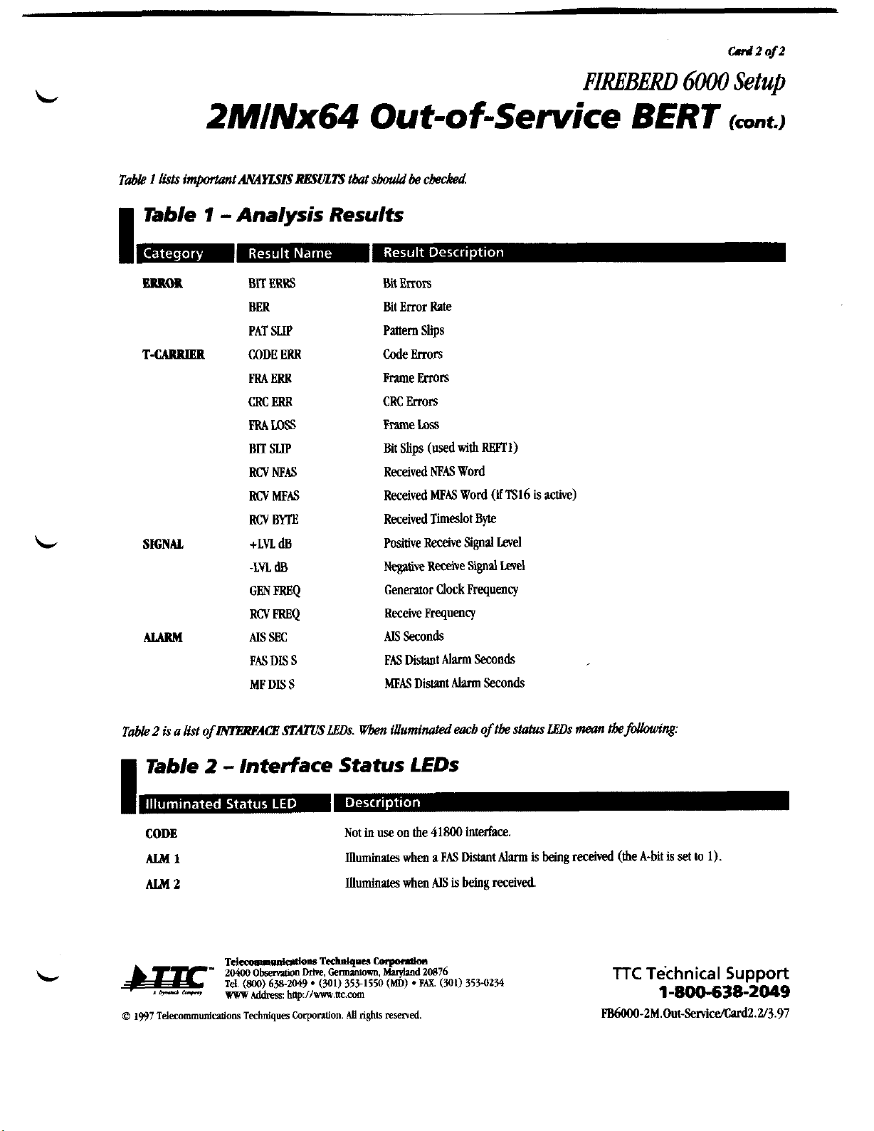
-
2MINx64
Out-of-Sewice
BERT
Tab&
I
lists
intportmrtMYLFISRESULTS
tkt
sbouki
&
cbecM
I
Table
7
-Analysis Results
BUM
BIT ERRS
BER
PAT
SLIP
T-CARRIER
CODE
ERR
PRA
ERR
CRC
ERR
PRAUlSS
BIT
SUP
RCVNEAS
RCV
MEAS
RCVm
L
SIGNAL
+LVL
dB
-LvL
dB
GFN
ERGQ
Rcv
mEQ
ALARM
.US
SEC
FAS
DIS
S
MF
DIS
S
Bit Errors
Bit Emr
Me
Panern
Slips
Code
Errors
Frame
Errors
CRC
mrs
Frame
Loss
Bit
Slips
(used
with
RE3Tl)
Received
MAS Word
Received
MFAS
Word
(ifTS16
is
active)
Received
TimeslotByte
Positive Receive
Signal
Level
Negative
Receive
Signd
level
Generator
Clock
Frequency
ReceiveFrequency
AIS
Seconds
FAS
Distant
Alm
Seconds
MEAS
Distant
Alarm
Seconds
T&
2
is
a
list
of
IMgRPAQI
STATIiS
LEDs.
Wben
illuminated
each
of
tbe
stahrs
LhDs
rnan
tbefhhdng:
I
Table
2
-
Interface Status LEDs
CODE
ALM1
ALM2
Not in use on
the 41800
interface.
Illuminates
when
a
PAS
Distant
Alarm
is
being
received
(the
A-bit
is
set
to
11,
Illuminates
when
AIS
is
being
received.
TTC
Technical
Support
1-800-638-2049
PB6000-2M.Out-SetVic~.2/3.97
Artisan Technology Group - Quality Instrumentation ... Guaranteed | (888) 88-SOURCE | www.artisantg.com
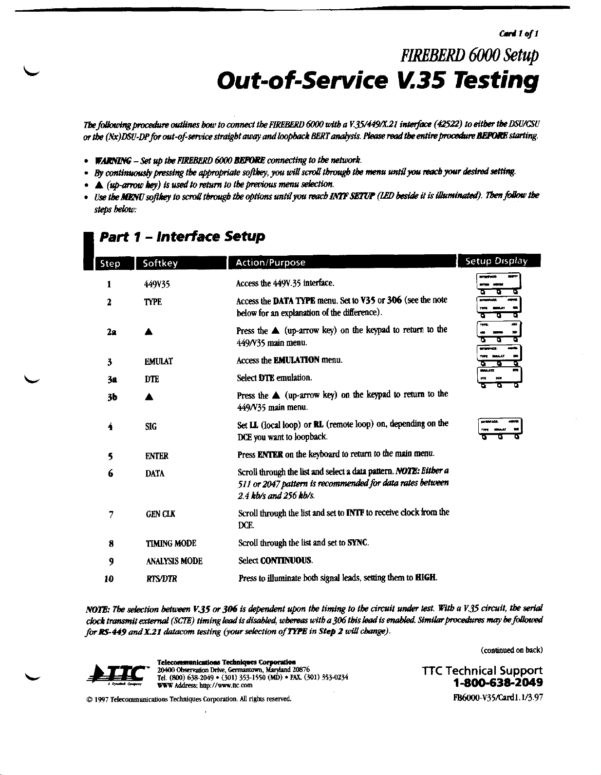
FIREBE..
6000
Setup
Out-of-Service
Y.35
Testing
I
Part
1
-
Interface
Setup
1
449V35
Access
the
449V.35
interhce.
2
TYPE Access
the
DATA
TYPB
menu.
Set
to
V35
or
306
((see
the
note
below
for
an
explvwion
of
the
ditIerence).
2P
A
Press
the
A
(upmw
key)
on
the
keypad
to
return
to
the
449N35
main
menu.
3
EMULAT
Access
the
EMULATION
menu.
3a
DTE
Selea
MB
emuhtion.
3b
A
m
the
A
(upanow
key)
on
the
kqpd
to
return
to
the
449N35
main
menu.
Set
Ih
(local
loop)
or
RL
(remote
loop)
on,
depeoding
on
the
DCE
you
wvlt
to
loopback
5
MTER
Press
ENlER
on
the
keybud
to
return
to
the
maio
menu,
6
DATA
Scroll
through
the
list
and
seled
a
data
patlera.
htHB:
Bitber
a
511
or
2047pattem
is
tmmnrendadfor
data
mtes
khueen
2.4kWs and256kWs.
7
GEN
CU(
~voUthroughthelistands~to~toree~clwkhthe
m.
8
TIMING
MODE
ScmU
through
the
list
and
set
to
SYNC.
9
ANALYSIS
MODE
Select
CONIWUOUS.
10
lrlMn'R
press
to
illuminate
both
signal
leads,
seaing
them
to
HIGH
NOTE:
Tk
&tion
betmtw
V.35
or
306
is
dejbdmt
upon
tk
timing
to
tbe circuit
under
W.
Witb
a
Y.35
circuit,
tk
serid
chk
tmmit
ertsntd
(SCE)
timing
leadis
diulMsd,
wh
wltb
a306
tbh
lead
is
enabled
Simibrpocsdures
may
kfouougd
fOIRS449andX.21
dntacan
&sting
(your&tion
ofTtPE
in
Step
2
ruillc&nge).
TTC
Technical
Support
l-8OO-638-2O49
Artisan Technology Group - Quality Instrumentation ... Guaranteed | (888) 88-SOURCE | www.artisantg.com

Cad1
of1
I
Part
2
-
Performing the Test
mm
J
1
Press
RIWART
to
dear
alarms and
begin
the
test.
Verify
that:
A. FIREBERD
6000's
PATI'ERN
SYNC
LED
is
illuminated
(indicating
a
signalis
present).
I
Table
1
-
Analysis Results
ERROR
BIT
ERRS
Change
in
Logical Value of
Bit
BER
Ratio
of Number of Errored
Bits
to
Receive
Bits
PAT
SLIP
An
Addition or Deletion
of
Bits
PBRPOEMANCE
GERR-SEC Emred
Seconds
TlME
EA
SEC Emred
Analysis
Seconds
SIGNAL
Rev
PREQ
Receive Frequencj
GEN
FREQ
Generate Frequency
ALARM
PAT
UlSS
Count
of
Pattern
Losses
C-D
CH.4
Cloc!dDafa
Phase
Changes
DAT LOSS Count of
Data
losses
CLK
UlSS
Count
of
Clock
losses
NOTE:
Ifyou
me
receivinga
hrge
numberofenors,your received clock
may
be
fe.
Ifthereceived clock ismissing
w
unusable
(a
hrge
numberof
C-D
ChX
cbrmges is
&
an
indication),the
FIRBLEW
6W
RdClock option (option
6W4)
enuhks
tbe
Dmto extracta clock
from
the
receiueddata.
Tbiswillenuhkyou to
determine
whether tbetransmisfionline
w
theclock is
tbe source of
errors.
See
thesetup belorujbr
using
theRdClockOption:
I.
Set
~~G
MODE
to
RBCOVD
(tbis
enables
tbe
PIREBERD
bWO
to
wcom
timingfmm transitionsintheincoming
data).
2.
Rw
tbeMENUso~?kqandsdthgbthelistandset to
SYMlWFRh'Q.
NOTE:
TheRenwered Clock
Option
only operates
up
to
rates of520kbh.
lTC
Technical
Support
d
1-800-638-2049
FB6000-V35/Cud1,1/3.97
Artisan Technology Group - Quality Instrumentation ... Guaranteed | (888) 88-SOURCE | www.artisantg.com
c#r
1
ojz
FIREBERD
6000
Setup
DSOA
Out-o f-sewice
Testing
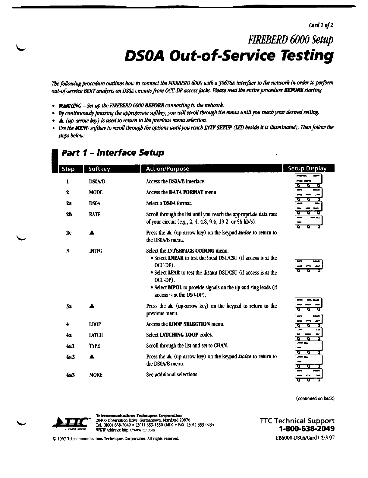
Tbe
fdbwingpocedun
outlines
tmu
to connect tk
PLRBBGRD
6WO
witb
a
306784
intet$ace
to
tbe
whmr.4
in
&
toperfonn
out-ofservice
aBRT
aaEysis
on
aFOA
circuits
from
OCU-DP
accessjacks.
Fkw
Plaaw
tbe
entinpocedum
BEFME
stariing.
WARNZIW;
-
Set
up
tbe
PLRBBBRD
6W0
dlBPORB
connectingtotknehuwk.
~y
mtinuoudypmdng
tk
ajpvpriate
sopkey,you
dsd
thgb
tk
menu untilyou
reacb
your
&mi
Wing.
A
(up-amnu
key)
is
usedto
nhun
to tbepmfous menu
selecNa.
.
Use
tk
HEWsopkeyto
sd
tbrargb
tk
optionsuntilyou
raacb
LWP
SETUP
(LBD
beside
it
is
iUuminatm9.
Tbenfollow
tbe
steps
bebw:
I
Part
1
-
Interface
Setup
DSONB
MODE
DSOA
RATE
A
m
A
rnP
LATCH
lYPE
A
MORE
Access
the
DSOA/B
interface.
Access
the
DATA
POIMAT
menu.
Select
a
DSOA
format
Scrollthrough the
list
until
you
reach
the appropriale
data
me
of your circuit (e.g.,
2,4,4.8,9.6,19.2,
or
56
Ws).
Press
the
A
(up-arrow
key)
on the
keypad
twh
to
rehm
to
the
DSONB
menu.
Selectthe
lMgllPACB
CODING
menu:
Select
LNEAR
to
test
the
local
DSU/CSU
(if
acm
is
at
the
OCU-DP).
Select
LPAR
!a
test
the
distaot
DSU/CSU
(if
access
is
at
the
OCU-DP).
Select
BWOL
to
provide
signals
on the tip
and
ring
leads
(if
access
is
at the
DSO-DP).
Press
the
A
(up-mw
key)
on the
kqpad
to
return
to
the
previous menu.
Access
the
LOOP
SBLBCTlON
menu.
Select
MTCHING
LOOP
codes
ScroU through the
list
and
set
to
WAN.
Press
the
A
(up-arrow
key)
on the
keypad
twh
to
return
to
the
DSOA/B
menu.
See
additionalselections.
TTC
Technical
Suppoa
1-800-638-2049
FB6OOO-DSOA/Cud1.2~3.97
Artisan Technology Group - Quality Instrumentation ... Guaranteed | (888) 88-SOURCE | www.artisantg.com
This manual suits for next models
1
Table of contents


