ABB TS3 User manual

888.902.6111 |www.intellirentco.com
TS3 1SDH000670R0002 L3852 EN
TS3 Trip Unit Test Set
instructions manual

888.902.6111 |www.intellirentco.com
TS3 1SDH000670R0002 L3852 2/44
Index
1. Identification .................................................................................................................. 4
2. Safety notice.................................................................................................................. 4
2.1 Notes for dielectric stiffness tests............................................................................. 4
2.2 Refe
rence standards............................................................................................... 4
3Abbreviations................................................................................................................. 5
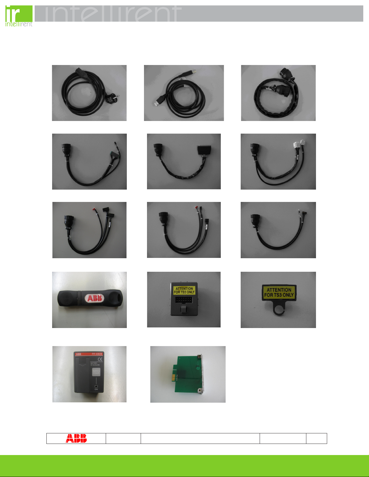
4Standard equipment....................................................................................................... 6
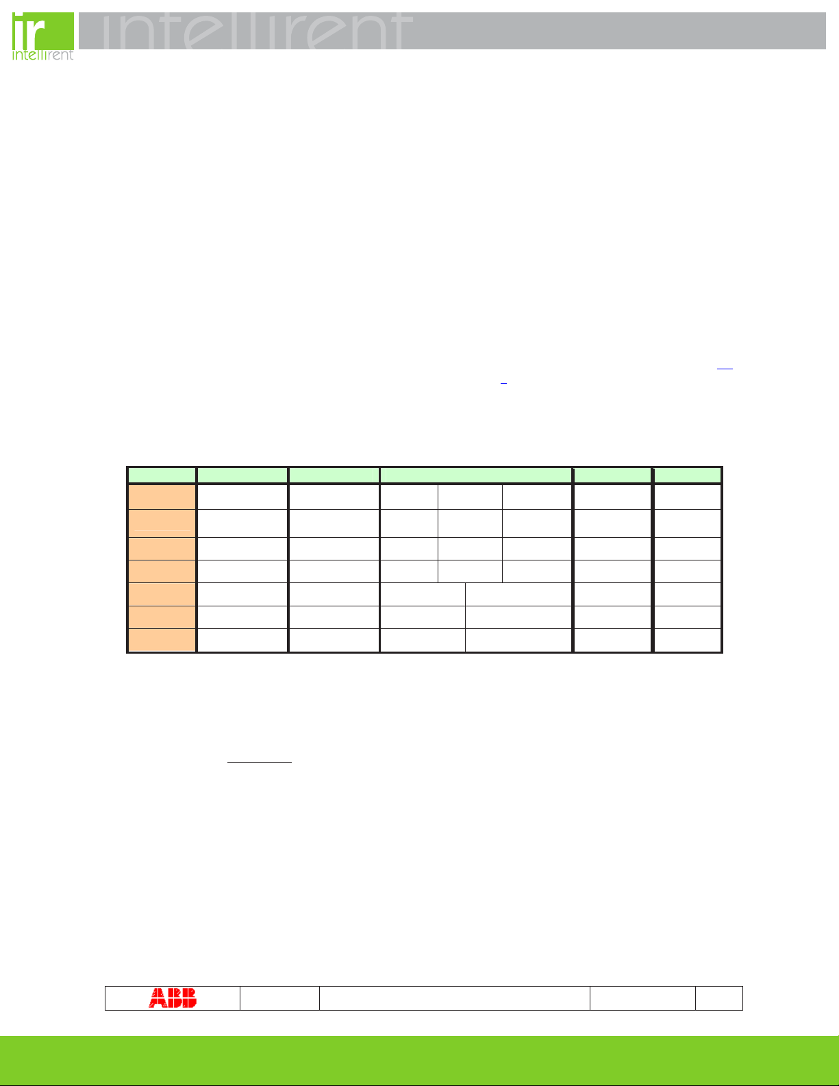
5Technical Specification................................................................................................... 6
5.1 General................................................................................................................... 6
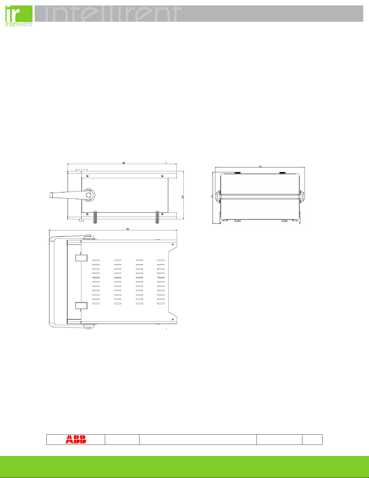
5.2 Mechanical characteristics....................................................................................... 6
5.2.1 Transport case................................................................................................. 6
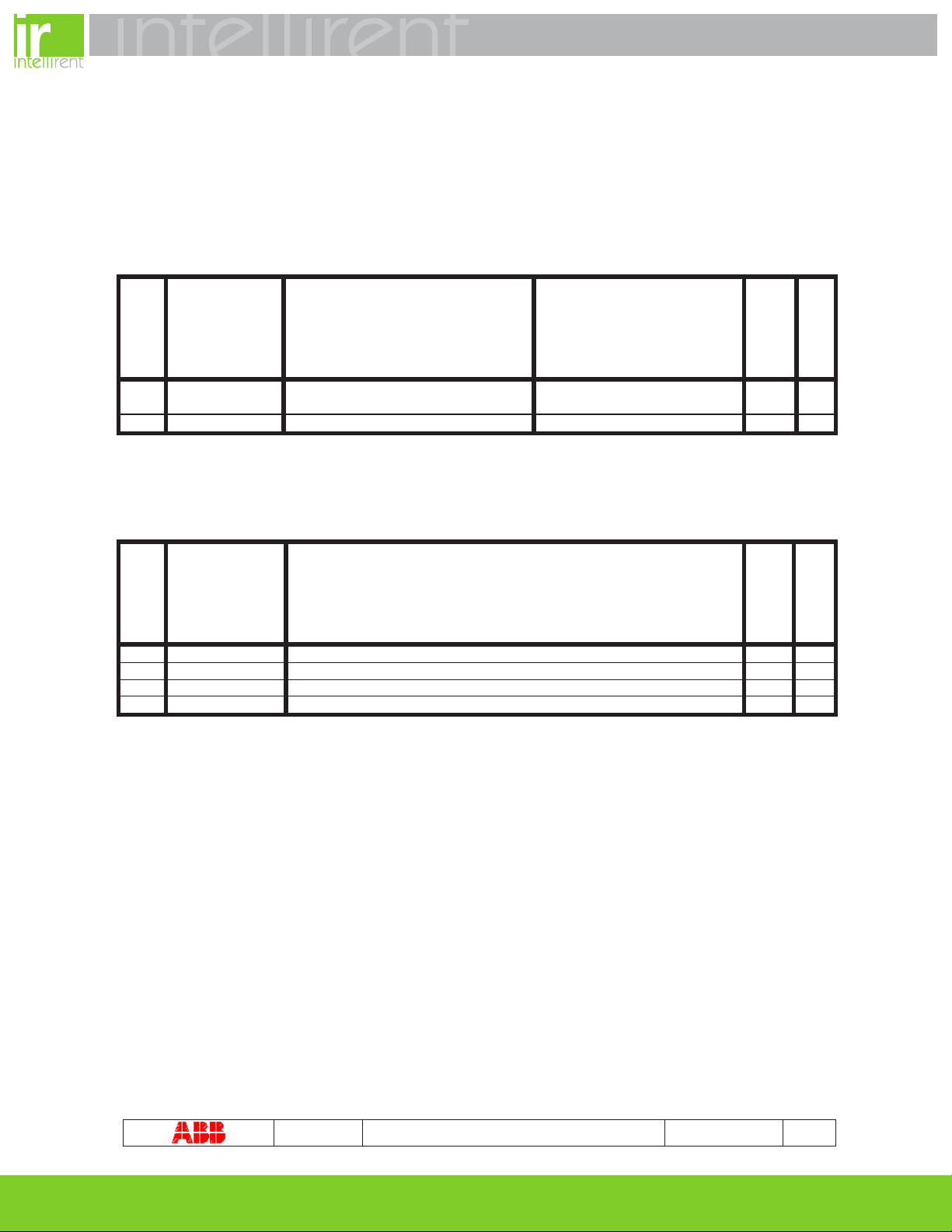
5.3 Electrical Characteristics ......................................................................................... 6
5.4 Environmental Characteristics ................................................................................. 6
5.5 Input/Output............................................................................................................ 6
5.5.1 Test connector ................................................................................................. 6
5.5.2 Alarms ............................................................................................................. 6
5.5.3 Timer ............................................................................................................... 6
5.6 Operatin
g parameters ............................................................................................. 6
5.6.1 Parameters ...................................................................................................... 6
5.6.2 TS3 Setting...................................................................................................... 6
5.6.3 User Data - Test Report ................................................................................... 6
5.7 User interface ......................................................................................................... 6
5.7.1 knob and keys use ........................................................................................... 6
5.7.2 Default Settings................................................................................................ 6
6Putting into service......................................................................................................... 6
6.1 Procedure to Set the nominal power voltage............................................................ 6
6.2 Connections............................................................................................................ 6
6.3 Menu tree ............................................................................................................... 6
6.4 Display ................................................................................................................... 6
6.5 Initial settings.......................................................................................................... 6
7Operative instructions – step by step .............................................................................. 6
7.1 Setup...................................................................................................................... 6
7.1.1 Setup Password............................................................................................... 6
7.1.2 Setup Report.................................................................................................... 6
7.1.3 Preferences ..................................................................................................... 6
7.1.4 Frequency........................................................................................................ 6
7.1.5 System date and time....................................................................................... 6
7.2 Trip unit selection.................................................................................................... 6
7.3 CB Type, Iu and In selection.................................................................................... 6
7.4 Test setup............................................................................................................... 6
7.5 Carrying out the T
EST............................................................................................. 6
7.6 Test Report............................................................................................................. 6
7.7 Info Menu ............................................................................................................... 6
8Test on protective functions............................................................................................ 6
8.1 S1 trip unit functional test. ....................................................................................... 6
8.2 S2 trip unit functional test ........................................................................................ 6
8.3 AR1 trip unit functional test...................................................................................... 6
8.4 PR1 trip unit functional test...................................................................................... 6
8.5 PR111 trip unit functional test.................................................................................. 6
8.6 PR112-PR113 trip unit functional test ...................................................................... 6
8.7 PR121-PR122-PR123 trip unit functional test........................................................... 6
8.7.1 PR121 installation ............................................................................................ 6

888.902.6111 |www.intellirentco.com
TS3 1SDH000670R0002 L3852 3/44
8.7.2 PR122- PR123 installation................................................................................ 6
8.8 PR331-PR332-PR333 trip unit functional test........................................................... 6
8.8.1 PR331 installation ............................................................................................ 6
8.8.2 PR332- PR333 installation................................................................................ 6
8.9 PR231-PR232 trip unit functional test ...................................................................... 6
9TS3 Manager Installation ............................................................................................... 6
10 Upgrade Firmware...................................................................................................... 6
11 Troubleshooting table ................................................................................................. 6
11.1 In case of a fault...................................................................................................... 6

888.902.6111 |www.intellirentco.com
TS3 1SDH000670R0002 L3852 4/44
1. Identification
TS3 is a testing device that realizes functionality verification on Low Voltage ABB SACE air circuit breakers electronic trip
units, with one-phase secondary current injection.
2. Safety notice
Read this manual carefully and completely.
The use of this device should be reserved for qualified and expert personnel only.
If in doubt, about its safe usage, the unit must be put out of service to prevent any accidental use.
You must assume that safe usage is impossible if:
1. the unit shows visible signs of damage.
2. the unit does not function (for example the display does not switch on).
3. the unit has been damaged in transit.
2.1 Notes for dielectric stiffness tests
2.2 Reference standards
TS3 test unit is CE marked and is conform to the main international reference standards in terms of electromagnetic
compatibility (EMC) and safety.
Immunity for industrial environments : IEC 61000-6-2 Standard.
Emission for industrial environments : IEC 61000-6-4 Standard.
Safety requirement for measurements, control and laboratory use electrical equipment: IEC 61010 Standard.
WARNING:
Prior to operate and / or carry out any replacements on the CB, this must be open, with
discharged spring and disconnected
Further, all connected power supplies must be disabled.
!
WARNING: this symbol gives information about operations, actions or circumstances that can cause injuries to
the personnel, damage to the unit or economic losses.
!
WARNING: before proceed with any testing and control operation with the TS3 testing device, carefully read
instructions and procedures in the following chapters.
ABB S.p.A. SACE Division disclaim all responsibility for damages to things or people, due to incorrect use of
TS3 test unit or/and for negligence on the present instructions
!
Dielectric stiffness tests on TS3, inputs and outputs, are not permitted.
In case dielectric test of any devices or circuit
breakers connected to TS3, it is necessary to remove any
connections between the TS3 and the device under test.
!

888.902.6111 |www.intellirentco.com
TS3 1SDH000670R0002 L3852 5/44
3Abbreviations
Abbreviations Meaning
AR1 MEGAMAX series trip unit
CB Circuit Breaker (for example Emax)
CBTYPE Circuit breaker version and type
CS Current sensor
DUT Device under test (i.e. trip unit)
Emax ABB SACE Air Circuit breaker series
FW Firmware
F.S. Full Scale
HW Hardware
In Trip unit nominal current
Iu Circuit breaker nominal current
Itest Test Current
MEGAMAX ABB SACE Air Circuit breaker series
NOVOMAX ABB SACE Air Circuit breaker series
PR030/B PR12x, PR23x, PR33x battery unit
PR1 MEGAMAX series trip unit
PR11x EMAX series trip units
PR120/B PR112, PR113 battery units
PR12x New EMAX series trip units
PR23x Tmax T7 series trip units
PR33x New EMAX X1 and Tmax T7 series trip units
Trip unit Electronic protection release
S1 NOVOMAX series trip unit
S2 NOVOMAX series trip unit
SW Software
TC Trip Coil
Tmax ABB SACE Molded Case Circuit Breaker series
TS3 Trip unit test set
TS3M Software manager

888.902.6111 |www.intellirentco.com
TS3 1SDH000670R0002 L3852 6/44
4Standard equipment
TS3 is provided with the following accessories:
Power supply cable
USB cable
Test cable extension
AR1,S1 test cable
S2 test cable
PR1 test cable
PR111-PR112-PR113 test cable
PR121, PR122, PR123 test cable
PR231, PR232, PR331, PR332, PR333
test cable
USB memory stick
Test Key plug for PR121, PR122,
PR123
Test Key plug for PR232, PR331,
PR332, PR333
PR030/B
S2 Bypass module

888.902.6111 |www.intellirentco.com
TS3 1SDH000670R0002 L3852 7/44
5Technical Specification
5.1 General
TS3 test device performs functionality test on ABB SACE S1, S2, AR1, PR1, PR111, PR112, PR113, PR121, PR122,
PR123, PR231, PR232, PR331, PR332, PR333 Low voltage electronic trip unit.
Tests have to be realized with circuit breaker in out of service, in safety condition and with trip unit removed from the circuit
breaker.
The device is realized with microprocessor digital technology and it is utilizes as user interface a LCD display and membrane
keyboard.
Unit parameters and functional modality are adjustable by the user using the front keyboard.
At every pressure of keys and at the end of the test, TS3 confirms with a beep signal
TS3 can work in horizontal and vertical position.
5.2 Mechanical characteristics
Overall dimensions : 590 x 438 x 320 mm.
Total weight (TS3 completed with accessories): 22 Kg.
5.2.1 Transport case
For a safe transport of TS3, the use of the trolley-transportation case is advised: the case is supplied by ABB S.p.A. SACE
Division under request (ordering code 1SDA065705R1).

888.902.6111 |www.intellirentco.com
TS3 1SDH000670R0002 L3852 8/44
5.3 Electrical Characteristics
Power Supply: 115/230Vac one-phase ±15% 50/60Hz (adjustable by the user)
Protection fuse: T10AL250V
Maximum power consumption: 800VA
5.4 Environmental Characteristics
Operating temperature +5°C…+45°C
Storage temperature -5°C…+60°C
Relative humidity 0%...95% without condensation
5.5 Input/Output
5.5.1 Test connector
The TS3 input and output connections are available to the user by means of the frontal “Main Connector” (see chapter 5.7),
to be connected at the extension cable and/or at the test cable (see chapter 4), both supplied with the test device. On this
connector and consequently on the test cable, the following are available:
5.5.1.1 Generated current signal
Trip Unit In relè Itest Scale Tolerances I test max
PR1 250 … 6300 A 0.1 … 15 In 0…0.8In 0.8…10In
10…15In 3% f.s 94.5 KA
AR1/S1 250 … 6300 A 0.1 … 15 In 0…0.8In 0.8…10In
10…15In 3% f.s 94.5 KA
S2 250 … 6300 A 0.1 … 15 In 0…0.8In 0.8…10In
10…15In 3% f.s 94.5 KA
PR11x 250 … 6300 A 0.1 … 12 In 0…0.4In 0.4…5.In 5…12.In 3% f.s 75.6 KA
PR12x 400 … 6300 A 0.1 ... Ix(*) In 0…4830A 4830…48300A 3% f.s 48.3 KA
PR23x 400 … 1600 A 0.1 …15In 0…5540A 5540…24000A 3% f.s 24 KA
PR33x 200 … 1600 A 0.1 …15In 0…5540A 5540…24000A 3% f.s 24 KA
Table 1
Accuracy specification
Note1: the max value to generable current Itest is indicated on the display.
Note2:
=In15,
relèIn
maxtestI
minIx(*)
Example :
If the In relè is 6300 A, being the Itest max 48300 A, then the Itest max will be 48000/ 6300 = 7.66 In

888.902.6111 |www.intellirentco.com
TS3 1SDH000670R0002 L3852 9/44
5.5.1.2 Auto protection
The time/current curve of the auto protection function is quoted here following:
The auto protection function, implemented on TS3, protects the trip unit under test for incorrect setting or/and cabling by the
user.
5.5.2 Alarms
Here following, the alarms messages visualized by the display in case of anomalies on supply voltage or internal overheating
of the instrument.
Nr. Parameter Description Message on the Display
1 Overvoltage Overvoltage (115 … 125% on the
network supply voltage)
“OVERVOLTAGE”
2 Undervoltage Undervoltage (75 … 85% on the
network supply voltage)
“UNDERVOLTAGE”
3 Overheat Internal temperature (75 °C ±10%) “OVERHEAT”
Table2. Alarms.
5.5.3 Timer
Technical characteristics
Nr. Parameter Value/range
1 Resolution 1 ms
2 Max Tolerances for timer stop after TC trip 2 ms
Table3. Timer Characteristics.
0,1
1
10
100
1000
10000
0,1 1 10 100
x In
t [s]
Graph 1
Auto protection time/current curve

888.902.6111 |www.intellirentco.com
TS3 1SDH000670R0002 L3852 10/44
5.6 Operating parameters
TS3 permits personalized operating parameters by the user, according to the characteristic of the tests to be performed.
Few parameters can only be read, while the other can be edit too, and will be available on the display and on the test report,
produced by the TS3 at every test.
The descriptions of the parameters are mentioned in the following tables:
5.6.1 Parameters
Nr. Label Description Selectable values
READ
EDIT
1 Timeout Adjustable timeout of current generation 0(0=) … 4.000.000 ms, step 1
ms x x
2 Frequency Output current frequency 50 / 60 Hz x x
Table4. Parameters.
5.6.2 TS3 Setting
Nr. Label Description
READ
EDIT
1 TS3 S/N TS3 Serial Number x
2 FW version TS3 firmware version x
3 Date Date (dd/mm/yyyy) x x
4 Time Time (hh:mm:ss) x x
Table5. TS3 Setting

888.902.6111 |www.intellirentco.com
TS3 1SDH000670R0002 L3852 11/44
5.6.3 User Data - Test Report
Nr. Label Description
READ
EDIT
1 Heading Default Heading x
2 Test Nr Test number (automatically proposed by TS3) x
3 Date Date of the Test x
4 Hour Time of the Test x
5 Test Information defined by the user (ex. name) x x
6 S/N Information defined by the user (ex. Trip unit serial number) x x
7 Name Information defined by the user (ex. Operator name) x x
8 Note Information defined by the user (ex. Particular note, as electrical plant
reference) x x
9 I test Test Current x
10 Phase Name of the tested phase on trip unit (L1, L2, L3 or N) x
11 Test Time Test duration x
12 Stop by Action that caused the test end (TC, User, timeout, auto-protection, No Load,
various alarms) x
13 Frequency Supplied nominal frequency (50 or 60Hz) x
Table6. User data Test Report”
Example of test report:
Test Nr: 43/99
Date: 09.06.2007
Hour: 15.35.23
# Test: PR112/PD
# S/N: H6625Q07A
# Name: Rossi P.
# Note: Version 1.06
I test: 1749A
Phase: L2
Trip Time: 5217 ms
Stop by: TC
Freq. 50 Hz
With “ # “ are indicated the information manually given by the operator/user.
The others are automatically available.
Test report mentions the “User Data” in memory at the moment of the test.
ABB SACE TS3/ABB
Report

888.902.6111 |www.intellirentco.com
TS3 1SDH000670R0002 L3852 12/44
5.7 User interface
Figure 1. Frontal view TS3
Rifer. Description
A Type B USB connector for connection to PC
B Main connector for ABB SACE test cable
C “Output On” LED – Test ongoing
D Start / Stop test pushbutton (immediate test stop)
E Backlit LCD grapich display
F Funtion keys (corresponding to the active SoftKey, in the display views)
G Alfa-numeric keyboard for parameters introduction
H Power supply plug
I Power supply switch with Power On light
L Fuse holder with power voltage selector (115V / 230V 50-60Hz AC)
M Knob for parameters selection/movement and for adjustment of supplied current during test
N ESC key for back command to the previous menu, and DEL to cancel entered data
O Cursor movement keys
P “ENTER” key to confirm data enter
Legend of TS3 front panel
A
B
C
D
E
G
F
H
I
L
M
N
P
O

888.902.6111 |www.intellirentco.com
TS3 1SDH000670R0002 L3852 13/44
5.7.1 knob and keys use
: “UP “ “DOWN “ for unit value increase or for menus navigation.
: “LEFT” “RIGHT” for menus navigation.
: “Shift” to select alphabetic characters (grey area of keyboard)
Once in the require page, the adjustable values can be selected using the knob and/or the direction keys (the
adjustable field is indicated with the cursor =>), the parameter is highlighted by pressing the ENTER key, and modified
using alphanumeric keys, and confirmed with ENTER key.
ESC : press ESC to exit the parameter changing phase, aborting the change and go back to previous menu.
DEL : press DEL to cancel the inserted parameters in alphabetic mode.
START/STOP : press START/STOP to start or stop immediately an ongoing test.
F1 F2 F3 F4 : press F1 F2 F3 F4 function keys to enter in soft key menus.
5.7.2 Default Settings
ABB SACE provides the TS3 with the following adjusted parameters:
Label Value
Nominal power Voltage 230Vac
Itest 0,4In
Phase L1
Timeout
Frequency 50 Hz
Beep On
Password 00000
Table 7. Default setting

888.902.6111 |www.intellirentco.com
TS3 1SDH000670R0002 L3852 14/44
6Putting into service
6.1 Procedure to Set the nominal power voltage
•Extract the fuse-holder cover from the TS3 ( see chapter 5.7 )
•Extract the fuse-holder from the cover, rotate it of 180° and re-insert it in the cover
•Re-insert the fuse-holder cover into the TS3
•Verify that the voltage value indicated is correct
Figure 1
The following screenshot will appear after the switching on the device.
Figure 2
6.2 Connections
Immediately check the supply power voltage, before switching on the device, according the proper network
voltage.
Do not supply the TS3 with 230V AC voltage if 115V AC is indicated in the front fuse-holder!
!
For the connections under care of the user, it is advised to exclusively use test cable and power cable
provided by ABB SACE and carefully follow what mentioned in the present manual.
In this way, the TS3 test unit is able to comply with the international standards and guarantee a perfect
functionality even in heavy electromagnetic ambient environments.
!

888.902.6111 |www.intellirentco.com
TS3 1SDH000670R0002 L3852 15/44
6.3 Menu tree

888.902.6111 |www.intellirentco.com
TS3 1SDH000670R0002 L3852 16/44

888.902.6111 |www.intellirentco.com
TS3 1SDH000670R0002 L3852 17/44
6.4 Display
TS3 automatically recognize the cable version connected to the main connector, ready to test the proper trip unit types.
Example.
After the connections of PR23X - PR33X test cable to the extension cable and to the frontal main connector, the
following screen will be presented
In the below Figure 3, is highlighted the subdivision in areas.
Figure 3
In this Example, it is possible to access to Report, Setup, Info menu pressing the F1 F2 F3 keys.
6.5 Initial settings
The correct selections of the necessary parameters are under user care.
Some parameters are directly accessible during Test setup phase, others a accessible on Setup menu,
that can be reached with F2 key (see figure 3)
!
Main Area Soft-Key corresponding to the
function keys
Help information on the current function

888.902.6111 |www.intellirentco.com
TS3 1SDH000670R0002 L3852 18/44
7Operative instructions – step by step
7.1 Setup
The Setup menu is available after the user password insertion.
Figure 4
To return to previous menu press F4.
7.1.1 Setup Password
It is necessary to enter a password in order to modify some of the TS3 parameters; the default password is mentioned in
chapter 5.7.2.
This password may be modified by the user, with a new one having a length between 1 to 5 characters; it is necessary to
insert the old password, then the new one twice, to reconfirm it, and then save it pressing ENTER.
To remove the password, push ENTER as new password and reconfirm it.
7.1.2 Setup Report
With the “Setup report” functions, it is possible to reset the archive and archiving mode.
It is possible to archive the reports in circular mode; when necessary, the latest report will cover the oldest one.
In not circular mode, when reached the 99th report, the user is informed that the available memory is full and no other reports
will be saved. The user shall then clear the memory or change into circular mode.
Figure 5

888.902.6111 |www.intellirentco.com
TS3 1SDH000670R0002 L3852 19/44
7.1.3 Preferences
On the preferences screen it is possible to select the following:
•Language ( Italian, English, French, German e Spanish)
•Acoustic signal at key selections (beep)
•Acoustic signal at every event (ex. Start test, Stop test, etc.)
Figure 6
7.1.4 Frequency
The user can select the output signal frequency : 50Hz or 60Hz.
The selection is realized by means of keys or knob. Press ENTER key to confirm the selection or ESC to cancel.
Figure 7
7.1.5 System date and time
Device set up
Figure 8
The selection is realized by means of keys or knob. Press ENTER key to insert the value using the alphanumeric
keyboard and ENTER again to confirm the selection or ESC to cancel.

888.902.6111 |www.intellirentco.com
TS3 1SDH000670R0002 L3852 20/44
7.2 Trip unit selection
The TS3 is able to recognize the connected cable and automatically show the list of selectable trip units for the test.
Press keys or the knob to select the correct trip unit, then confirm pressing ENTER.
The following figure shows the example with PR23x/PR33X family cable and the selection of PR231 trip unit.
Figure 9
Press F1, F2 ed F3 key , to enter the Report, Setup ed Info.
7.3 CB Type, Iu and In selection
After having selected the trip unit, it is possible to enter three characteristic that define the circuit breaker: CB Type, Iu and
In.
According to the choice made, the following valid selections are shown.
The selection is realized by means of keys or knob. Press ENTER key to confirm the selection or ESC to cancel.
Example of selection and parameter modification:
•Select the correct CB type with the arrow “=>” .
•Press ENTER.
•Selection with keys or knob.
•Press ENTER.
•Choose the correct “Iu” and “In” according to the selected CB and trip unit.
To enter the Test menu press F1.
Figure 10
This manual suits for next models
1
Table of contents
Other ABB Test Equipment manuals
Popular Test Equipment manuals by other brands

B+K precision
B+K precision 2540 user manual

Socket & See
Socket & See DIT 400 user guide

Kyoritsu Electrical Instruments Works, Ltd.
Kyoritsu Electrical Instruments Works, Ltd. 3005A instruction manual

B+K precision
B+K precision 2522C instruction manual

EL-CELL
EL-CELL ECD-4-nano user manual

ALC Alert
ALC Alert BT5500 Operator's manual