TTGO TGWS User manual

EN
Instructions and warnings
for installation and use
IT
Istruzioni ed avvertenze
per l’installazione e l’uso
ZH
安装及使用说明书
FR
Instructions et avertissements
pour l’installation
et l’utilisation
ES
Instrucciones y advertencias
para la instalación y el uso
DE
Installations - und
Gebrauchsanleitung und
Hinweise
PL
Instrukcje i ostrzeżenia
do instalacji i użytkowania
NL
Aanwijzingen
en aanbevelingen
voor installatie en gebruik
TYPE: TGWS/TGW
CLIMATIC SENSOR


max
1
3
2

5
0
10
15
20
25
35
40
30
45
Km/h
“0”
instantaneous
wind speed
gust of wind
automatic
operation
manual
operation
momentary drops
in speed, within the
hysteresis values
hysteresis threshold:
positioned automatically
at half the set threshold
value
set threshold
value: e.g.
30 Km/h
drops in speed lasting
less than 10 minutes
over-threshold
hysteresis
under-threshold
active manual
commands active manual
commands
manual commands
deactivated
protection deactivated protection deactivatedafter 3 seconds after about 10 minutes
after 4 minutes
system active
4

“0”
“1”
5
0
10
15
20
25
35
40
30
45
Klux
light intensity
(TGWS only)
automatic
operation
manual
operation
momentary drops in
light, within the hyste-
resis values
set threshold
value: e.g.
30 Klux
drops in light, within
the under-threshold
values
over-threshold
hysteresis
under-threshold
manual commands activated
system deactivated system deactivatedafter 2 minutes after 15 minutes
system active
hysteresis threshold:
positioned automatically at
half the set threshold value
sunrise daytime dusk night-time
5

1– English
EN
QUICK REFERENCE GUIDE
TGWS//TGW
82° max
82°
82° 82°
1
4
3
2
8
1
57 9
6
Step 1 - Installation and connections
10
“Wind” sensor
Wind
Led “L1”
button “P1”
Sun
“Sun” sensor
(TGWS only)
photovoltaic power cell
(TGWS only)
A
B
C

English – 2
EN
EN
33
Old
01 02 03
“P1”“P1”
X 3
“P1”
01 02
“P1”
10
sec.
2
sec.
2
sec. ON
OFF
01
03
X
3
02
(confirming
memorization)
Hold down
Movements (3) Press 1 time (Up) Press 1 time for at least 2 seconds
(Stop)
Wait Release Press 3 times Press 1 time for at least 2 seconds
Step 3 - Memorizing the sensor and confirming memorization
D
Step 2 - Activation of the sensor
sun
klx
01 02
wind
“P1”“L1”
4
sec.

3– English
EN
01 02
wind
03 04 wind
2
sec. ON
OFF
01
w
in
...
...
04
w
in
“L1” (green-red-)
“L1” (red)
fast flashing
fast flashing
01
06
≥ 1Klux
sun
klx
...
...
02 sun
klx
u
x
02
06
su
15
sec.
03
04 05
Illuminate the sensor Turn the trimmer to “Test”
Cover the sensor after 15 seconds or so
Turn the trimmer to “Test”
Stop the blades Wait 10 seconds for the series
of flashes Press 1 time (Down) Turn trimmer to another value
Wait for the flashing to stop,
then actuate the blades Up Series of flashes
Series of flashes Oncover the sensor Turn the trimmer to another value
Down Series of flashes
“L1” (green)
fast flashing
“L1” (green-red-)
fast flashing
Step 4 - Calibrating the “Sun” sensor (TGWS only)
Step 5 - Calibrating the “Wind” sensor

English – 4
EN
EN
GENERAL WARNINGS
ATTENZIONE!
IMPORTANT
•Important safety instructions: observe these instructions - improper
installation can result in serious injury.
• For personal safety it is important to observe these instructions.
• Keep these instructions.
• All installation procedures, connections, programming and main-
tenance of the product must be performed exclusively by a quali-
fied technician!
• The sensor is not a safety device capable of eliminating dam-
age to the awning due to strong winds (indeed, a simple pow-
er failure can prevent the awning being automatically retracted).
The sensor is rather part of an automation capable of protecting the
awning and facilitating its use.
• The manufacturer is not responsible for damage due to atmospheric events undetected
by the device’s sensors.
• Do not open the device protection housing as it contains non-serviceable electrical
circuits.
• Never apply modifications to any part of the device. Operations other than as speci-
fied can only cause malfunctions. The manufacturer declines all liability for damage
caused by makeshift modifications to the product.
• Never place the device near sources of heat and never expose to naked flames. This
may damage it and cause malfunctions.
• The product is not intended for use by persons (including children) with reduced physi-
cal, sensory or mental capacities, nor by anyone with insufficient experience or fa-
miliarity.
• Make sure that children do not play with the product.
• The unit is solar powered. The photovoltaic cell must be exposed to sunlight through-
out the day; make sure that its photosensitive surface is always clean and unobstructed
by leaves, snow or other matter: clean it with a soft damp cloth, do not use alcohol,
benzene, solvents or other agents when cleaning it.
• Handle the product with care, making sure not to crush, strike or drop it.
ENGLISH PRODUCT DESCRIPTION AND
INTENDED USE
1
The product is a climatic sensor intended for use in automation systems for awnings,
shutters, skylights, etc. with compatible tubular motors and control units. Any other
use is to be considered improper and is strictly prohibited! The manu-
facturer declines all liability for damage resulting from improper use
of the product and other than as specified in this manual.
The sensor has an integral radio transmitter and is solar powered; at night it uses the
charge stored up during the day, and thus does not require a mains power connec-
tion. The other components of the device are indicated in the Quick reference guide
(Step 1 - fig. A).
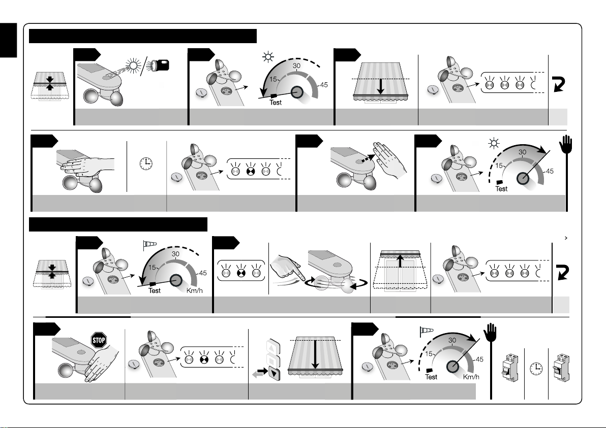
Product operation is based on real-time readings of variations in wind speed and sun-
light intensity (TGWS only). When the climatic sensor readings violate their thresholds
(either above or below), the sensor transmits a radio signal to the motor’s automation
receiver, which in turn activates an Up or Down manoeuvre, depending on the type
of signal received (above or below the threshold). Up to 3 sensors can be installed
on a single automation system, thus enabling data acquisition at different points of the
environment.
PRELIMINARY INSTALLATION CHECKS
AND PRODUCT APPLICATION LIMITS
2
•Read the technical specifications provided in the chapter “Product technical specifica-
tions” to check the application limits of the sensor.
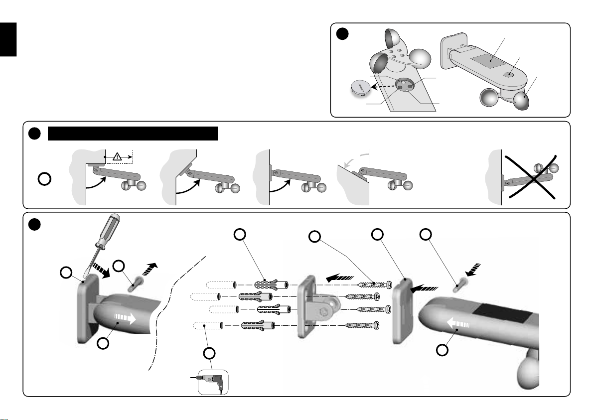
•(fig. 1) In favourable conditions (unobstructed field), the transmission range of the sen-
sor is 100 m, however, since the sensor is intended to protect the awning, it is advis-
able to install it at most 10-20 m away from the motor. We also recommend check-
ing that the zone is clear of other wireless devices transmitting on the same frequency,
such as alarms, wireless headsets, etc.: they can further reduce the range or even
block the transmissions of the device to the motor.
•Make sure that the sensor’s installation zone satisfies the following requisites:
– (fig. 2) it must allow for full and direct sunlight exposure of the sun sensor surface
(TGWS only) and the photovoltaic power cell; never install the product in zones
subject to shade from awnings, trees, balconies etc. or below a source of intense
artificial light;
– (fig. 3) the area must ensure exposure of the wind sensor blades to the same venti-
lation as that applied on the sun awning to be automated.

5– English
EN
•Since the sensor’s body is jointed and can be oriented as desired, ti can also be in-
stalled to sloping surfaces. The tilt range is given in the Quick reference guide (Step 1
- Fig. B - phase 1).
•Ensure that the surfaces selected for installation are solid and guarantee a stable fixture.
•Make sure that the sensor is protected against accidental impact.
PRODUCT INSTALLATION
3
For installation, fix the various parts of the product in numerical order as shown in the
Quick reference guide (Step1 - Fig. C). Then adjust the sensor body as shown in the
Quick reference guide (Step 1 - Fig. B - phase 1).
Make sure that the wind sensor blades are horizontal (Quick reference guide - Step 1 -
Fig. D).
ACTIVATION AND MEMORISATION
OF THE SENSOR IN THE MOTOR
RECEIVER
4
CAUTION! - Prior to proceeding with any memorisation activity, first
activate the sensor (Quick guide - Step 2):
01.Turn the two trimmers “Sun” and “Wind” anti-clockwise to position “30”.
02.Press and hold the “P1” button for 4 seconds: the green LED “L1” will flash 6 times.
Important! This procedure must only be performed once as an initial
activation.
As for any other transmitter, the climatic sensor’s radio code must be memorized in the
receiver of the motor it controls, so that the sensor can send wireless commands.
To memorise the sensor follow the “Mode I” procedure described in the manual of the
tubular motor or associated receiver. Alternatively the following memorisation procedure
can be used.
•Procedure for memorising the sensor using an already memorised
transmitter
Caution:
This procedure (Quick reference guide - Step 3) may only be used if one or more radio
codes have already been memorized in the tubular motor.
01.Caution! – Make sure that the “Sun” (TGWS only) and “Wind” trimmers are
not set to “Test”. Turn them to another value if necessary.
02.Hold down for 10 seconds button “P1” of the new sensor and then release it.
03.Press the button of a previously memorized transmitter 3 times (slowly).
04.Press the again the button “P1” of the sensor to be memorized for at least 2 sec-
onds and check that the motor emits 3 signals(*) (= memorization successful).
Note – If the memory is full, the motor emits 6 signals(*), notifying the user that
memorisation of the new sensor is not possible.
(*) Note – The signals correspond to small movements.
•Checking that the sensor has been memorized
01.Shut off electrical power to the motor; wait for 2 seconds and restore power.
02.Send a command to the system and, while it is executing, press sensor button P1 for
at least 2 seconds. Now, check that the motor immediately stops (= sensor memorized).
CALIBRATING THE SENSORS
5
Once the sensors have been memorized, they must be calibrated, as follows.
Note to the procedures – When the trimmer is set to “Test”, the system sets the sen-
sor threshold to a minimum, so that it can react to events without the delays employed
in normal operation. This serves to quickly check that the system is behaving properly.
•Calibrating the sun sensor (TGWS only - not available on TGW)
(Quick reference guide - Step 4)
01.Illuminate the sun sensor with bright sunlight; if the day is very cloudy, use a lamp.
The brightness of the light striking the sensor must be at least 1Klux.
02.Turn the “Sun” trimmer CCW to “Test”.
03.Check that the motor lowers the awning and the green Led flashes briefly several
times (= threshold exceeded).
04.Now obscure the sun sensor with a hand or a black cloth which lets no light
through, and after 15 seconds or so, check:
a) the Led must flash alternately red and green alternately briefly several times (=
return to within threshold); b) the sensor must tell the motor to raise the awning.

English – 6
EN
EN
05.Remove your hand or the cloth.
06.Now, turn the “Sun” trimmer CW to the desired setting(*), outside the “Test”
zone.
(*) - This value can be changed later with the procedure and values given in chapter 6.
•Calibrating the wind sensor (Quick reference guide - Step 5)
01.Turn the “Wind” trimmer CCW to “Test”.
02.Wait for the red/green leds to stop flashing briefly and alternately. Rotate the
wind sensor blades and check: a) the motor must raise the awning; b) the sensor
must prevent the motor receiving any other commands (thus protecting the awning
against the wind); c) the Led must flash red briefly several times (= threshold ex-
ceeded).
03.Now stop the blades and after which: a) the Led must flash briefly red and green
alternately several times (= return to within threshold); b) the sensor must deactivate
the protection function: send a transmitter command to the motor, the awning should
respond.
04.Now, turn the “Wind” trimmer CW to the desired setting(*), outside the “Test”
zone.
(*) - This value can be changed later with the procedure and values given in chapter 6.
SETTING THE CLIMATIC SENSOR
TRIP VALUE
6
You must set the “trip value” of the climatic sensors, i.e. a value above (or below)
which the sensor trips and sends a wireless command to the receiver in which it is mem-
orized.
Note - During normal operation of the sun (TGWS only) and wind sensors, led “L1”
is off, even when the unit is transmitting control signals.
• Operation of the “WIND” setpoint (fig. 4) – The wind sensor, measures the
windspeed in real time; when it exceeds the setpoint, after 3 seconds the sensor trans-
mits the Up command to the motor and blocks manual controls.
When the windspeed drops below the setpoint, after 4 minutes the sensor sends a sig-
nal to the motor, thus releasing it to receive manual commands. After 10 minutes (about)
automatic operation is restored.
• Operation of the “SUN” setpoint (fig. 5) – The sun sensor (TGWS only)
measures the brightness of the sunlight in real time; when it exceeds the setpoint, after 2
minutes the sensor sends the Down command to the motor.
When the brightness drops below the setpoint value, after 15 minutes the sensor sends
the Up command to the motor.
Setting the “Sun” and “Wind” sensor setpoints (fig. E)
01.(TGWS only) Turn the “Sun” trimmer to the desired setting. Important – Set-
ting the trimmer to its maximum value (at the end of its CW rotation) disables the
Sun sensor.
01 0302 04
Km/h
wind
sun
klx
01
su
03
wi
...
04
Km/h
Km
...
02
klx
“L1” (green-red-)“L1” (green-red-)
fast flashingfast flashing
E
Desired value... Series of flashes Desired value... Series of flashes
(TGWS only)

7– English
EN
02.Wait for the changes to be confirmed by the leds flashing alternately.
03.Turn the “Wind” trimmer to the desired setting.
04.Wait for the changes to be confirmed by the leds flashing alternately.
DIAGNOSTICS
7
You can enable “DIAGNOSTICS mode” at any time to check whether the weather con-
ditions at the time are above or below the setpoint.
To enable diagnostics, press “P1” briefly (< 2 seconds). Now watch the Led and check
the sequences of flashes against Table A.
Note – If several thresholds are exceeded during normal operation (for example, both
the sun and wind thresholds), the diagnostics signals only the one which has the lower
number in Table A.
Caution! – Diagnostics mode can only be used for reading signals off
the Leds, not for operating the awning.
Table A - Led diagnostics signals
1Red Led flashing (3 short flashes) =
The wind setpoint has been exceeded
2Green Led flashing (3 short flashes) =
The sun setpoint has been exceeded
(TGWS only – not available on TGW)
3Led green and red led flashing alternately =
No setpoint exceeded
BASIC TROUBLESHOOTING
8
If the wind or sunlight are stronger than their respective trip values
but the motor does not respond as it should, check that the sensor is pow-
ered correctly and memorized in the motor’s receiver (see chapters 3 and 4). If this does
not solve the problem, check the operation of the sensor by running the diagnostics de-
scribed in chapter 7.
PRODUCT DISPOSAL
9
This product is an integral part of the automation and must therefore be scrapped togeth-
er with it, in the same way as indicated in the automation’s instruction manual.
Dispose of the product packaging material in compliance with established local legis-
lation.

English – 8
EN
EN
TECHNICAL CHARACTERISTICS
OF THE PRODUCT
10
lPower: completely autonomous solar power with 64 mWp photovoltaic cell
lFrequency: 433.92 MHz with integral antenna
lRadiated power(*): approx. 1 mW (erp). In optimal conditions this corresponds
to a range of approx. 100 m in open field or 20 m inside buildings
lProtection rating: IP 34
lOperating temperature: - 20°C to + 55°C
lDimensions mm: (volume) 114 x 225 x 85 (H)
lWeight: 230 g
“Sun” sensor (TGWS only)
lRange: 3 to 64 klux
lSetting: 5 to 60 klux
“Wind” sensor
lRange: 0 to 125 kph
lSetting: 5 to 60 kph
Notes on technical specifications:
– (*) The transmitter’s range may be affected by other devices operating nearby and at
the same frequency (e.g. wireless headsets, alarm systems, etc.), which interfere with
it. In the event of strong interference, the manufacturer cannot guarantee the effective
range of their devices.
– All technical specifications stated herein refer to an ambient temperature of 20° C (±
5° C).
– The manufacturer reserves the right to apply modifications to the product at any time
when deemed necessary, maintaining the same intended use and functionality.
EC DECLARATION OF CONFORMITY
11
Nice S.p.A. hereby declares that the products: TGWS and TGW conform to the essential
requirements and other applicable provisions of directive 1999/5/EC.
The CE declaration of conformity can be viewed and printed out at www.niceforyou.
com or may be requested directly form Nice S.p.A.
7 May 2014 Mr. Mauro Sordini
(Chief Executive Officer)

1– Italiano
IT
82° max
82°
82° 82°
1
4
3
2
8
1
57 9
6
GUIDA RAPIDA
TGWS/TGW
Passo 1 - Installazione e Collegamenti elettrici
10
sensore
Vento
Vento
Led “L1”
tasto “P1”
Sole
sensore Sole
(solo per TGWS)
cella fotovoltaica
(solo TGWS)
A
B
C

Italiano – 2
IT
Passo 3 - Memorizzazione del sensore e verifica della memorizzazione
33
Old
01 02 03
“P1”“P1”
X 3
“P1”
01 02
“P1”
10
sec.
2
sec.
2
sec. ON
OFF
01
03
X
3
02
(verifica della
memorizzazione)
Mantenere premuto
Movimenti (3) Premere 1 volta (Salita) Premere 1 volta per almeno 2 secondi
(Stop manovra)
Attendere
Rilasciare Premere 3 volte Premere 1 volta per almeno 2 secondi
D
Passo 2 - Attivazione del sensore
sun
klx
01 02
wind
“P1”“L1”
4
sec.

3– Italiano
IT
01 02
wind
03 04 wind
2
sec. ON
OFF
01
w
in
...
...
04
w
in
“L1” (verde-rosso-)
“L1” (rosso)
lampeggi veloci
lampeggi veloci
01
06
≥ 1Klux
sun
klx
...
...
02 sun
klx
u
x
02
06
su
15
sec.
03
04 05
Illuminare il sensore Ruotare trimmer su “Test”
Coprire il sensore dopo circa
15 secondi
Ruotare trimmer su “Test”
Fermare le pale Attendere ~10 secondi per avere la
serie di lampeggi Premere 1 volta (Discesa) Ruotare trimmer su altro valore
Attendere fine lampeggi e azionare le pale Salita Serie di lampeggi
Serie di lampeggi Scoprire il sensore Ruotare trimmer su altro valore
Discesa Serie di lampeggi
“L1” (verde)
lampeggi veloci
“L1” (verde-rosso-)
lampeggi veloci
Passo 4 - Taratura del sensore “Sole” (solo per il modello TGWS)
Passo 5 - Taratura del sensore “Vento”

Italiano – 4
IT
AVVERTENZE GENERALI
ATTENZIONE!
•Istruzioni importanti per la sicurezza: attenersi alle istruzioni in
quanto un’installazione impropria può provocare gravi ferite.
•
Per la sicurezza delle persone è importante rispettare queste istruzioni.
•Conservare queste istruzioni.
•Tutte le operazioni di installazione, di collegamento, di programma-
zione e di manutenzione del dispositivo devono essere effettuate
esclusivamente da un tecnico qualificato!
•Il sensore non è da considerarsi un dispositivo di sicurezza che eli-
mina i guasti alla tenda per effetto del vento forte (di fatto, un ba-
nale blackout elettrico renderebbe impossibile il ritiro automatico
della tenda). Il sensore va considerato parte di un’automazione uti-
le alla salvaguardia della tenda e al confort per il suo uso.
•Il produttore declina ogni responsabilità per i danni materiali che dovessero verificarsi
a causa di eventi atmosferici non rilevati dai sensori del dispositivo.
•Non aprire il guscio di protezione del dispositivo perché contiene circuiti elettrici non
soggetti a manutenzione.
•Non eseguire modifiche su nessuna parte del dispositivo. Operazioni non permesse
possono causare solo malfunzionamenti. Il costruttore declina ogni responsabilità per
danni derivanti da modifiche arbitrarie al prodotto.
•Non mettere il dispositivo vicino a fonti di calore né esporlo a fiamme libere. Tali azio-
ni possono danneggiarlo ed essere causa di malfunzionamenti.
•Il prodotto non è destinato ad essere usato da persone (bambini compresi) le cui ca-
pacità fisiche, sensoriali o mentali siano ridotte, oppure con mancanza di esperienza
o di conoscenza.
•Controllare che bambini non giochino con il prodotto.
•Il dispositivo è alimentato da una cella fotovoltaica. Poiché nelle ore diurne questa
deve essere esposta costantemente alla luce solare, assicurarsi che la sua superficie
sensibile sia sempre pulita e libera da foglie, neve o altro: pulire la superficie con un
panno morbido e umido, evitando sostanze contenenti alcool, benzene, diluenti o si-
milari.
•Maneggiare con cura il prodotto evitando azioni che possano danneggiarlo come,
ad esempio, schiacciamenti, urti, cadute, eccetera.
Istruzioni originali
ITALIANO DESCRIZIONE DEL PRODOTTO
E DESTINAZIONE D’USO
1
Il presente prodotto è un sensore climatico destinato agli impianti di automatizzazione
per tende da sole, tapparelle, lucernari e similari, che adottano centrali e motori tubo-
lari compatibili. Ogni altro uso è da considerarsi improprio e vietato! Il
produttore non risponde dei danni risultanti da un uso improprio del
prodotto, diverso da quanto previsto nel presente manuale.
Il sensore è dotato di un trasmettitore radio integrato e di un’alimentazione autonoma
a energia solare, fornita da una cella fotovoltaica integrata; durante la notte il sensore
sfrutta l’energia residua accumulata di giorno, senza la necessita, dunque, di essere
collegato alla rete elettrica. Le altre parti che compongono il dispositivo sono indicate
nella Guida rapida (Passo 1 - fig. A).
Il funzionamento del prodotto si basa sul rilevamento in tempo reale della velocità del
vento e dell’intensità della luce solare (solo per il modello TGWS).
Quando il valore rilevato dai sensori climatici supera (verso l’alto o verso il basso) la
soglia d’intervento impostata, il sensore trasmette un “segnale radio” al ricevito-
re del motore, che a sua volta, comanda una manovra di Salita o di Discesa, in base
al tipo di segnale ricevuto (sopra o sotto la soglia). In un’automazione possono essere
installati fino a 3 sensori: questo consente di controllare più punti nell’ambiente.
VERIFICHE PRELIMINARI
ALL’INSTALLAZIONE E LIMITI
D’IMPIEGO DEL PRODOTTO
2
•Leggere i dati tecnici riportati nel capitolo “Caratteristiche tecniche del prodotto” per
valutare i limiti d’impiego del sensore.
•(fig. 1) Anche se in condizioni favorevoli (cioè in campo aperto) la portata radio del
sensore è in grado di arrivare fino a 100 m, considerando che il sensore rappresenta
una protezione per la tenda, si consiglia di installare il sensore a una distanza mas-
sima di 10-20 m dal motore. Inoltre si consiglia di accertarsi che nella zona non vi
siano altri dispositivi radio che trasmettano alla stessa frequenza come, ad esempio,
allarmi, radiocuffie, eccetera: l’azione di questi dispositivi potrebbe ridurre ulterior-
mente la portata o addirittura bloccare la comunicazione tra il sensore e il motore.
•Accertarsi che il luogo prescelto per l’installazione del sensore abbia i seguenti requisiti:
– (fig. 2) deve permettere l’insolazione piena e diretta della superficie del sensore sole
(solo per il modello TGWS) e della cella fotovoltaica che alimenta il prodotto; non
installare il prodotto nelle zone d’ombra create da tende, alberi, balconi ecc. o sotto una

5– Italiano
IT
sorgente artificiale di luce intensa;
– (fig. 3) deve permettere l’esposizione delle pale del sensore vento alla stessa venti-
lazione a cui è soggetta la tenda da sole che si desidera automatizzare.
•Poiché il corpo del sensore è snodato e orientabile, è possibile fissare il prodotto an-
che su una superficie inclinata. I limiti dell’inclinazione sono riportati nella Guida rapi-
da (Passo 1 - Fig. B - fase 1).
•Accertarsi che la superficie prescelta per l’installazione sia di materiale solido e possa
garantire un fissaggio stabile.
•Accertarsi che il sensore sia collocato in una posizione protetta da urti accidentali.
INSTALLAZIONE DEL PRODOTTO
3
Per eseguire l’installazione, fissare le varie parti del prodotto seguendo l’ordine numerico
riportato nella Guida rapida (Passo 1 - Fig. C). Infine orientare il corpo del sensore come
mostrato nella Guida rapida (Passo 1 - Fig. B - fase 1).
Accertarsi che le pale del sensore vento siano su un piano orizzontale (Guida rapida -
Passo 1 - Fig. D).
ATTIVAZIONE E MEMORIZZAZIONE
DEL SENSORE
NEL RICEVITORE DEL MOTORE
4
ATTENZIONE! - Prima di procedere con qualsiasi memorizzazione è
necessario attivare il sensore (Guida rapida - Passo 2):
01.Ruotare i due trimmer “Sole” e “Vento” in senso antiorario portandoli nella posi-
zione “30”.
02.Mantenere premuto per 4 secondi il tasto “P1”: il Led verde “L1” effettua 6 lam-
peggi.
Importante! Questa procedura va eseguita solo una volta come pri-
ma attivazione.
Come per qualsiasi trasmettitore, anche per il presente sensore climatico è necessario
memorizzare il suo codice radio nel ricevitore del motore da comandare, in modo che
il sensore possa inviare i comandi “via radio”. Per memorizzare il sensore occorre uti-
lizzare la procedura “Modo I” descritta nel manuale del motore tubolare o del ricevi-
tore abbinato. In alternativa è possibile usare anche la seguente procedura di memo-
rizzazione.
•Procedura di memorizzazione del sensore con un trasmettitore già
memorizzato
Avvertenza:
Questa procedura (Guida rapida - Passo 3) può essere usata soltanto se nel motore tu-
bolare sono già memorizzati uno o più codici radio.
01.Attenzione! – Accertarsi che i trimmer “Sole” (solo per il modello TGWS)
e “Vento” non siano posizionati sul valore “Test”. Eventualmente ruotarli su un al-
tro valore.
02.Mantenere premuto per 10 secondi il tasto “P1” del nuovo sensore da memorizzare
poi rilasciare il tasto.
03.Premere per 3 volte (lentamente) il tasto di un vecchio trasmettitore già memorizzato
nel motore.
04.Premere di nuovo il tasto “P1” del sensore da memorizzare per almeno 2 secondi
e accertarsi che il motore emetta 3 segnalazioni(*) (= memorizzazione avvenuta).
Avvertenza – Se la memoria è piena, il motore emette 6 segnalazioni(*) che in-
dicano l’impossibilità di memorizzare il nuovo sensore.
(*) Nota – Le segnalazioni corrispondono a dei piccoli movimenti.
•Verifica dell’avvenuta memorizzazione del sensore
01.Togliere l’alimentazione elettrica al motore; attendere 2 secondi e ridare l’alimenta-
zione.
02.Comandare una manovra e, durante la sua esecuzione, premere il tasto P1 sul sen-
sore per almeno 2 secondi. Quindi, accertarsi che il motore arresti immediatamen-
te la manovra (= sensore memorizzato).
TARATURA DEI SENSORI
5
Al termine della procedura di memorizzazione è necessario tarare i sensori effettuando
le seguenti procedure.
Nota alle procedure – Quando il trimmer è posizionato sulla funzione “Test” il si-
stema imposta la soglia del sensore al minimo, in modo che quest’ultimo reagisca agli
eventi in tempo reale, senza rispettare i tempi di attesa previsti per il funzionamento nor-

Italiano – 6
IT
male. Ciò permette di verificare velocemente il comportamento del sistema.
•Taratura del sensore sole (solo per il modello TGWS - funzione non
presente nel modello TGW)
(Guida rapida - Passo 4)
01.Fare in modo che il sensore sole venga illuminato dalla luce solare intensa; se il
cielo è particolarmente nuvoloso e coperto, utilizzare una lampada. In ogni caso,
l’intensità della luce deve essere di almeno 1Klux.
02.Ruotare il trimmer “Sole” in senso antiorario, fino a raggiungere la posizione
“Test”.
03.Accertarsi che il motore comandi la Discesa della tenda e che il Led verde emetta
una serie di lampeggi brevi (= superamento della soglia).
04.Quindi, oscurare il sensore sole con una mano o con un telo nero opaco alla luce
e dopo circa 15 secondi accertarsi che:
a) che il Led esegua una serie di lampeggi brevi di colore rosso e verde alternati
(= fine superamento soglia); b) che il sensore invii al motore un comando di Salita.
05.Rimuovere la mano o il telo utilizzati per oscurare il sensore.
06.Infine, ruotare il trimmer “Sole” in senso orario, portandolo su un valore desidera-
to(*), fuori dalla zona “Test”.
(*) - Questo valore è modificabile in un secondo momento utilizzando la procedura e
le informazioni riportate nel capitolo 6.
•Taratura del sensore vento (Guida rapida - Passo 5)
01.Ruotare il trimmer “Vento” in senso antiorario, fino a raggiungere la posizione
“Test”.
02.Attendere la fine dei lampeggi brevi di colore rosso e verde alternati. Mettere in
movimento le pale del sensore vento e accertarsi che: a) il motore comandi la Sa-
lita della tenda; b) che il sensore blocchi la possibilità di comandare il motore con
qualsiasi altro comando (protezione della tenda dal vento); c) che il Led emetta
una serie di lampeggi brevi di colore rosso (= superamento della soglia).
03.Quindi, fermare le pale e attendere che: a) il Led emetta una serie di lampeggi
brevi di colore rosso e verde alternati (= fine superamento soglia); b) che il senso-
re sblocchi la protezione della tenda dal vento: a tal proposito, dare un comando
con il trasmettitore e verificare che la tenda risponda a questo comando.
04.Infine, ruotare il trimmer “Vento” in senso orario, portandolo su un valore deside-
rato(*), fuori dalla zona “Test”.
(*) - Questo valore è modificabile in un secondo momento utilizzando la procedura e
le informazioni riportate nel capitolo 6.
IMPOSTAZIONE DELLE SOGLIE DI
INTERVENTO DEI SENSORI CLIMATICI
6
La regolazione dei sensori climatici presenti nel prodotto serve per impostare in ciascu-
no di loro la “soglia d’intervento”, ovvero un valore desiderato al di sopra del
quale (o al di sotto del quale) il sensore interviene inviando un segnale radio al ricevi-
tore nel quale è memorizzato.
Nota - Durante il normale funzionamento del sensore sole (solo per il modello
TGWS) e del sensore vento il Led “L1” rimane sempre spento, anche nei momenti in
cui il dispositivo trasmette i comandi.
• Funzionamento della soglia “VENTO” (fig. 4) – Il sensore vento rileva e mi-
sura in tempo reale la velocità del vento; quando questa supera il valore impostato, dopo
3 secondi il sensore trasmette al motore il comando di Salita e blocca i comandi manuali.
Quando l’azione del vento termina e scende sotto il valore impostato, dopo 4 minuti
01 0302 04
Km/h
wind
sun
klx
01
su
03
wi
...
04
Km/h
Km
...
02
klx
“L1” (verde-rosso-)“L1” (verde-rosso-)
lampeggi velocilampeggi veloci
E
Valore desiderato... Serie di lampeggi Valore desiderato... Serie di lampeggi
(Solo per il modello TGWS)

7– Italiano
IT
il sensore trasmette questa condizione al motore, ripristinando la possibilità di inviare i
comandi manuali. Dopo 10 minuti (circa) viene ripristinato il funzionamento automatico.
• Funzionamento della soglia “SOLE” (fig. 5) – Il sensore sole (solo per il
modello TGWS) rileva e misura in tempo reale l’intensità della luce solare; quando
questa supera il valore impostato, dopo 2 minuti il sensore trasmette al motore il co-
mando di Discesa.
Quando l’intensità della luce solare scende sotto il valore impostato, dopo 15 minuti il
sensore trasmette al motore il comando di Salita.
Procedura per impostare la soglia di intervento del sensore “Sole” e
“Vento” (fig. E)
01.(Solo per il modello TGWS) Ruotare il trimmer “Sole” fino a posizionarlo sul
valore desiderato. Importante – Se il trimmer viene impostato sul valore massi-
mo (cioè al termine della corsa, procedendo in senso orario), viene escluso il fun-
zionamento del sensore sole.
02.Attendere la conferma dell’avvenuta modifica attraverso il lampeggio alternato del
led.
03.Ruotare il trimmer “Vento”, fino a posizionarlo sul valore desiderato.
04.Attendere la conferma dell’avvenuta modifica attraverso il lampeggio alternato del
led.
DIAGNOSTICA
7
In qualsiasi momento è possibile attivare la “modalità DIAGNOSTICA” per verificare se
l’intensità del fenomeno atmosferico che si sta manifestando in quell’istante è al di sotto
o al di sopra della soglia.
Per attivare la diagnosi premere brevemente il tasto “P1” (< 2 secondi). Quindi os-
servare la successiva segnalazione del Led e leggerne il significato nella Tabella A.
Nota – Se durante il normale funzionamento vengono superate più soglie (ad esempio
quella del sole e del vento), il sistema diagnostico segnala tra queste solo quella che
nella Tabella A è identificata con il numero più basso.
Attenzione! – La modalità “diagnostica” provoca solo la segnalazio-
ne sul Led e non il comando della tenda.
Tabella A - Segnalazioni diagnostiche del Led
1Led rosso lampeggiante (3 lampeggi lenti) = È stata superata
la soglia d’intervento “vento”
2Led verde lampeggiante (3 lampeggi lenti) = È stata superata
la soglia d’intervento “sole” (solo per il modello TGWS - fun-
zione non presente nel modello TGW)
3Led verde e rosso lampeggianti in modo alternato = Non
è stata superata nessuna soglia d’intervento
COSA FARE SE...
8
Se l’intensità del vento o della luce solare è superiore alla soglia im-
postata ma il motore sembra non eseguire le manovre come dovreb-
be, verificare che il sensore sia alimentato correttamente e che sia memorizzato corret-
tamente nel ricevitore del motore da comandare (vedere il capitolo 3 e 4). Se questo
non risolve il problema, controllare il corretto funzionamento del sensore eseguendo la
diagnosi riportata nel capitolo 7.
SMALTIMENTO DEL PRODOTTO
9
Questo prodotto è parte integrante dell’automazione, e dunque, deve essere smaltito
insieme con essa, applicando gli stessi criteri riportati nel manuale istruzioni dell’auto-
mazione.
Il materiale dell’imballaggio del prodotto deve essere smaltito nel pieno rispetto della
normativa presente a livello locale.
This manual suits for next models
1
Table of contents
Languages:
Popular Accessories manuals by other brands

Daga
Daga Softy Fleece Directions for use

Sony
Sony BRAVIA DMX-NV1 Attachment guide

Johnson Controls
Johnson Controls WRZ-SST-110 installation instructions

Joie
Joie A1112LABLK000 instruction manual

X10
X10 HawkEye MS13A Set up and operating instructions

Amana
Amana EXTENDED WALL SLEEVE installation instructions