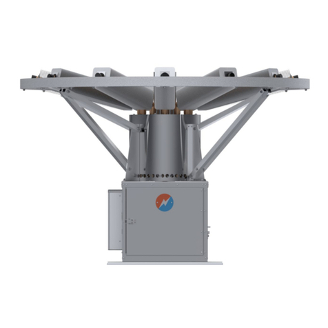
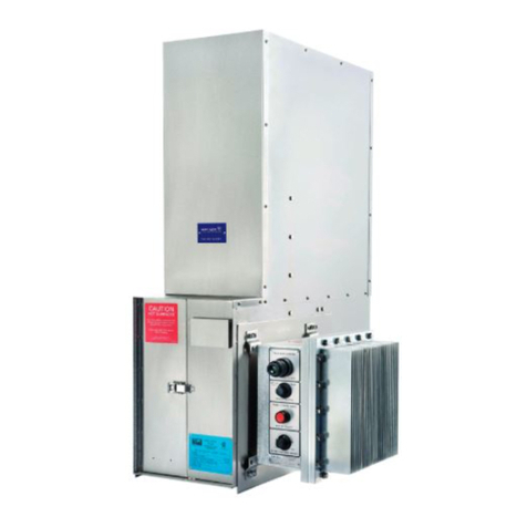
Global MX PrimeGen User manual

Global Power Technologies /www.globalte.com
5024343
CONFORMS TO ANSI/CAN/UL/ULC STD 2200
MX PrimeGen
Power Generator
INSTALLATION OPERATION AND
MAINTENANCE MANUAL


Table of Contents
1COPYRIGHT, LIABILITY, AND CONTACT INFORMATION ..........................................................1
2IMPORTANT SAFETY INSTRUCTIONS ......................................................................................2
2.1 MANUAL ICONS AND SAFETY BANNERS......................................................................................4
2.2 TECHNICALLY QUALIFIED PERSONNEL ........................................................................................4
2.3 BATTERY SAFETY .........................................................................................................................4
2.4 START-STOP OPERATIONS...........................................................................................................5
3PRODUCT INFORMATION ......................................................................................................6
3.1 TERMS AND ACRONYMS .............................................................................................................7
3.2 DATA PLATE ................................................................................................................................8
4ASSEMBLY AND INSTALLATION..............................................................................................9
4.1SITE PREPARATION......................................................................................................................9
4.1.1 LOCATION AND ACCESS ..............................................................................................................9
4.1.2 FUEL SUPPLY .............................................................................................................................10
4.1.3 STANDARD SPECIFICATIONS FOR GASEOUS FUEL .....................................................................10
4.2 UNPACKING AND LIFTING .........................................................................................................11
4.3 ACCESS PANELS.........................................................................................................................13
4.4 ASSEMBLY AND INSTALLATION .................................................................................................14
4.4.1 BATTERIES.................................................................................................................................15
4.4.2 RADIATOR GLYCOL ....................................................................................................................16
4.4.3 FUEL SUPPLY .............................................................................................................................17
4.4.4 WIRING CONNECTIONS.............................................................................................................17
4.4.5 WIND SHIELD ADJUSTMENT......................................................................................................20
5START-UP.............................................................................................................................21
5.1 LOCAL START-UP .......................................................................................................................21
5.2 EXTERNAL BATTERY CHARGE AND COLD AMBIENT START........................................................22
5.3 REMOTE START-UP ...................................................................................................................23
6OPERATION .........................................................................................................................24
6.1 USER INTERFACE SETTINGS.......................................................................................................24
6.1.1 ESD BUTTON .............................................................................................................................24
6.1.2 LOC/REM SWITCH – LOCAL / REMOTE MODES .........................................................................24
6.1.3 AUTO/MAN SWITCH – AUTO-STANDBY / MANUAL MODES .....................................................25
6.1.4 LOCAL ON/OFF ..........................................................................................................................26
6.1.5 LED STATUS LIGHTS...................................................................................................................26
6.1.6 START AND STOP BUTTONS ......................................................................................................26
6.2 LED DISPLAY ..............................................................................................................................26
6.2.1 DISPLAY SCREENS......................................................................................................................27

7REMOTE MONITORING........................................................................................................32
7.1 REMOTE MONITORING THROUGH DRY CONTACTS (SCADA) ....................................................32
7.2 REMOTE MONITORING THROUGH MODBUS ............................................................................33
7.3 REMOTE MONITORING THROUGH IOT .....................................................................................36
7.3.1 LOG-IN INSTRUCTIONS..............................................................................................................36
8SHUTDOWN.........................................................................................................................39
8.1 SHUTDOWN ..............................................................................................................................39
8.2 EMERGENCY SHUTDOWN (ESD)................................................................................................39
9SERVICE AND MAINTENANCE...............................................................................................41
9.1 RECOMMENDED MAINTENANCE AND INTERVALS....................................................................41
9.1.1 STANDBY OIL SYSTEMS .............................................................................................................42
9.1.2 SYSTEMS WITH EXTENDED OIL RESERVOIR...............................................................................43
9.2 SYSTEM CHECK..........................................................................................................................44
9.3 SYSTEM SHUTDOWN AND LOCK OUT FOR MAINTENANCE.......................................................44
9.4 FUEL TRAIN ASSEMBLY LEAK CHECK .........................................................................................44
9.5 AIR SYSTEM FILTERS CHECK ......................................................................................................45
9.6 BATTERY INSPECTION ...............................................................................................................46
9.7 OIL SYSTEM CHECK....................................................................................................................47
9.7.1 CHECK OIL CATCH CAN..............................................................................................................48
9.7.2 CHECK OIL LEVELS .....................................................................................................................48
9.8 OIL CHANGES ............................................................................................................................48
9.9 COOLANT SYSTEM CHECK .........................................................................................................49
9.10 COOLANT CHANGES..................................................................................................................49
9.11 O2 SENSOR REPLACEMENT .......................................................................................................50
9.12 ENGINE VALVE ADJUSTMENT....................................................................................................50
9.13 IGNITION SYSTEM REPLACEMENT.............................................................................................50
9.14 COMPRESSION CHECK...............................................................................................................50
9.15 ENGINE OVERHAUL...................................................................................................................50
10 STORAGE .............................................................................................................................51
10.1 BATTERY STORAGE....................................................................................................................51
11 MAINTENANCE AND COMMISSIONING SPARES ...................................................................52
11.1 STANDBY OIL CAPACITY SYSTEMS .............................................................................................52
11.2 EXTENDED RUN OIL CAPACITY SYSTEMS...................................................................................53
11.3 COMMISSIONING AND RECOMMENDED SPARES .....................................................................54
11.4 INVERTER FOR 12 VDC TO 120VAC EXTERNAL POWER SUPPLY (OPTION) ................................54
12 TROUBLESHOOTING ............................................................................................................55
12.1 ALARM CODES...........................................................................................................................55
13 PARTS LIST........................................................................................................................... 58

14 EMISSION-RELATED WARRANTY..........................................................................................62
14.1 WARRANTY PERIOD ..................................................................................................................62
14.2 COMPONENTS COVERED ..........................................................................................................62
14.3 LIMITED APPLICABILITY .............................................................................................................63
14.4 WARRANTY CLAIMS ..................................................................................................................63
APPENDIX A — PRODUCT SPECIFICATIONS .....................................................................................64
APPENDIX B — WEIGHT AND DIMENSIONS.....................................................................................65
Table of Figures
Figure 3-1 – Data Plate............................................................................................................................8
Figure 3-2 – MX Model Tree ...................................................................................................................8
Figure 4-1– Anchor Hole Layout..............................................................................................................9
Figure 4-2 – Slinging and Lifting Diagram..............................................................................................12
Figure 4-3 – Lifting with Forklift............................................................................................................12
Figure 4-4 – Location of Access Panel Fasteners...................................................................................13
Figure 4-5 – Assembly...........................................................................................................................14
Figure 4-6 – Batteries and Connectors..................................................................................................15
Figure 4-7 – Battery Wiring Terminations.............................................................................................16
Figure 4-8 – Location of Coolant Reservoir and Expansion Tank...........................................................17
Figure 4-9 – Holes for Customer Connections.......................................................................................18
Figure 4-10 – Customer Wiring Terminations (Single Phase Systems) ..................................................18
Figure 4-11 – Customer Terminations (3 Phase Systems) .....................................................................19
Figure 4-12 – Wind Shield Recommended Gap from Radiator Shroud Cover .......................................20
Figure 5-1 – Operation Switches...........................................................................................................21
Figure 5-2 – Main System and Battery Charger Breakers (Single Phase)...............................................21
Figure 5-3 – Breakers Located Inside the Electrical Panel Enclosure (Single Phase) .............................22
Figure 5-4 – Breakers Located Inside the Electrical Panel Enclosure (3 Phase).....................................22
Figure 5-5 – Main System and Battery Charge Breaker (3 Phase).........................................................22
Figure 6-1 – Operation Switches...........................................................................................................24
Figure 6-2 – Alternate Pump Button Location ......................................................................................26
Figure 6-3 – LED Display........................................................................................................................27
Figure 7-1 – Cellular Modem Located in the Electrical Enclosure .........................................................36
Figure 7-2 – Log-in Page for Remote Monitoring System......................................................................37
Figure 7-3 – Remote Monitoring System Dashboard ............................................................................38
Figure 9-1 – Engine Air Intake Figure 9-2 – Engine Air Circulation....................................................45
Figure 9-3 – MX Batteries .....................................................................................................................46
Figure 9-4 – Standby Oil Configuration .................................................................................................47
Figure 9-5 – Long Run Oil Configuration ...............................................................................................48
Figure 9-6 – Coolant System .................................................................................................................49
Figure B-0-1 – MX Power Generator Dimensions .................................................................................65

List of Tables
Table 1 – MX Power Generator Fuel Specifications ..............................................................................11
Table 2 – Customer Wiring Connections (Single Phase Systems)..........................................................19
Table 3 – Customer Wiring Connections (3 Phase Systems) .................................................................20
Table 4 – MX Modbus Configuration Settings.......................................................................................33
Table 5 – MX Generator Modbus Map .................................................................................................34
Table 6 – Maintenance Schedule for Standby Oil Systems ...................................................................42
Table 7 – Maintenance Schedule for Systems with Extended Oil Reservoir .........................................43
Table 8 – Maintenance Materials for Standby Oil Capacity Systems ....................................................52
Table 9 – Maintenance Materials for Extended Run Oil Capacity Systems ...........................................53
Table 10 – Commissioning and Recommended Parts ...........................................................................54
Table 11 – Alarm Levels (First Digit)......................................................................................................55
Table 12 – Alarm Code Definitions........................................................................................................55

Global Power Technologies COPYRIGHT, LIABILITY, AND CONTACT INFORMATION
302672 Rev2 | MX PrimeGen 1
1COPYRIGHT, LIABILITY, AND CONTACT INFORMATION
This manual provides instructions for the installation, operation, performance, basic maintenance and
troubleshooting of the MX Power Generator. In the event of unforeseen or special problems, do not
take unauthorized remedial action. Contact GPT’s Customer Service department to obtain the
necessary information. All agreements, assurances, and legal relationships as well as all obligations of
GPT, shall be governed by the respective valid purchase contract which is not influenced by the content
of this document. For any technical issues or questions:
GLOBAL POWER TECHNOLOGIES – HEAD OFFICE
#16, 7875 – 57 Street SE Phone: 1-403-236-5556
Calgary, Alberta Fax: 1-403-236-5575
Canada T2C 5K7 Customer Service/Technical Support: 1-403-720-1190
Copyright
Copyright © 2022 by Global Power Technologies (GPT). All rights reserved. No part
of this manual may be reproduced without permission in writing from GPT, except
by a reviewer who may quote brief passages or reproduce illustrations in a review
with appropriate credit; nor may any part of this manual be reproduced, stored in
a retrieval system, or transmitted in any form or by any means – electronic,
photocopying, recording, or otherwise – without prior permission in writing from
GPT.
Liability
Liability The user is expressly warned to consider and adopt all safety precautions
that might be indicated by the activities herein and to avoid all potential hazards.
The user assumes all risks in connection with such instructions. GPT shall not be
liable for any special, consequential, exemplary, or other damages resulting, in
whole or part, from the user’s use of, or reliance upon this material.
Comments
GPT has compiled this publication with care, but GPT does not warrant that the
information in this publication is free of errors. Comments, criticisms, and
suggestions regarding the subject matter are invited. Any errors or omissions in the
data should be brought to the attention of GPT. If required, affected pages will be
revised and issued.

Global Power Technologies IMPORTANT SAFETY INSTRUCTIONS
302672 Rev2 | MX PrimeGen 2
2IMPORTANT SAFETY INSTRUCTIONS
SAVE THESE INSTRUCTIONS – This manual contains important instructions for the MX PrimeGen Power
Generator that should be followed during installation and maintenance of the generator and its
batteries. Read the following safety warnings before beginning assembly, installation, or maintenance
of the MX Power Generator.
1. Observe all prescribed accident prevention and safety rules. Do not perform work on the MX Power
Generator alone—make sure there is somebody else working with you.
2. The installation of the MX Power Generator must conform with local codes or, in the absence of
local codes, with CSA-B149.1 – Natural Gas and Propane Installation Code.
3. When installed, the MX Power Generator must be electrically grounded in accordance with local
codes, or in the absence of local codes, with CSA C22.1 – Canadian Electrical Code.
4. The MX Power Generator is not intended to be used in underground mines. Do not use the MX
system in underground mines.
5. Per local codes, the MX Power Generator shall be installed with a fuel shut-off valve. This is not
included in the base design but is included with the regulator option added. The shut-off valve must
be disconnected from the gas supply piping system during any pressure testing of that system at
test pressures more than 34 kPa (5 psi).
6. The MX Power Generator must be isolated from the gas supply piping system by closing its
individual manual shut-off valve during any pressure testing of the gas supply piping system at test
pressures equal to or less than 34 kPa (5 psi).
7. Do not use the MX Power Generator if any part has been under water. Immediately call a qualified
service technician to inspect and to replace any part of the control system, gas control and
generator that has been under water.
8. The MX Power Generator is designed to combust gaseous fuels which will result in combustion
products of heat, carbon dioxide and water vapour. It may contain traces of carbon monoxide,
unburnt hydrocarbons, and nitrous oxides. Emissions from combustion will depend on generator
set-up and operation as well as the composition of the gas feed. It is imperative that these
instructions be followed, and that gas supplied meets the gas specifications outlined in this manual.
9. The MX Power Generator must be mechanically installed according to the instructions contained
within this manual. It must be securely anchored to a non-combustible surface when installed.
10. Installation and repair must be performed by a qualified service person. The MX Power Generator
should be inspected before use and at least annually by a qualified service person. More frequent
cleaning may be required as necessary. It is imperative that control compartment, air intakes, and
circulating air passageways of the system are kept clean.
11. The MX Power Generator uses an internal combustion engine. Qualified service personnel should
have mechanical knowledge on how to maintain engine fuel, lubrication, ignition, and cooling
systems.
12. The MX Power Generator contains electrical, and gas related safety devices as identified
throughout this manual. Tampering or rendering inoperative any of these safety devices may result
in personal injury or death and possible damage to the equipment and is not permitted under any
circumstances.

Global Power Technologies IMPORTANT SAFETY INSTRUCTIONS
302672 Rev2 | MX PrimeGen 3
13. The MX Power Generator has some parts constructed from sheet metal. Every effort is made to
ensure that edges have been deburred when manufactured, however sharp edges may still exist.
Be cautious when handling. Wear gloves for safety.
14. Any guard or other protective device removed for servicing from the MX Power Generator must be
re-installed prior to operating the system.
15. The MX contains sub-systems that combust gaseous fuel and others that run high electrical loads,
all of which can pose high surface temperature hazards. Avoid exterior areas, as well as internal
components of the generator to avoid burns or clothing ignition when in operation or cooling down.
16. The MX Power Generator contains rotating parts, hot surface temperatures, and high voltages. It
also has remote start and stop capabilities. Do not begin work on the MX Power Generator unless
it is shut-off manually, switched to LOC mode, and locked out so that the system cannot be started
remotely or inadvertently. Follow the shutdown procedure on Section 7.1 of this manual.
17. The MX Power Generator uses natural gas or propane as fuel. In the event of a leak, there is a
possibility of a fire and explosion.
18. Lethal voltages are present in this system. The MX Power Generator has either 120/240 VAC
systems or 120/208 VAC as well as 24 VDC systems. Use accepted safety procedures for working on
all electrical circuits. Follow all local electrical safety regulations.
19. Study the MX Power Generator wiring diagrams and schematics before working on electrical
circuits and ensure that all tools used while working on electrical circuits are insulated.
20. The MX Power Generator contains batteries. Avoid touching live battery terminals and placing tools
on or near the batteries. These can provide dangerous voltages and currents, even when the system
is shut-off.
21. As soon as electrical cabinet doors are opened or terminal covers are removed, there is the danger
of contacting hazardous voltages. Any operations inside the cabinets or with exposed electrical
terminals must only be carried out by qualified electrical personnel. If in doubt, do not touch.
22. Sparking and arcing may occur if a wire is connected or disconnected with a heavy current flow.
Arcing can burn skin or eyes and damage equipment.
23. The MX Power Generator includes spark plug, which needs to be accessed during maintenance. Do
not touch the conductor of a spark plug while it is energized.
24. The MX Power Generator is not intended for use as emergency power.
25. Keep the MX Power Generator’s installation site clear and free from combustible materials,
gasoline, and other flammable vapours and liquids. Maintain the minimum clearances specified in
this manual.
26. Fuel supplied to the MX Power Generator must not contain liquids. Liquid hydrocarbons in the fuel
supply pose a risk of fire and may result in serious damage and danger to the operator.
27. Do not exceed the fuel pressure stamped on the MX Power Generator’s data plate without factory
approval.
28. The MX Power Generator exhaust can be very hot. Do not touch any of the exhaust components or
bring exposed skin near hot exhaust gases.

Global Power Technologies IMPORTANT SAFETY INSTRUCTIONS
302672 Rev2 | MX PrimeGen 4
29. When the MX Power Generator is operating, surface temperatures of the exhaust can approach
temperatures above 70°C (158°F). Avoid contact of skin and clothing with the surfaces of the
exhaust to avoid burns. The MX unit must be installed so that the risk of contact by people is
minimized.
30. The MX Power Generator is designed FOR OUTDOOR USE ONLY.
2.1 MANUAL ICONS AND SAFETY BANNERS
WARNING!
A banner with the word “WARNING!” below an icon with an exclamation point
within a red triangle contain important information that, if not adhered to, can cause
personal injury and/or property damage.
CAUTION!
A banner with the word “CAUTION!” below an icon with an exclamation point within
a red triangle contain important
information that, if not adhered to, can cause
damage to the MX Power Generator.
NOTE:
A banner with the word “NOTE:” contains supplemental information that provide
additional insight on specific topics throughout this manual.
2.2 TECHNICALLY QUALIFIED PERSONNEL
This manual contains necessary information for the correct operation of the MX Power Generator and
is intended for use by technically qualified service personnel. Qualified personnel are persons who are:
Familiar with the erection, installation, commissioning, and operation of the device and of the
system which is being installed or in which the device is being installed.
Capable of performing switching operations according to safety technology standards and are
authorized to switch the equipment on and off and to isolate it from voltage.
Have mechanical knowledge on how to maintain engine fuel, lubrication, ignition, and cooling
systems.
Instructed according to the standards of safety technology in the care and use of safety
equipment and trained in immediate rescue measures (first aid).
Completed instructions with appropriate confirmation by an appropriately qualified instructor.
2.3 BATTERY SAFETY
1. Servicing of batteries are to be performed or supervised by personnel knowledgeable of batteries
and the required precautions. Keep unauthorized personnel away from batteries.
2. When replacing batteries, use the same number and the following type batteries:
Type 31 AGM batteries, 12V, 100-105 Ah.
CAUTION!
Do not dispose of battery or batteries in a fire. The battery is capable of exploding.

Global Power Technologies IMPORTANT SAFETY INSTRUCTIONS
302672 Rev2 | MX PrimeGen 5
CAUTION!
Do not open or mutilate the battery or batteries. Released electrolyte has been
known to be harmful to the skin and eyes and to be toxic.
CAUTION!
A battery presents a risk of electrical shock and high short circuit current.
3. following precautions are to be observed when working on batteries:
•Remove watches, rings, or other metal objects;
•Use tools with insulated handles;
•Wear rubber gloves and boots;
•Do not lay tools or metal parts on top of batteries;
•Disconnect charging source prior to connecting or disconnecting battery terminals; and
•Determine if the battery is inadvertently grounded. When inadvertently grounded, remove
source of ground. Contact with any part of a grounded battery is capable of resulting in
electrical shock. The risk of such shock is reduced when such grounds are removed during
installation and maintenance (applicable to a generator not having a grounded supply circuit).
2.4 START-STOP OPERATIONS
1. The MX Power Generator is equipped with an Emergency Shutdown (ESD) button that acts as the
absolute emergency shutdown of the system. Operators must shut down the device prior to doing
any maintenance or repair on the system.
2. A manual shut-off valve must be installed according to local standards at the fuel inlet to allow
fuel supply to be cut off in the event of any problems. Refer to Section 4.4.3 for details.

Global Power Technologies PRODUCT INFORMATION
302672 Rev2 | MX PrimeGen 6
3PRODUCT INFORMATION
The MX Power Generator is an outdoor off-grid power system that generates up to 6 kVA of electrical
power using an internal combustion engine (ICE) generator system. The engine is designed for long run
continuous output with standard 2,250-hour maintenance intervals and can be expanded to 9,000
continuous hours with the addition of an optional extended oil sump.
The MX Power Generator has the following features and configurations:
Voltage
Net Power
120/208V 3 Phase 60 Hz or
120/240V 1 Phase 60 Hz
6 kVA continuous
Fuel Types
Batteries
Natural gas or Propane
Internal 24V battery system
Fuel System
Oil System
2.5 to 5 psig (17 to 35 kPag) inlet
pressure
Option:
External fuel pressure regulated system
to 10 to 28 psig (69 to 193 kPag)
Standby – 2250-Hour of runtime,
with sight glass.
Extended Run – 9,000 hours of runtime,
with sight glass
System Control
Remote Monitoring
Local or Remote operation
Manual or Auto-Standby mode
Emergency Shutdown (ESD)
SCADA Interface (Dry Contacts)
Modbus, supporting RS-485 and TCP/IP
IoT through cloud portal
(requires cellular connectivity)
Remote Operation
Temperature Range
Runtime System On/Off
System Start/Stop
Manual or Auto-Standby mode
Emergency Shutdown (ESD)
Running range of -40°C to +40°C
Engine starting range of -5°C to +40°C
Engine starting range with Cold
Ambient configuration (“-CA”) is -40°C
to +40°C
(120V external power is recommended
for engine startup below -5°C)
LED Display
Shows system status, alarms, runtime,
etc. Refer to Section 5.2

Global Power Technologies PRODUCT INFORMATION
302672 Rev2 | MX PrimeGen 7
3.1 TERMS AND ACRONYMS
The following terms and acronyms are used throughout this manual.
GPT
Global Power Technologies
UI
User Interface
ICE
Internal Combustion Engine
COG
Center of Gravity
ESD
Emergency Shutdown
PLC
Programmable Logic Controller (also dubbed System Controller)
PCB
Printed Circuit Board
SCADA
Supervisory Control and Data Acquisition
ECU
Engine Control Unit
IoT
Internet of things
The following symbols are used in this manual and on labels on the MX PrimeGen units:
or Φ
Alternating
Current
Phase Equipment
Grounding
Conductor
On Off

Global Power Technologies PRODUCT INFORMATION
302672 Rev2 | MX PrimeGen 8
3.2 DATA PLATE
Figure 3-1 – Data Plate
Figure 3-2 – MX Model Tree
The data plate shows important information about the MX Power Generator and can be used as a quick
reference point when performing service or contacting GPT with questions. It is located on the inside
of the electrical panel cabinet door. When contacting GPT, indicate both the complete Model Number
and Serial Number of your MX unit.
The information listed on the data plate are as follows:
Inlet pressure Minimum and maximum levels of inlet fuel pressure permitted.
Consumption HHV
Minimum and maximum heating values permitted.
Fuel Type
The type of fuel that the MX unit’s fuel system is designed for
L = Propane; N = Natural Gas
Output Rating @ 40°C
Nominal power output of the MX unit at 40°C (104°F)
Max Unbalanced Load
Maximum unbalanced load
Model Number
Model number of the MX unit (Refer to Model Tree in Figure 3-2)
Serial Number
The unique number assigned to the MX unit for traceability.

Global Power Technologies ASSEMBLY AND INSTALLATION
302672 Rev2 | MX PrimeGen 9
4ASSEMBLY AND INSTALLATION
WARNING!
Before beginning any work on the MX Power Generator read this installation,
ope
ration, and maintenance manual thoroughly and pay special attention to all
safety instructions. The MX Power Generator is designed FOR OUTDOOR USE ONLY.
4.1 SITE PREPARATION
The MX Power Generator must be anchored to a non-combustible, solid, and level surface or concrete
pad using four 1/2" anchor bolts (not included). The base must be sturdy enough to accommodate the
1750-lb (794 kg) weight of the unit. The MX Power Generator is not intended for use over raised floor
or cable vault.
Figure 4-1– Anchor Hole Layout
WARNING!
The MX Power Generator must be installed on a non-combustible surface.
It is NOT intended for use over raised floor or cable vault.
4.1.1 LOCATION AND ACCESS
Follow local regulations when placing the MX Power Generator near buildings and fuel tanks. Allow a
minimum clearance of 40 inches (1 m) from all sides of the unit.
The MX Power Generator must be installed so that access is restricted to only qualified service
personnel who have been instructed of the reasons for the restrictions applied to the location and
about any precautions that must be taken when accessing the unit.

Global Power Technologies ASSEMBLY AND INSTALLATION
302672 Rev2 | MX PrimeGen 10
Access to the location of the MX Power Generator shall be through the use of a special tool and shall
be controlled by the authority responsible for the location.
The authority responsible for the location of the MX Power Generator must provide a copy of this
Installation, Operation, and Maintenance Manual to the qualified service personnel to provide
guidance during installation or maintenance work on the unit.
WARNING!
When the MX Power Generator is operating, surface temperatures of the exhaust
can approach temperatures above 70°C (158°F)
. The MX Power Generator must be
installed so that the risk of contact by people is minimized.
4.1.2 FUEL SUPPLY
CAUTION!
Use only the type of fuel that the specific unit is designed for and indicated on the
MX unit’s data plate located on the inside of the electrical panel enclosure door.
The MX Power Generator accepts either natural gas or propane fuel. Check the Data Plate located
inside the cabinet door of the electrical panel to verify the type of fuel that the specific unit is
compatible with.
When preparing the fuel supply, ensure that the fuel gas is:
1. Free of moisture or any other type of contamination.
2. Appropriate to the environment with accommodations or appropriate adjustments for
temperature extremes.
3. Fuel supply pressure never exceeds 5 psig(34.5 kPag).
4.1.3 STANDARD SPECIFICATIONS FOR GASEOUS FUEL
Global Power Technologies’ MX Power Generator can run on natural gas or propane depending on the
model type.
Natural gas fuel systems:
1. Shall have a Methane number greater than 50.
2. Shall not contain any liquids.
3. Shall not contain any particulates.
Propane gas fuel systems shall be HD-5 Consumer Grade Propane or equivalent.
Standard Conditions — 1 atm and 15°C (59°F).
Table 1 shows the complete fuel specifications for the MX Power Generator.
CAUTION!
Propane may need additional heating in cold temperatures to maintain vapour
pressure. For varying gas compositions, including wellhead gas. Contact GPT for
more information.

Global Power Technologies ASSEMBLY AND INSTALLATION
302672 Rev2 | MX PrimeGen 11
Table 1 – MX Power Generator Fuel Specifications
NATURAL GAS PROPANE
Inlet Connection 1/2" tube union 1/2" tube union
Inlet Pressure
(Standard)
2 to 5 psig
(13.8 to 34.5 kPag)
2 to 5 psig
(13.8 to 34.5 kPag)
Inlet Pressure
(Optional Regulator)
10 to 28 psig
(68.9 to 193.1 kPag)
10 to 28 psig
(68.9 to 193.1 kPag)
Lower Heating Value (LHV) 872 to 1066 BTU/scf
(32.5 to 39.7 MJ/sm3)
2237 BTU/scf
83.3/sm3
Higher Heating Value (HHV) 966 to 1181 BTU/scf
36 to 44 MJ/sm3
2477 BTU/scf
92.3 MJ/sm3
Fuel Composition
80 to 99 % CH490 to 100% C3H8
0 to 10% [N2+CO2]0 to 5% C3H6
0 to 2 ppmv H2S* --
0 to 50 ppmv Total Sulphur 0 to 50 ppmv Total Sulphur
Fuel Flow Rate 3 PH 678 to 2033 scf/d
19.2 to 57.6 sm3/d
7.6 to 21.9 gallons per day
29 to 83 litres per day
Fuel Flow Rate 1 PH 710 to 2103 scf/d
20.1 to 59.6 sm3/d
7.9 to 22.7 gallons per day
30 to 86 litres per day
Fuel Consumption (HHV)
3 PH
At maximum 6.0 kVA load:
88,700 BTU/hr (26.0 kW)
At maximum 6.0 kVA load:
82,200 BTU/hr (24.1 kW)
Fuel Consumption (HHV)
1 PH
At maximum 6.0 kVA load:
91,700 BTU/hr (26.9 kW)
At maximum 6.0 kVA load:
85,000 BTU/hr (24.9 kW)
*NOTE:
If H2S is present in the gas stream, consult GPT before installation. An H2S removal
system may be required. H2S must average 2 ppmv or less, and not exceed 4 ppmv
at any time.
4.2 UNPACKING AND LIFTING
WARNING!
The spreader bar used for lifting the MX Power Generator must have a minimum safe
working load greater than the 1750 lb. weight of the unit.
Sling angles must not
exceed 15° from vertical.
Before unpacking, inspect the system for any signs of damage that may have occurred during shipping.
Report any damage to GPT as soon as possible.
Use a hoist system, with spreader bar and chains, to lift the MX Power Generator into place. The hoist
system design and spreader bars are not provided by GPT.

Global Power Technologies ASSEMBLY AND INSTALLATION
302672 Rev2 | MX PrimeGen 12
The lifting lugs on the MX Power Generator are designed for use with 3/8" shackles. Use rigging,
including slings, shackles, etc., with appropriate minimum safe working load. The MX Power Generator
weighs approximately 1750 lb. (794 kg). Refer to Appendix B for the MX Power Generator’s detailed
weight and dimensions.
Figure 4-2 – Slinging and Lifting Diagram
WARNING!
Ensure that the center
of gravity is below the spreader bar while lifting. Adjust the
sling tension so that the unit remains level during lift. Mass center
may vary based
on MX configuration.
Figure 4-3 – Lifting with Forklift
The MX Power System can also be lifted using a forklift from either the front or rear side using the
spaces provided in the base of the unit.

Global Power Technologies ASSEMBLY AND INSTALLATION
302672 Rev2 | MX PrimeGen 13
4.3 ACCESS PANELS
CAUTION!
Do not use power tools to remove or install the side panel
fasteners. Do not force
the threads into engaging if they are not going in smoothly.
This will cause thread
damage. Apply anti-seize compound when re-installing the fasteners.
Figure 4-4 – Location of Access Panel Fasteners
The side panels will need to be removed during start-up and maintenance. Remove the panels carefully
to avoid causing any damage to weather stripping. Do not use power tools to remove or install the
fasteners.
The fasteners holding the MX Power Generator panels in place are shown in Figure 4-4. Do not force
the threads into engaging if they are not going in smoothly. Apply anti-seize compound when re-
installing the panel fasteners.
To remove the side panels:
1. Remove the six (6) panel fasteners using a 7/16" socket wrench.
2. Grip the handles firmly and lift the panel up by 1/4 to 1/2 inch.
3. Swing the bottom of the panel away from the unit.
4. Gently lower the panel down to the ground and move it out of the way.
CAUTION!
Be careful when removing the panels. Grip both handles firmly. The removable side
panels weigh approximately 45 lb. (20.4 kg).

Global Power Technologies ASSEMBLY AND INSTALLATION
302672 Rev2 | MX PrimeGen 14
4.4 ASSEMBLY AND INSTALLATION
Figure 4-5 – Assembly
Parts Included for Installation
Tools Required
1
Exhaust rain cap
Adjustable wrench
1
Exhaust silencer
Flathead screwdriver
1
Exhaust cover
Phillips screwdriver
2 Battery cables with terminal
boots*
Socket wrench set
1 Customer assembly kit
containing:
4 — 1/2-20 10" threaded rods
4 — 1/4-20 nuts
6 — 1/4 lock washers
6 — 1/4 0.625 flat washers
2 — 1/2-20 x 0.625 hex screws
*Battery cables may be shipped with the battery terminal boots disconnected.
Other manuals for MX PrimeGen
1
Table of contents
Other Global Portable Generator manuals

Global
Global 1120 User manual

Global
Global 5030 User manual

Global
Global 716174 User manual

Global
Global Sentinel User manual

Global
Global P-5100 User manual

Global
Global 8550-SD User manual

Global
Global 8550-RU User manual

Global
Global MX PrimeGen Installation and user guide

Global
Global 5120 User manual

Global
Global S-8500 User manual
Popular Portable Generator manuals by other brands

Briggs & Stratton
Briggs & Stratton 030547-01 Operator's manual

Pneumatech
Pneumatech PMNG-800HP Installation, operation & maintenance manual

Powermate
Powermate PL0496504.17 owner's manual

Powermate
Powermate PMC523202 user manual

Champion
Champion 100371 Operator's manual

Icar
Icar MICROmatic Installation, operating and maintenance manual