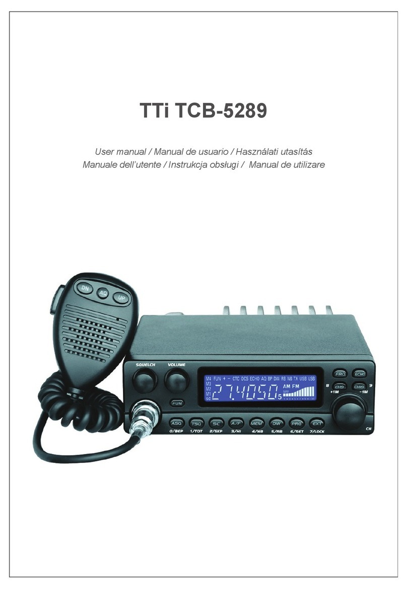
TTI TCB-1100 User manual

Owner’s Manual
AM/FM 40 CHANNEL & TONE SQUELCH
CITIZENS BAND TRANSCEIVER
Characteristics of C-Five
1. Improved audio sensitivity by adopting audio compressing and
decompressing circuit.( general radio : S/N 45dB C-Five : S/N 70 dB)
2. Minimizing external RF interference by using NB circuit.
3. Convenient change of digital touch SQ and Auto SQ.
4. Visual enjoyment of identifying transmitting sound by function of voice
dancing.
Downloaded from www.cbradio.nl

5. Identifying transmitting by red LED lighting and receiving by green LED
lighting.
6. Adopting wide negative color LCD.
7. Long life of display by use of bright LED.
8. Adding filter circuit on power line to remove engine noise interference.
9. Simple and impressive design.
10. Complete interfacing between CB radio users.
How to install your C-Five

Check the requirements for your vehicle before you begin installation.
Generally, you have a negative-ground system if the minus(-) battery terminal
is connected to the motor block. Contact your dealer in the event you are
unable to determine your vehicle’s polarity system.
Where to locate your CB radio.
Your new CB radio is designed to be installed under the dash or vertically on a
console of your vehicle.
Safety and convenience are the primary consideration in dealing exactly
where to locate your radio.
Caution : Be sure that the unit is located so that it does not interfere with the
driver, supplemental restraint systems (air bags) or impair access to any
controls. Connecting cables must be routed and secured in a manner as not to
interfere with the operation of the brake, accelerator or other controls.
Interference from either the unit or connecting cables may contribute to the

loss of control of the vehicle.
Power wiring (negative ground only)
Step 1 : If you have not determined whether your vehicle has a negative or
positive ground, do so now. Then disconnect the negative lead from the
battery to prevent short circuits theat can occur during wiring. Do not connect
this radio to positive ground electrical systems.
Step 2 : With negative ground
A. Connect the positive (RED WIRE) the one with in-line fuse holder to either
the (a) fuse block, (b) cigarette lighter, or (c) directly to the positive post on
your battery.
Usually, the fuse block is the most convenient connecting point. It is also
possible to connect to the Accessory terminal on the fuse block or ignition
switch, so that your CB automatically goes off when the ignition goes off.
B. Tightly connect the ground (BLACK WIRE) directly to the vehicle’s metal
frame. A good direct metal-to-metal ground is essential for optimum

performance.
Installations using the cigarette lighter socket for power require an extra
ground wire from the radio chassis to the vehicle if the radio is not fastened
to a grounded part of the vehicle.
Mechanical mounting.
Step 1 : Heeding the caution, use the mounting bracket as a template for
marking the location of screw holes under the dash. Use an awl, nail or other
sharp pointed object to mark the hole locations.
Step 2 : Drill a 3.2 mm diameter hole for each screw hole in the mounting
bracket. Attach the bracket to the dash with metal screws provided.
Extreme care should be exercised when drilling into the dash to avoid
damage to under-dash electronic ignition, cruise control, instrumental and/ or
accessory wiring.
Step 3 : Position the main unit between the bracket arms in line with the
retention knobs, Set the angle for optimum operating comfort and accessibility.

Step 4 : Tighten the retention knobs
External speaker
Fully insert the plug of external speaker into the jack (EX. SP) on the back of
the radio as below.
Antenna :

How to select, position, install and tune the right one for you.
Basically, you may choose from two types of mobile CB antennas-full-length
whip and loaded whip- and a variety of mounts (depending on where you locate your
antenna).
The dealer who sold you your CB radio can advise which type is best for you.
Where you locate your antenna does make a difference.
Some general rules for antenna location that can aid CB performance :
1. Put your mount as high on the vehicle as possible.
2. If possible, mount the antenna in the center of whatever surface you choose.
3. Keep antenna cables away from noise sources, such as the ignition system,
gauges, etc.
4. Make sure you have a solid metal-to-metal ground.
5. Exercise care to prevent cable damage.
Essentially, you have five location choices : the roof, gutter, rear deck, front cowl or

rear bumper. Where you decide to locate your antenna will determine the type of
antenna you install. Again consult your CB radio dealer for advice and guidance.
Antenna installation.
Follow the manufacturer’s installation instructions carefully.
Warning : Never operate your CB radio without attaching an antenna or with a
broken antenna cable. This will result in damage to transmitter circuitry.
Safety notice : The antenna used for this radio must be installed to provide a
separation distance of at least 20cm (8 in.) from all persons and must not be co-
located or operating in conjunction with any antenna or transmitter.
Tuning your antenna.
Some antennas are factory tuned. However, performance can usually be improved by
slightly lengthening or shortening the antenna using a Standing Wave Ratio (SWR)
meter. For the exact procedures to be used, refer to the antenna manufacturer’s
installation manual.
Factors affecting CB range
Essentially, they are the same influences that optimize or limit AM and FM broadcast

signals.
Terrain : Hills, valleys and building naturally interrupt and shorten CB signals. In short,
anything that is between you and the person you want to talk to can shorten your CB
range. You can expect to maintain maximum transmitting/receiving performance in
flat, open country.
Weather : You can expect that CB range will be reduced – perhaps drastically – in
times of atmospheric disturbance, such as in a thunderstorm or heavy snow.
Sunspots too are known to adversely affect CB performance.
Noise :
A common source of excessive noise is the ignition system. In many vehicles today
the electric fuel pump is another possible source of noise. If you suspect this is true,
turn off the ignition. With the CB in receive mode the noise is no longer present this is
a source of the noise. In some cases the noise can be reduced or eliminated by
making sure the CB radio chassis is grounded. This is in addition to the power cord.
In extreme cases, additional grounding of components may be necessary.

C-Five operating controls0
Front panel controls :
1, POWER :
Press the button and it is lock in, your radio power is on. Press it again and the
button is lock out. your radio is off.
2. BUSY/TX
Green LED indicator showing the unit is receiving and Red LED indicator showing
the unit is transmitting.
3. EMG button
Press and release it and your radio selects channel 9 instantly.
Press and release it again and your radio selects to last used channel.

4. Mike jack
Insert the plug from the mike into the mike jack (8 pin modular jack) until it locked
in.
5.6.Volume UP/DOWN button
Adjust sound volume level (0-20) by depressing upper button and lower button of
FUNC. Volume level will be displayed as numeric and graphic when you adjust
volume and fixed after 2 seconds or at the time of pressing PTT key of mike.
7.8. Channel UP/DOWN
Select Channel by depressing left button and right button of FUNC.
9. FUNC button
Control of SQ, T-SQ UP/DOWN, RGB ON/OFF, BEEP ON/OFF
SQ UP/SOWN
Press and release FUNC button one time and ‘SQ-L’ will blink.
Adjust SQ level (0-19) and SQ will be displayed as numeric and graphic when you
adjust SQ and fixed after 2 seconds or at the time of pressing PTT key of mike
T-SQ UP/DOWN

Press and release FUNC button two times and ‘T-SQ’ will blink. Select the channel
by depressing upper button and lower button of FUNC and the channel will be
memorized after 2 seconds or at the time of pressing PTT key of mike.
RGB
Press and release FUNC button three times and ‘RB’ will blink. And n select ‘on’
or ‘off’ with upper button or lower button which will be memorized after 2 seconds
or at the time of pressing PTT key of mike.
BEEP
Press and release FUNC button four times and ‘BP’ will blink. And select ‘on’ or
‘off’ with upper button or lower button which will be memorized after 2 seconds or
at the time of depressing PTT key of mike.
10. AM/FM button
Select AM or FM by press and release it.
11. T-SQ (tone squelch)
‘T-SQ’ will be displayed when you use the channel with T-SQ assigned.

T-SQ will be inoperative in AM mode.
12. A-SQ (automatic noise squelch)
Automatic squelch the noise when no signal in RX and ‘A-SQ’ will be
displayed.
13. SCAN
Press and release the SCAN button to activate SCAN mode and SCAN will
be displayed. And the radio will start checking the channels and stop and
stay at the channel where strong receive signal exist and start checking
again after 5 seconds. To turn scan off, press and release the SCAN button
again.
If you prefer to stay at the channel where the scan stop, just turn scan off.
If you press PTT on the channel where the scan stop, the scan will start
checking 3 seconds after PTT.
In the scan mode, press and release the upper button and the scan will
check the channels downward or press and release lower button and the
scan will check the channels upward.
14. DW
When you use some channel (main channel) and press and release DW button

and ‘DW’ will be displayed. And change the channel (changed channel : sub
channel). The radio check the sub channel and stay for 0.5 second every 5
seconds. Press PTT at one of both channels, PTTed channel become main
channel.
If no receive signal for 5 seconds after PTT, DW will start again.
15. ME/MR (M1, M2. M3)
Select the channel and press M1(M2, M3) for longer than 1 second. Then
‘M1’(M2, M3) will blink and the channel will be memorized.
1. ANT
Connect plug of the antenna cable (MJ type).

2. Power
12-24VDC
3. EX, SP
Connect external speaker plug (3,5 mm Dia).
1.FUNC 2. CH DOWN 3. CH UP 4. VR UP 5. VR DOWN : Same as above on
front panel of the unit.

6. EL-POWER (electronic switch)
Press and release it and the radio will be on/off only when the POWER lock in the
main unit.
7. PTT
Press PTT to transmit and release to receive.
8. MC/OSQ
Press and release continuously and the channel change to M1 to M2 to M3 to last
channel used. Press it longer and relase, it will operate as monitor button.
9. Mic unit
Hold the mike about 3-5 from your mouth and speak in a normal voice.
zMagnetic of mike back can hang on to the steel cabinet of the unit.
T-SQ table

CHANNEL FREQ,Hz CHANNEL FREQ,Hz REMARK
1 67.0 25 156.7
2 69.3 26 162.2
3 74.4 27 167.9
4 77.0 28 173.8
5 79.7 29 179.9
6 82.5 30 186.2
7 85.4 31 192.8
8 88.5 32 203.5
9 91.5 33 210.7
10 94.8 34 218.1
11 97.4 35 225.7
12 100.0 36 233.6
13 103.5 37 241.8
14 107.2 38 250.3
15 110.9 39 62.5
16 114.8 40 64.7
17 118.8 41 71.9
18 123.0 42 159.8
19 127.3 43 183.5
20 131.8 44 189.9
21 136.5 45 196.6
22 141.3 46 199.5
23 146.2 47 206.5
24 151.4 48 229.1

ELECTRICAL SPECFICATION
1. General features.

SYSTEM CPU CONTROL SYSTEM (FREQUENCY COMBINATION)
C H A N N E L AM 40CH + FM 40CH(80 CHANNEL) - option 240channel
MOD ULAT ION AM / FM
CHANNEL
SPACE
10KHz
S U B T O N E CTCSS CHANNEL
SPEAKER 8Ω 3W
M I K E DYNAMIC MIKE
OPERATING
TEMPERATURE
-10℃ - +55℃
S I Z E 150(W) x 140(D) x 40(H)
NET WEIGHT 0.86Kg
2, TRANSMISSION
AERIAL
IMPEDIANCE
50Ω(IMPERDIANCE)
P O W E R 3watt ±10%
MAX,
FREQUENCY
DEVIATION
±2.0KHz ±10%
D I S T O R T I O N LESS THAN 3%
S/N RATIO MORE THAN 50㏈
HARMONIC
SUPPRESSION
MORE THAN 60dB
FREQUENCY
STABILITY
±600Hz(0.005%)
POWER
CONSUMPTION
AM : 1500㎃, FM: 1000㎃
3. RECEIVE

DEMODULATION DOUBLE SUPER HETERODINE
S E N S I T I V I T Y AM-0.5㎶(10㏈ S/N), FM-0.2㎶(S/N 12㏈)
AUDIO
SENSITIVITY
0.2㎶ - 1㎶
SELECTIVITY MORE THAN 65㏈
AUDIO OUTPUT
POWER
MORE THAN 3 watt
DISTORTION LESS THAN 6.0%
POWER
CONSUMPTION
250㎃(STANDBY), 600㎃(MAX)
S/N RATIO MORE THAN 65㏈
END
Other manuals for TCB-1100
1
Table of contents
Other TTI Radio manuals
