FG-STAD Installation Notice EN_v1.1.1_052021
Specific parameters of protection
mode in question
5
TTK Headquarters /19 Rue du Général Foy, 75008 Paris /France /T: +33 1.56.76.90.10 /F: +33 1.55.90.62.15 /www.ttk.fr /[email protected] TTK Oil & Gas Division /19 Rue du Général Foy / 75008 Paris / France /T: +33 1.30.51.79.84 /F : +33 1.55.90.62.15 /www.ttk.fr /[email protected] TTK UK Ltd. /3 Luke Street London EC2A 4PX /United Kingdom /T: +44 20 7729 6002 /F : +44 20 7729 6003 /www.ttkuk.com /[email protected]om TTK Pte Ltd. /#09-05, Shenton House, 3 Shenton Way /Singapore 068805 /T: +65 6220.2068 /M: +65 9271.6191 /F: +65 6220.2026 /www.ttk.sg /[email protected] TTK Asia Ltd. /2107-2108 Kai Tak Commercial Building /317 Des Voeux Road Central /Hong Kong /T: +852 2858.7128 / F: +852 2858.8428 /www.ttkasia.com /[email protected] TTK Middle East FZCO /Building 6EA, Office 510 PO Box 54925 /Dubai Airport Free Zone /UAE /T: +971 4 70 17 553 /M: +971 50 259 66 29 /www.ttkuk.com /[email protected] Thomas Sales & Marketing Inc. TTK Master Distributor For USA /7200 W 66th St /Bedford Park, IL 60638 /USA /T: +1 630-518-4724 /www.ttkusa.com /[email protected] b. Sensor terminal connections
Although carefully prepared to ensure technical accuracy, this brochure is intended for promotional use only. TTK cannot guarantee that the information contained herein is free of errors or omissions, and hence does not accept liability
related to the use of its equipment. TTK maintains its obligations set out in the Standard Terms and Conditions of Sale and will not, under any circumstances, assume liability for any incidental damages, indirect or consequential, arising
from the sale, resale, use or misuse of this product. All purchasers accept their responsibility as sole judge of the suitability of the product for the intended use.
FG-NET, FG-SYS and TOPSurveillance are trademarks of TTK S.A.S. © TTK 2021
TTK’s FG-OD cables are certified ATEX / IECEx according to the marking mentioned above, according to EN / IEC 60079-0, EN / IEC 60079-18 and EN / IEC 80079-34.
Special installation precautions are required when working in explosive atmospheres, such as use of zener barriers, specific location of alarm and/or satellite panels etc.
The client is responsible for verifying that the design and installation of the detection system, in an ATEX / IECEx classified zone, is consistent with the classification of the area.
The client retains sole responsibility for its use of TTK’s products.
Meaning of marking
4
Figure 3: Dual output wiring must have a common ground
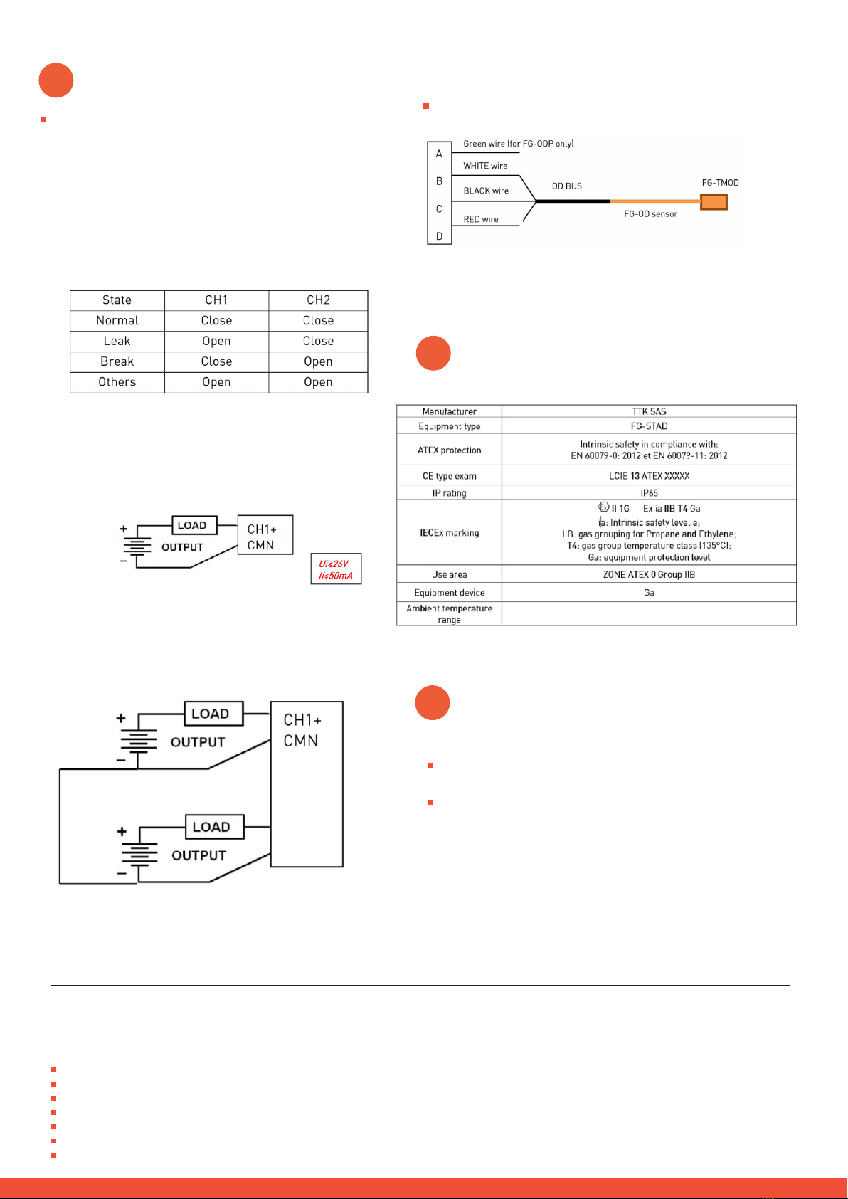
Figure 4: Sensor input wiring
Switch terminal parameters:
Ui: 26V, Ii: 50mA, Pi: 0.325W, Ci: NA, Li: NA
Sensor terminal parameters:
Uo: 3.6V, Io: 20mA, P0: 0.018mW, Co: 15µF, Lo/Ro: 200m
a. Discrete output.
Note: It is very important to follow the output circuit polarity as
shown below, with the positive (+) side of the circuit wired to the
CH1+/CH2+ terminal and the negative side (-) wired to the CMN
terminal. Otherwise, the output circuit will remain ACTIVE (or
CLOSED) regardless of the state of the output channel.
The discrete output of FG-STAD is driven by the unit and
designed to give an alarm signal.
Other faults: Leak and break sensor / bus simultaneous,
power supply lost.
Table 1: True discrete output table
Figure 2: Single-output wiring
Mounting (continued)
3
-22°F<=Ta<=175°F-22°F<=Ta<=175°F
CH2+
CMN


