TTulpe CO Comfort Wi-Fi Series User manual


1
BEFORE THE FIRST USING YOUR ELECTRIC STORAGE WATER
HEATER, CAREFULLY READ THIS OPERATION MANUAL
DEAR CUSTOMER!
Congratulations on your purchase of an electric water heater TTULPE.
Water heaters TTULPE are designed and manufactured in strict accordance with
domestic and international standards guaranteeing operation reliability and safety.
Present manual applies to TTULPE models of CO Comfort Wi-FI. The full name
of the model of your heater is specified in "Manufaturer’s warranty" section (sub-sec-
tion "Note of sale") and in the marking plate on the heater casing.
1. APPLICATION
Electric water heater (hereinafter referred to as the EWH) is designed to provide
with hot water for domestic and industrial facilities having a cold water supply line
pressure of not less than 0.05 MPa and not more than 0.7 MPa.
EWH shall be operated indoors in heated spaces and it is not designed for operation
in continuous flow mode.
2. SCOPE OF SUPPLY
Water heater
- 1 pcs.
Safety valve of GP type
- 1 pcs.
Operation manual
- 1 pcs.
Anchors for fastening (option)
- 1 set
Packaging
- 1 pcs.
3. MAIN TECHNICAL CHARACTERISTICS
EWH power supply shall be within the range of 230 V ± 10%. Supply network
frequency 50 Hz ± 1%. Volume of the inner tank and heating element power are speci-
fied in the marking plate on the casing. Thread diameter in water inlet and outlet pipes
- G1/2 ".
The manufacturer reserves the right to make changes to the design, complete set
and specifications of the heater without prior notice.
ы
EN

2
Table 1
Model
EWH useful
volume, l
Average heating
time T = 45° C at 2
kW
Installation
CO30VW Comfort Wi-Fi
25
0 h 39 min.
vertical
CO50VW Comfort Wi-Fi
42
1 h 06 min.
vertical
CO80VW Comfort Wi-Fi
67
1 h 45 min.
vertical
CO50HW Comfort Wi-Fi
42
1 h 06 min.
horizontal
CO80HW Comfort Wi-Fi
67
1 h 45 min.
horizontal
4. DESCRIPTION AND PRINCIPLE OF OPERATION
The outside casing of the EWH is made of impact-resistant plastic. Inner tanks have
a special bio-glass-porcelain coating reliably protecting the inner surface against chem-
ical corrosion. The space between the outside casing and the inner tank is filled with
polyurethane foam - a modern, ecologically clean thermal insulation, which has the best
heat-saving characteristics. CO Comfort Wi-FI models have two screwed nozzles: for
inlet of cold water (Fig. 1, p. 3) with a blue ring and for outlet of hot water (Fig. 1, p. 2)
—with a red ring, and equipped with an additional drain connection (closed with metal
plug button) for draining the water and flushing the inner tank (Fig. 1, p. 17). The control
panel, in all models, is on the front side of the EWH. (Fig. 1, p. 16).
Tubular heating element (THE), thermostat and thermal switch sensors are
mounted on the removable flange. THE is used to heat water and thermostat provides
with possibility of heating temperature regulation up to +65°С. All models have elec-
tronic control with sensor adjustment. Electronics maintain automatically water tem-
perature at the level set by the user. The thermostat is used for protecting against
EWH overheating, which disconnects THE from power supply when water tempera-
ture exceeds 95°С. (Fig. 3).
Safety valve (Fig. 1, p. 5) operates as the check valve, ensuring protection of the
water ingress from the water heater into the sewage system in case of pressure drop in
the sewage system and in case of pressure rise in the tank at high water heating, as
well as the functions of the safety valve, releasing overpressure in the tank at high wa-
ter heating. During water heater operation water may leak out of the exhaust outlet
pipe of the safety valve to relieve excessive pressure, which is made for the purpose of
water heater safety. This outlet pipe shall remain open to the atmosphere and be in-
stalled constantly down.
Drainage of water from the safety valve exhaust pipe into the drain shall be pro-
vided with installation of the corresponding EWH drainage.
ы
EN

3
It is required regularly (at least once a month) to discharge a small amount of water
through the exhaust pipe of the safety valve into the drain to remove lime deposits and
to test the operating functionality of the valve. Handle (Fig. 1, p. 15) is intended to open
the valve. It is necessary to control when operating water heater this handle to be in
position closing water draining from the tank.
5. SPECIFYING SECURITY MEASURES
Electrical safety and corrosion protection of EWH are guaranteed only if there is an
effective grounding in accordance with applicable electric installation rules and regula-
tions.
Plumbing pipes and fittings shall conform to parameters of water main and have
the required certificates of quality.
When installing and operating EWH the following is not allowed:
•To power EWH if EWH is not filled with water.
•To remove the protective cover when the power is on.
•Use EWH without grounding or use water pipes as grounding.
•To connect EWH to water supply with pressure exceeding 0.7 MPa.
•To connect EWH to the water supply without safety valve.
•To drain water from EWH with power switched on.
•To use spare parts not recommended by the manufacturer.
•To use water from the EWH for cooking.
•To use water containing impurities (sand, small stones), which might lead to
EWH and safety valve breakdown.
•To modify design and installation dimensions of EWH brackets.
Ambient temperature shall be within the range of 5ºС to 40ºС. Water in freezing
EWH at negative temperatures results in malfunction, which is not a warranty case.
Attention should be paid to children so that they do not play with EWH.
EWH is not intended for use by persons (including children) with limited
physical, sensory or mental capabilities, or by persons who do not know
how to use the EWH, except for cases when this happens under the
supervision or instructions by persons responsible for safety of the EWH.
During EWH operation, it shall be inspected regularly for proper health (absence
of dripping, burning smell, wiring sparks, etc.). In the case of long interruptions in water
heater operation, water supply failures, EWH shall be disabled and cold water inlet
valve shall be shut off.
ы
EN

4
6. INSTALLATION AND CONNECTION
All installation, plumbing and electrical works shall be performed by qualified per-
sonnel.
7. ARRANGEMENT AND INSTALLATION
All installation, plumbing and electrical works shall be performed by qualified per-
sonnel.
EWH installation shall be performed in accordance with marking on the housing.
It is recommended to install EWH as close as possible to the place of hot water
using to reduce heat loss in the pipes.
When choosing the place of installation it should be taken into account the total
weight of EWH filled with water. Walls and floor with low carrying capacity should be
strengthened accordingly. When drilling (making) holes in the wall consider cables,
ducts and pipes in the wall.
EWH is suspended by brackets on hook anchors fixed in the wall. Hooks mounting
on the wall shall exclude spontaneous movement of EWH brackets along them.
The manufacturer bears no liability for EWH falling associated with improper in-
stallation of anchors and their selection.
For EWH maintenance the distance from the protective cover to the nearest surface
in the direction of the removable flange axis shall be at least 30 cm for all models.
In order to avoid damage of the user’s and/or third parties’ property in
the event of a faulty hot water system, it is required to install EWH in
spaces with waterproofing and drainage to the sewers, and in no case to
place under items exposed to the water under EWH. When placed in un-
protected areas a protective plate (not supplied) with drainage into sewers
shall be installed under the EWH.
In case of placing EWH in hard-to-reach places in order to perform maintenance
and warranty service (mezzanine floors, niches, ceiling voids, etc.), installation and dis-
mantling of EWH is carried out by the user on his own or for his own account.
Note: safety tray is not included into the scope of EWH supply.
8. CONNECTION TO WATER MAINS
Cold water shall be supplied to EWH using pre-filter with water treatment level not
less than 200 µm.
ы
EN

5
Install pressure relief valve (Fig. 1, p.5) at the cold water inlet (Fig. 1, p. 3) tube
with the blue ring, by 3.5-4 turnings, ensuring junction tightness with any sealing ma-
terial (flax, FUM tape, etc.).
During EWH operation you can observe water leak out of the outlet pipe of the
safety valve for excessive pressure release to ensure safety of the water heater. It is
recommended to connect to a drainage hole a rubber or silicone pipe of the relevant
diameter for moisture removal.
Connection to the water supply line shall be carried out in accordance with Fig. 1
using copper, plastic pipes or special flexible sanitary wiring. Do not use any used flex-
ible wiring. It is recommended to supply water to EWH through filter installed on the
cold water main (not included in the scope of supply).
Do not use used flexible feed pipes. Do not operate the EWH without
safety valve or with valve made by other manufacturers.
Figure 1. EWH connection diagram to water supply
ы
EN

6
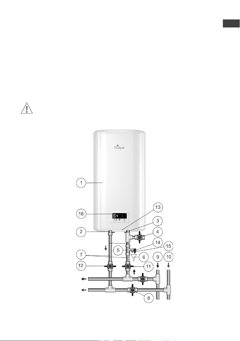
Figure 1: 1 –EWH, 2 –hot water pipe, 3 –cold water pipe, 4 –drain valve
(not in the scope of supply), 5 –safety valve, 6 –drainage (not in the scope of
supply), 7 –feed pipe, 8 –shut off valve when EWH operation, 9 –cold water main, 10
–hot water main, 11 –cold water shut-off valve, 12 –hot water shut-off valve, 13 –
protective cover, 14 –exhaust pipe of the safety valve, 15 –handle for opening pressure
relief valve, 16 –control panel.
After connecting EWH make sure that cold water shut-off valve is open and hot
water shut-off valve (Fig. 1, p. 8) is closed. Open cold water tap in EWH (Fig. 1, p. 11),
hot water outlet valve (Fig. 1, p. 12) and hot water tap on mixer to ensure outflow of air
from the EWH. When the final EWH filling, water will continuously flow out of mixer
tap. When connecting EWH in places not provided with water supply it is permitted to
supply water in EWH from auxiliary tank using pumping station, or from reservoir
placed at a height of not less than 5 meters over the top of EWH.
Note: for ease of maintenance during EWH operation it is recommended to install
drain valve (Fig. 1, p.4) in accordance with Fig. 1 (for models not equipped with drain-
age pipe. (not in the scope of EWH supply)).
If the water pressure exceeds 0.7 MPa, at EWH cold water inlet, before the safety
valve (in the direction of water flow), the appropriate pressure reducing valve (not sup-
plied with the EWH) shall be installed to reduce water pressure to standard.
9. CONNECTION TO POWER SUPPLY
Prior to the water heater connection to electrical network, make sure its parameters
complies with the technical specifications of the water heater.
ATTENTION! Prior to power activation make sure EWH is filled with water!
Water heater shall be earthed to ensure safe operation. EWH is equipped with the
stationary power cable (option) with Europlug (option). Power outlet shall have an earth
terminal with the connected earthing wire and located in the area protected from mois-
ture, or comply with the requirements not less than 1РХ4.
ы
EN

7
10. OPERATION
Figure 2. Electronic control board
Figure 2: 1 –LCD display, 2 –button «▲» Temperature control / increasing the
heating temperature, 3 –button «▼» Temperature control / decreasing the heating tem-
perature, 4 –button «on/off» / switch on/switch off, 5 – button «Heating mode» / setting
the heating power, 6 –“No Frost” mode indication, 7 –indication «Economy» / mini-
mum power, 8 –indication «Optimal» / conventional power, 9 – indication «Turbo» /
maximum power, 10 –Wi-Fi feature.
Switching on/switching off of the EWH is performed by pressing the central button
«on/off» (Fig. 2, p. 4), while the display shows the preselected heating temperature.
After 2.5 seconds, the display shows the current water temperature in the EWH. Selec-
tion of the heating power is performed by pressing the button «Heating mode» (Figure
2, p. 5), on the control panel. Mode 2 kW is accompanied by the indication of a control
lamp «Turbo» (Fig. 2, p. 9), 1,3 kW is accompanied by the indication of a control lamp
«Optimal» (Fig. 2, p. 8), and 0,7 kW is accompanied by the indication of a control lamp
«Economy» (Fig. 2, p. 7). Antifreeze mode is accompanied by the indication of a control
lamp «No Frost»(Fig. 2, p.6).
During the operation of the EWH, the user can adjust the temperature of the water
heating using two buttons «▲» «▼» Temperature control (Fig. 2, p. 2 and p. 3).
If you do not use the EWH in the winter time and there is a possibility of freezing
of the main waterways and the water heater itself, it is recommended to turn off the
power and drain the water from the EWH in order to avoid damage to the inner tank.
For control from a mobile device water heater has Wi-Fi function.
1. Install app "Tuya Smart" from GooglePlay or AppStore. Create an account.
2. Go to the section "Large Home Appliances"
3. Select "Boiler (Wi-Fi)"
4. Connection is made when the appliance is switched off (in the standby
ы
EN

8
mode).
5. Press and hold UP △and DOWN ▽buttons simultaneously until the
wireless connection icon starts to flash on and off on the display
6. Right after this touch "Add an appliance" button in Tuya Smart app
7. In application “Tuya Smart”:
• next follow the instructions of application.
Failures:
• make sure Wi-Fi function is enabled on your mobile device
• make sure you are connected to the Internet network 2.4 GHz
If there are any failures of wireless control through Wi-Fi, make sure that the Wi-
Fi network is functioning, the Internet connection is available and Tuya Smart app
works correctly. Please contact your Internet provider to fix the Wi-Fi network failures
and contact the app developer to remedy the app operation bugs if any.
11. TECHNICAL MAINTENANCE
When performing maintenance scale on THE is checked. At the same time residue
that may accumulate in the bottom of the EWH is removed. If there is scale on THE, it
can be removed by using scale removing means or mechanically. It is recommended to
hold the first technical maintenance after a year from the time of connection by experts
of a specialized organization and depending on intensity of scale and residue to deter-
mine intervals of follow-up maintenance. This action will extend the maximum EWH
service life.
The first replacement of the magnesium anode shall be made no later than 12
months from the date of EWH installation. In case of no mark of installation in warranty
certificate with the seal of installation company, the period is calculated from the date
of purchase. Regular periodic maintenance and annual replacement of the magnesium
anode in time is imperative to maintain the manufacturer's warranty. Replacement of
the anode must be accompanied by a mark in the warranty card in case of replacement
by a service organization, or an attached sales receipt for its purchase in case of replace-
ment by the owner.
ATTENTION: accumulation of scale on TEH may cause its damage .
Note: Damages to THE due to scale formation are not subject to warranty. Regular
maintenance is not included in the warranty of the manufacturer and the seller.
The following shall be carried out for maintenance:
•Turn off EWH power;
•Cool hot water or discharge it through the mixer;
ы
EN

9
•Cut off supply of cold water into EWH;
•Unscrew the relief valve or open drain valve;
•To put on the cold water supply inlet or discharge valve a rubber hose,
sending the other end down the drain;
•Open hot water tap on mixer and drain water from the EWH through
the hose;
•Remove the protective cover, disconnect wires, unscrew and remove
from the casing the removable flange;
•Clean if necessary THEs from scale and remove residue from the tank;
•Assemble, fill the EWH with water and power on.
In models with drain pipe, it is enough to cut off the flow of cold water into the
EWH, unscrew the drain stub on drain pipe and open hot water tap. Once the water is
discharged, you can open for a while cold water supply in EWH for additional tank
washing.
When conducting EWH maintenance by forces of specialized organization mark
with the seal of organization performing maintenance shall be made in service coupon.
12. POSSIBLE FAULTS AND REMEDIES.
Malfunction
Possible cause
How to fix
Hot water pressure from
EWH decreased. Cold
water pressure keeps at
the level.
Clogged inlet safety
valve
Remove the valve and clean it in
water
Heating time increased
THE is covered with a
layer of sludge
Remove the flange and clean the
THE
Supply voltage decreased
Contact power main operation ser-
vice
Frequent tripping of
thermal switch
The set temperature is
close to the limit
Set lower value of water heating
temperature
Thermostat tube is cov-
ered with sludge
Take out the EWH the remova-
ble flange and gently clean the
tube from scale
EWH operates but is not
heating water
Valve (Fig. 1, p.8)
is not closed or out of or-
der
Close or replace the valve (Fig. 1,
p. 8)
ы
EN

10
Powered EWH does not
heat water. No backlights
of indicator lamps.
1) no voltage in electric
network;
2) damaged power cord.
3) Thermal switch actu-
ated and not switched on
1) Check voltage at the electrical
outlet;
2) Contact a qualified service cen-
ter.
3) Disconnect from the power
supply, remove EWH protective
cover, press the button on thermal
switch until you hear a click (fig.
2) install the cover and turn on
the power
These faults are not defects of EWH and shall be fixed by the consumer or by a
specialized organization at his own expense.
In case of failure to fix problems using the above recommendations or in case of
others problems revealing you should contact the authorized service center listed in the
operation manual.
Figure 2. Thermal switch arrangement diagram
13. TRANSPORTATION AND STORAGE OF ELECTRIC WATER HEATERS
Transportation and storage of electric water heaters shall be carried out in accord-
ance with manipulation marks on the packaging:
need to protect the goods from moisture
fragile, delicate handling
-recommended storage temperature range from +5° to +40° С
correct vertical position of cargo;
Push
ы
EN

11
14. DISPOSAL
When complying with the rules of EWH installation, operation and maintenance
and when water quality complying with current standard the manufacturer sets EWH
lifespan of 9 years from the date of purchase.
All parts of the heater are made of materials allowing, where appropriate, environ-
mentally sound disposal which must be made in accordance with the rules and regula-
tions of the country where the water heater is operated.
When disposing of the EWH comply with local environmental laws and guidelines.
The manufacturer reserves the right to make changes to the design and specifica-
tions of the heater without prior notice.
15. MANUFACTURER'S WARRANTY
The manufacturer sets 2 years as the period of warranty for water heater, and war-
ranty period for parts and components is as follows:
- for water containing tank (inner tank) - 5 years;
- for other components (heating element, thermostat, indicator lights, gaskets, tem-
perature indicator, pressure relief valve) - 2 years.
The warranty period is calculated from the date of EWH sale. If there is no or cor-
rected date of sale and shop stamp, the warranty period is calculated from the date of
EWH manufacture. Claims within the warranty period are accepted only on presentation
of the warranty card with marks of the seller, and the identification plate on the casing
of the EWH. Release date of a water heater is encoded in a unique serial number, located
on the identification plate on the casing. EWH serial number consists of thirteen digits.
The third and fourth digits of the serial number are year of manufacture, the fifth and
sixth digits - month of release, the seventh and eighth digits - day of EWH release.
Claims within the warranty period are accepted only on presentation of the guarantee
card with marks of the seller, and the identification plate on the casing of the EWH.
The warranty shall apply to EWH only. Responsibility for compliance with princi-
ples of installation and connection shall be borne by the buyer (in case of connection by
his own) or by the installer carrying out connection.
The first replacement of the magnesium anode shall be made no later than 12
months from the date of EWH installation. In case of no mark of installation in warranty
certificate with the seal of installation company, the period is calculated from the date
of purchase. Regular periodic maintenance and annual replacement of the magnesium
anode in time is imperative to maintain the manufacturer's warranty. Replacement of
the anode must be accompanied by a mark in the warranty card in case of replacement
by a service organization, or an attached sales receipt for its purchase in case of replace-
ment by the owner.
ы
EN

12
The manufacturer shall not be liable for defects due to violations of principles of
installation, operation and maintenance of EWH set forth herein, including in cases
where these defects have arisen due to invalid parameters of mains (electricity and wa-
ter), where EWH is operated, and due to the intervention of a third party. Manufacturer’s
warranty does not cover claims for appearance of EWH.
16. INFORMATION ON THE MANUFACTURER
Manufacturer:
THERMEX heating Technology (Jiangmen) CO., Ltd
No. 51, Jianshedonglu , Taoyuan town, Heshan City, Guangdong Province, China
ZIP: 529725
All models have been certified and comply with requirements of European Directives.
NOTE OF SALE
Model _________________________ Serial No. ___________________________
Date of sale __________________________________, 20 ______ .
Dealer: __________________________________________________
Dealer's representative
signature ____________________________
The product is completed; I have no claims for the appearance of the product.
Operation manual with the necessary marks is received. I have read, understood and
accepted operation rules and warranty terms.
Customer's signature: ____________________
Dealer's seal
ы
EN

13
PRIMA DEL PRIMO USO DELLO SCALDACQUA LEGGERE ATTEN-
TIVAMENTE IL PRESENTE MANUALE D’USO
GENTILE CLIENTE!
Ci congratuliamo con Lei per l’acquisto dello scaldacqua elettrico TTULPE!
Gli scaldacqua TTULPE sono progettati e prodotti nello stretto rispetto degli stand-
ard internazionali che garantiscono l’efficienza e la sicurezza dell’uso.
Il presente manuale è valido per i modelli TTULPE di serie SH Shadow Wi-Fi. Il
titolo completo del modello dello scaldacqua da Lei acquistato è indicato nella sezione
del manuale «Contrassegno confermante la vendita» e sulla targhetta d’identità sul
corpo dell’apparecchio.
1. APPLICAZIONE
Lo scaldacqua elettrico (qui di seguito «Lo scaldacqua») è la soluzione per fornitura
dell’acqua calda nei locali ad uso abitativo e quelli industriali dotati della tubazione di
acqua fredda con la pressione minima di 0,05 MPa e la pressione maxima di 0,7 MPa.
La manutenzione dello scaldacqua avvenga negli ambienti chiusi e ben riscaldati,
lo scaldacqua non è adatto al lavoro con il flusso di acqua continuo (quale scaldacqua
istantanei).
2. KIT di fornitura
Scaldacqua elettrico
- 1 pz.
Valvola di sicurezza tipo GP
- 1 pz.
Manuale d’uso
- 1 pz.
KIT di ancoraggi di fissaggio
(opzionale)
- 1 KIT
Imballaggio
- 1 pz.
3. PRINCIPALI CARATTERISTICHE TECNICHE
La tensione fornita allo scaldacqua deve corrispondere al valore pari a 230V ±10%.
La frequenza della rete di alimentazione elettrica deve essere di 50Hz ± 1 %. La ca-
pacità del serbatoio interno e la potenza della resistenza elettrica sono indicati sulla tar-
ghetta d’identità sul corpo dell’apparecchio. Il diametro della filettatura dei raccordi
d’entrata e di uscita è G1/2".
ы
IT

14
Il produttore si riserva il diritto di riportare le variazioni nella dotazione, struttura e
caratteristiche dello scaldacqua senza obbligo di preavviso.
Tabella 1
Modello
Gamma
Capacità
utile dello
scaldacqua,
l
Tempo medio di
riscaldamento,
ΔТ°=45°С con la
potenza di 2 kW
Posizionamento
CO30VW Comfort Wi-Fi
30
25
0 ore 39 minuti
verticale
CO50VW Comfort Wi-Fi
50
42
1 ore 06 minuti
vertical
CO80VW Comfort Wi-Fi
80
67
1 ore 45 minuti
vertical
CO50HW Comfort Wi-Fi
50
42
1 ore 06 minuti
orizzontale
CO80HW Comfort Wi-Fi
80
67
1 ore 45 minuti
orizzontale
4. DESCRIZIONE E PRINCIPIO DI FUNZIONAMENTO DELLO
SCALDACQUA
Il corpo esterno dello scaldacqua è realizzato del materiale plastico resistente agli
urti. I serbatoi interni hanno il rivestimento speciale in biovetroporcellana che protegge
a modo sicuro la superfecie interna della corrosione elettrochimica. Lo spazio tra il
corpo esterno ed il serbatoio interno è riempito con poliuretano schiumato che presente
un’isolamento termico moderno ed ecologico con le ottime caratteristiche d’isolamento
termico. I modelli SH Shadow Wi-Fi sono dotati dei due raccordi filettati: per l’entrata
dell’acqua fredda (Fig. 1, pos. 3) con l’annello di colore blu e per l’uscita dell’acqua
calda (Fig. 1, pos. 2) –con l’annello di colore rosso, ed anche sono dotati del raccordo
di scarico supplementare (chiuso con un tappo metallico) per lo scarico dell’acqua e
lavaggio dello serbatoio interno (Fig. 1, pos.17). Sulla facciata dello scaldacqua di tutti
i modelli è posizionato un pannello di comando (Fig. 1, pos.16).
Sulle flange rimovibili sono montati i riscaldatori tubolari (resistenze elettriche) ed
i sensori del termostato ed interruttore termico. La resistenza elettrica serve al
riscaldamento d’acqua ed è controllata dal termostato che assicura la possibilità di rego-
lazione graduale di temperatura di riscaldamento fino a +65°С. Tutti i modelli sono
dotati del controllo elettronico con la tastiera a sfioramento. I componenti elettronici in
modo automatico mantengono la temperatura dell’acqua al livello prescelto dall’utente.
L’interruttore termico serve per proteggere lo scaldacqua del riscaldamento anormale
d’acqua e provoca l’apertura del circuito di alimentazione alla resistenza elettrica in
caso di riscaldamento d’acqua più di +95°С (Fig. 3).
La valvola di sicurezza (Fig. 1, pos.5) fa la funzione della valvola di ritegno che
impedisce il ritorno dell’acqua dallo scaldacqua alla tubazione in caso del calo di pres-
sione nella tubazione stessa ed anche in caso di salita di pressione in serbatoio durante
il riscaldamento forte dell’acqua ed anche fa la funzione della valvola di protezione che
evita sovrappressioni al serbatoio durante il riscaldamento forte dell’acqua. Durante il
funzionamento dello scaldacqua l’acqua può gocciolare dall’attacco di scarico della val-
vola di sicurezza per lo scarico della pressione eccessiva che provvede la sicurezza dello
ы
IT

15
scaldacqua. Questo attacco di scarico deve essere lasciato aperto all'atmosfera e deve
essere previsto in pendenza continua verso il basso.
E indispensabile assicurare lo scarico d’acqua dall’attacco di scarico della valvola
di sicurezza (Fig. 1, pos. 14) alla canalizzazione mediante l’apposito scarico (Fig. 1,
pos. 6) previsto durante il montaggio.
E indispensabile provvedere regolarmente (minimo una volta al mese) allo
scarico di una porzione piccola dell’acqua dall’attacco di scarico della valvola di
sicurezza alla canalizzazione per lo scopo di pulizia del calcare e controllo di
funzionalità della valvola di sicurezza. Una leva (Fig. 1, pos. 15) serve per aprire la
valvola di sicurezza.Occorre assicurare che durante il funzionamento dello scaldacqua
la leva suindicata sia in posizione che chiuda lo scarico dell’acqua dal serbatoio.
5. INDICAZIONI DI SICUREZZA
La sicurezza elettrica dello scaldacqua è garantita solo in presenza della messa a
terra efficace realizzata in conformità alle vigenti normative di montaggio elettrico.
L’alimentazione idrica e valvolame di ritenuta devono essere conformi ai req-
uisiti della tubazione ed avere tutti i certificati di qualità obbligatori.
Non è ammissibile durante il montaggio e manutenzione dello scaldacqua:
effettuare il collegamento elettrico dello scaldacqua non completamente pieno
d’acqua;
togliere la calotta di protezione con l’alimentazione elettrica accesa;
usare lo scaldacqua senza messa a terra oppure utilizzare quale messa a terra i
tubi idrici;
connettere lo scaldacqua alla tubazione con la pressione superiore a 0,7 MPa;
connettere lo scaldacqua alla tubazione in assenza della valvola di sicurezza;
scaricare l’acqua dallo scaldacqua con l’alimentazione elettrica accesa;
utilizzare ricambi non raccomandati dal Produttore;
utilizzare l’acqua dallo scaldacqua per cucinare;
utilizzare l’acqua contenente i pezzetti meccanici (sabbia, pietre piccole), che
possono provocare il malfunzionamento dello scaldacqua e della valvola di
sicurezza.
cambiare la struttura e misure di montaggio delle staffa di sospensione dello
scaldacqua.
La temperatura dell’ambiente in cui funziona lo scaldacqua deve essere compresa
tra i limiti da 5ºС fino a 40ºС. Il congelamento dell’acqua nell’apparecchio in caso delle
temperature sotto zero risulta nella sua rottura che non presenta il caso di garanzia.
Occorre prestare l’attenzione dei bambini e prevenire i suoi giochi con lo
scaldacqua. Lo scaldacqua non è addatto a manutenzione eseguita dalle
persone (incluso bambini) con le abilità fisiche, tattili e mentali limitate ed
anche dalle persone non istruite sull’utilizzo dello scaldacqua all’eccezione
ы
IT

16
dei casi in cui l’utilizzo si effetua sotto la sorveglianza oppure secondo le
istruzioni delle persone responsabili della sicurezza dello scaldacqua.
Durante l’utilizzo dello scaldacqua occorre regolarmente fare delle verifiche del
suo corretto funzionamento (assenza di perdite d’acqua, odore di bruciato, scin-
tillamento del cablaggio, etc.). In caso della sospensione prolungata dell’uso dello
scaldacqua, interruzione del funzionamento dell’alimentazione idrica o elettrica occorre
scollegare lo scaldacqua dalla rete elettrica e chiudere il rubinetto dell’alimentazione di
acqua fredda.
6. INSTALLAZIONE E COLLEGAMENTO
Tutti il lavori di montaggio, idraulici ed elettrici verranno eseguiti solo dal
personale qualificato.
7. POSIZIONAMENTO ED INSTALLAZIONE
Tutti il lavori di montaggio, lavori idraulici ed elettrici verranno eseguiti solo dal
personale qualificato.
L’installazione dello scaldacqua deve essere effettuata secondo la marchiatura sul
corpo e secondo i dati dalla Tabella 1.
Si consiglia di collocare lo scaldacqua in massima prossimità dal punto di prelievo
di acqua calda per evitare dispersioni di calore lungo le tubazioni.
Occorre considerare il peso totale dello scaldacqua con completo riempimento d’ac-
qua nel processo di scelta di posto di fissaggio. Il muro ed il pavimento di scarsa robust-
ezza richiedono rinforzamento. Ci vuole considerare l’eventuale presenza dei cavi
elettrici, condotti e tubi nel processo di perforazione (esecuzione dei fori) del muro.
Lo scaldacqua viene appeso agganciando la staffa di sospensione del corpo agli
ancoraggi, fissati in precedenza al muro. Il montaggio degli ancoraggi al muro deve
escludere lo spostamento spontaneo delle staffa di sospensione dello scaldacqua lungo
gli ancoraggi stessi.
Il Produttore non è responsabile dell’eventuale caduta dello scaldacqua in seguito
al fissaggio scorretto degli ancoraggi e alla scelta sbagliata degli ultimi.
Per la manutenzione dello scaldacqua la distanza dalla calotta di protezione alla
superficie più vicina in direzione dell’asse della flangia rimovibile deve essere minimo
30 centimetri per tutti i modelli.
ы
IT

17
AVVERTENZA! Per evitare il danno alla proprietà dell’utente e (o) delle
persone terzi in caso di malfunzionamento dello sistema di fornitura
dell’acqua calda occore installare lo scaldacqua nei locali con pavimenti
impermeabili e dotati dello scarico alla canalizzazione, in nessun caso non
è consentito il collocamento sotto lo scaldacqua degli oggetti che possono
essere danneggiati dall’acqua. In caso d’installazione nei locali non pro-
tetti occorre montare sotto lo scaldacqua una vasca di protezione con lo
scarico nella canalizzazione.
Nel caso d’installazione dello scaldacqua nei posti difficilmente accessibili per ma-
nutenzione ed effettuazione dei servizi di garanzia (piani ammezzati, nicchie, contro-
soffitti, etc.) il montaggio e lo smontaggio dello scaldacqua va eseguito dall’utente op-
pure per conto dell’utente.
NB: una vasca di protezione non è inclusa nel KIT di fornitura dello scaldacqua.
8. COLLEGAMENTO IDRAULICO
E indispensabile alimentare lo scaldacqua con l’acqua fredda con utilizzo di pre-
filtro con grado di filtraggio minimo di 200 µm.
Montare la valvola di sicurezza (Fig. 1, pos. 5) all’entrata dell’acqua fredda (Fig. 1,
pos. 3), un raccordo con annello di colore blu, a 3,5-4 giri assicurando la tenuta idraulica
del collegamento con qualsiasi materiale di guarnizione (lino, nastro Teflon, etc.).
Durante il funzionamento dello scaldacqua l’acqua può gocciolare dall’attacco di
scarico della valvola di sicurezza (si tratta dello scarico della pressione eccessiva). Si
consiglia di raccordare all’attacco di scarico un tubo in gomma o silicone di idoneo
diamentro per lo scarico dell’acqua in eccesso.
Il collegamento idraulico si effettua secondo le indicazioni riportate sulla Fig. 1
esclusivamente a mezzo dei tubi di rame, tubi multistrato di tipo «M-pipes» (costituite
da strati polimerici e metallici) o di plastica oppure dei raccordi flessibili idraulici. E
vietato l’utilizzo dei raccordi flessibili idraulici già usati. Si consiglia di alimentare lo
scaldacqua con l’uso di filtro defangatore montato sulla tubazione di acqua fredda (non
in dotazione).
E vietato l’utilizzo dei raccordi flessibili idraulici già usati. E vietato la
manutenzione dello scaldacqua in assenza della valvola di sicurezza op-
pure utilizzare una valvola fornita dagli altri produttori.
ы
IT

18
Fig. 1. Schema del collegamento idraulico dello scaldacqua
Fig. 1: 1 –Scaldacqua, 2 –raccordo per l’uscita dell’acqua calda, 3 –raccordo
per l’entrata dell’acqua fredda, 4 – rubinetto di scarico (non in dotazione), 5 –valvola
di sicurezza, 6 –scarico alla canalizzazione (non in dotazione), 7 –tubi di alimenta-
zione, 8 –chiudere il rubinetto quando lo scaldacqua è in uso, 9 – tubo di acqua fredda
, 10 –tubo di acqua calda, 11 –rubinetto dell’alimentazione di acqua fredda, 12 –rubi-
netto dell’uscita di acqua calda, 13 –calotta di protezione, 14 –attacco di scarico della
valvola di sicurezza, 15 –leva di apertura della valvola di sicurezza, 16 –pannello di
comando.
Dopo che il collegamento idraulico sia effettuato assicurare che il rubinetto di in-
tercettazione di acqua fredda dello scaldacqua sia aperto e che rubinetto di intercetta-
zione di acqua calda dello scaldacqua (Fig. 1, pos. 8) sia chiuso. Aprire il rubinetto
dell’alimentazione dello scaldacqua con l’acqua fredda (Fig. 1, pos. 11), il rubinetto
dell’uscita di acqua calda dallo scaldacqua (Fig. 1, pos. 12) ed il rubinetto dell’acqua
calda sul miscelatore per consentire l’uscita dell’aria interna dallo scaldacqua. Al riem-
pimento completo dello scaldacqua si verifichera un flusso costante dal miscelatore.
ы
IT

19
Chiudere il rubinetto dell’acqua calda sul miscelatore. Nel caso di collegamento dello
scaldacqua nei locali non dotati dell'impianto d'alimentazione idrica è consentito l’ali-
mentazione dello scaldacqua con l’acqua da un serbatoio installato all’altezza minima
di 5 metri dal punto superiore dello scaldacqua oppure da un serbatoio ausiliario a
mezzo di una stazione di pompaggio.
NB: per facilitare la manutenzione dello caldacqua durante il suo uso si consiglia
d’installare il rubinetto di scarico (Fig. 1, pos.4) in conformità alle indicazioni fornite
sulla Fig. 1 (per i modelli non dotati del raccordo di scarico (non è in dotazione)).
Nel caso esistesse una pressione di rete superiore a 0,7 MPa, è necessario applicare
un adeguato riduttore di pressione (non in dotazione) all’entrata dell’acqua fredda allo
scaldacqua a monte della valvola di sicurezza (prima della valvola di sicurezza rispetto
del senso di corso d’acqua) per assicurare la riduzione della pressione fino a quella
richiesta.
9. COLLEGAMENTO ELETTRICO
Prima del collegamento dello scaldacqua alla rete elettrica verificare che le carat-
teristiche della rete siano conforme ai requisiti tecnici dello scaldacqua.
AVVERTENZA! Prima dell’accensione di apparecchio occorre verificare che lo
scaldacqua sia completamente riempito con l’acqua!
Lo scaldacqua deve avere messa a terra per assicurare il suo funzionamento sicuro.
Lo scaldacqua è già cablato ed è provvisto di spina europea. La presa elettrica deve
essere dotata della messa a terra con un filo a massa collegato e deve essere collocata
nel posto protetto dall’umidità oppure soddisfare i requisiti non inferiori di IРХ4.
10. FUNZIONAMENTO
Figura 2. Pannello di comando elettronico
ы
IT
This manual suits for next models
5
Table of contents
Languages:
Other TTulpe Water Heater manuals
Popular Water Heater manuals by other brands

A.O. Smith
A.O. Smith 400 - 2100 Installation & operation manual

Viessmann
Viessmann Vitotherm ES4 operating instructions

VOX electronics
VOX electronics WHD 502 user manual

AEG
AEG DDLE LCD 18 Operating and installation

Webasto
Webasto Thermo Top E Installation documentation

andrews
andrews L32/143 Installation guide, operation and service manual