TubeDepot Tweed 5E3+ User manual

This manual was developed and published by:
TubeDepot.com
Memphis, TN
Written by:
Robert Hull
Edited by:
Mary Klaebel Josh Phelps
Design and artwork by:
Robert Hull
Mary Klaebel
Christian Magee
Acknowledgements:
Special thanks to:
Joe Austin Brian Overstreet
Matt Kirby Doug Sims
Henry Lum Ben Siler
Special Thanks to Steve Zeller, Todd Fox, Skip Black, Jake Swiatek and Henk
Haitjema for their invaluable proofreading skills.
Copyright © 2 9
TubeDepot.com
1958 Vanderhorn Drive
Memphis, TN 38134
(877)289-7994
REGARDING THESE B K MATERIALS
Reproduction, publication, or duplication of this booklet, or any part thereof, in any manner, mechanically,
electronically, or photographically is prohibited without the express written permission of the publisher.
The Author, Publisher or Seller assume no liability with respect to the use of the information contained herein.
For permission and other rights under this copyright, contact TubeDepot.com.
ii TubeDepot.com

page
Preface and Tweed 5E3 overview ................................................................................................. iv
Chapter 1
Safety …......................................................................................................................... 1
Chapter 2
Tools and Supplies …..................................................................................................... 2
Chapter 3
Parts Inventory ...........................…................................................................................ 3
Chapter 4
Cabinet Preparation …................................................................................................... 5
Chapter 5
Circuit Assembly (PCB)….............................................................................................. 8
Chapter 6
Chassis Preparation and Assembly …......................................................................... 12
Chapter 7
Final Assembly …......................................................................................................... 28
Chapter 8
Testing …..................................................................................................................... 29
Chapter 9
Schematics and Parts Layout ….................................................................................. 32
Chapter 10
Cool Modifications …................................................................................................... 34
Appendix
A. How to Read Resistor and Capacitor Codes …....................................................... 35
B. Soldering Hints ….................................................................................................... 38
C. Amplifier Care, Feeding, and Application Hints …................................................... 4
D. Drilling Templates …................................................................................................ 42
E. Test Equipment ….................................................................................................... 45
F. Output Transformer Wiring Options …..................................................................... 46
TubeDepot.com iii
Table of Contents

Short History of the Tweed Fender Deluxe
The tweed deluxe amplifier has become the “go to” amp when looking for maximum
portability and raw, uncompromising tone. With two 6V6 tubes and a single 12” speaker, the
tone of this amp is nothing short of amazing. Used by a “who's who” list of musicians, this
amp's tone can be found on records, in studios, and on stage around the globe.
With enough power to comfortably sing above the average electrified band, the original
Fender Deluxe was first introduced in the early 5 's as one of Fender's new line of tweed
amps. It had two 6SL7 metal preamp tubes, two 6V6 power tubes, and a 5Y3 rectifier tube.
With the introduction of the new 12AY7 and 12AX7 preamplifier tubes (replacing the two
6SL7 metal tubes), by 1957 the power output was brought to 15W into a 12” Jensen
AlNiCo speaker. With these improvements, the iconic amp and tone was born.
It is this incarnation that we provide for you here.
The tweed deluxe is one of my favorite amps. Inside its diminutive size rests the heart of an
entire world of music. From blues, to rock-a-billy; from rock-n-roll to soul; from country to jazz,
this amp is capable of holding its own across a wide swath of musical history and genres.
When it comes to walking into a gig with only a guitar in one hand and an amp in the other,
there is no other amp that can provide this depth of expression in such a simple package.
Therefore imagine my excitement in designing a kit where you can build an incredible amp
on which to put your musical mark on the world. Wow … this is going to be fun!
Thank you for purchasing this great TubeDepot Tweed 5e3+ kit. You should be able to
easily put this kit together in an evening or two … whether you have any prior amp building
experience or not. I designed this kit for you to enjoy both building and playing. And once
finished, this kit will allow you to make the best music you can and to leave your mark on the
world.
Now, let's have some building and playing fun.
Robert Hull
Director of Technical Services
TubeDepot.com
“Deluxe” and “Fender” are the property of Fender Musical Instruments Corporation (FMIC). TubeDepot is not
affiliated or associated with FMIC or its subsidiaries and FMIC does not sponsor or endorse any of TubeDepot’s
products.
TM
TM
TM
TM
Preface
iv TubeDepot.com

!!! Read these safety precautions before continuing !!!
ALL tube amplifiers contain LETHAL V LTAGES, often several hundred volts which WILL
leave burnt entrance and exit wounds in skin. These voltages have the potential to cause
permanent physical damage and death. These voltages are present when the amp is
turned on and also for some time after the amp has been turned off. You can still get
shocked with a tube amp turned off and disconnected from AC power.
The above statement is a bit scary, but we want to stress that every piece of electronic
equipment must be treated with respect. When AC power is applied, there is always a chance
for injury or death. With tube amps, even when the AC power is not applied there is still
danger. Being shocked with high voltage is very painful and we do not want anyone finding
out the hard way.
When building this kit, we want your experiences to be both enjoyable and safe. There are
more kits to assemble and we want you to enjoy building and playing them all.
Throughout this manual at key points in the construction, we have annotated important
steps with the below alerts. For your safety and to improve construction quality, It is important
that you become familiar with each of these alerts and adhere to their recommendations when
they appear.
Explanation of Alerts
TubeDepot.com 1
1Safety
CAUTI N
N TE
- Used when identifying an action that may cause damage to components
and or equipment.
- Used when identifying general points of interest.
- Used when identifying an action that may cause physical injury or death.
WARNING
- DISCLAIMER -
TubeDepot.com, it's employees, officers, shareholders, investors and
subsidiaries accept no liability for any damage(s), injury(s) or death incurred from
or while building or using this kit.
TubeDepot.com reserves the right to make changes to this manual as new
construction methods are found to be more efficient and/or safer. When a
particular procedure in this assembly manual differs from the assembly video, our
recommendation is to follow this manual to insure the best construction possible.

As with any construction project, there are certain tools and supplies that are recommended
to complete the project. These are tools and supplies not provided with the kit and are instead
provided by the builder.
TubeDepot.com
The following is our recommended list: part number
Phillips screwdriver, #1 and #2 TL-VTSCRSET8
Slip joint pliers
Needle nose pliers TL-VT33
Wire cutters, diagonal TL-VT33
Wire strippers, for 18 and 2 awg wire TL-VT5 21
Electric Drill (cordless recommended)
Drill bit, 3/16” - Chassis mounting into the cabinet
Drill bit, 5/32” - PCB and turret board chassis mounting
Masking tape, 2”
Ruler or scale, 12” w/ 1/16” markings
Permanent marker, fine tip
Soldering iron, 25W – 4 W (35W recommended) TL-WP35
Solder, electronics safe (6 /4 w/ rosin core recommended) TS-24-6 4 - 27
Flux, electronic – liquid or paste (must be safe for electronic work) TS-83-1 - 186
De-soldering pump extractor TS-384-1
Solder wick TS-1817-1 F
Sponge
The following are really nice to have:
Soldering station w/ temperature control TL-WTCPT
Multimeter w/ DC range of at least 5 V TL-DVM85 BL
Variable AC supply (Variac® style)
Current Limiting AC source (dim bulb tester) – self built
Needle nose pliers – small size, for electronics work TL-NN7776
Wire cutters, diagonal – small size, for electronics work TL-17 M
Center punch
Nutdrivers - 5/16”, 11/32”, 7/16”, 1/2”
Square, 9”
Scratch Awl
De-burring tool TL-DB-1
Fingernail polish (for holding nuts and screws in place)
2 TubeDepot.com
2Tools and Supplies

It is important to review all the parts that came with your kit. The list below is what you
should have received to complete your kit. If you find anything missing, contact us:
Qty Description
Speaker, Chassis, Cabinet, PC Board
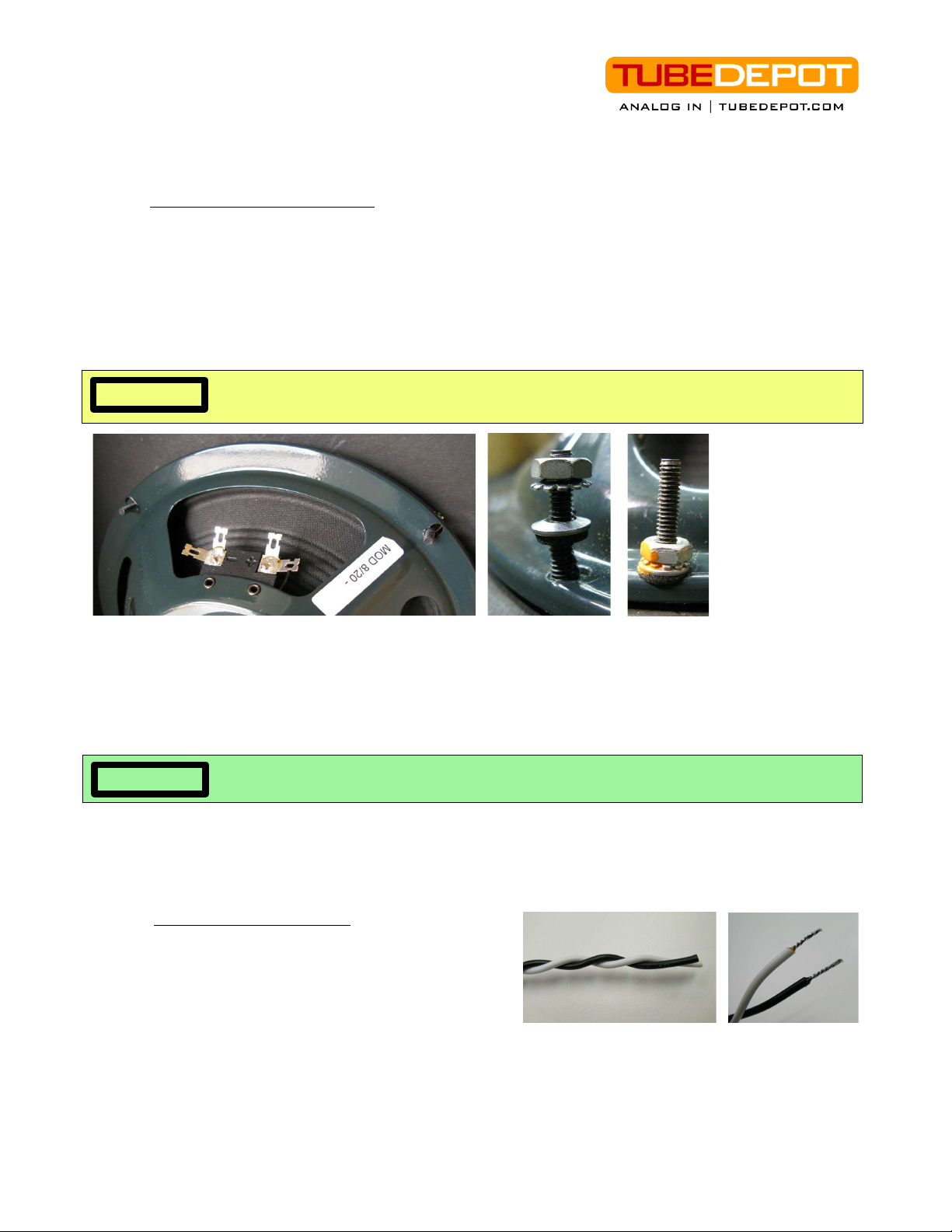
1speaker, 12" Jensen MOD, 8ohms
1chassis, steel chrome plated 5E3
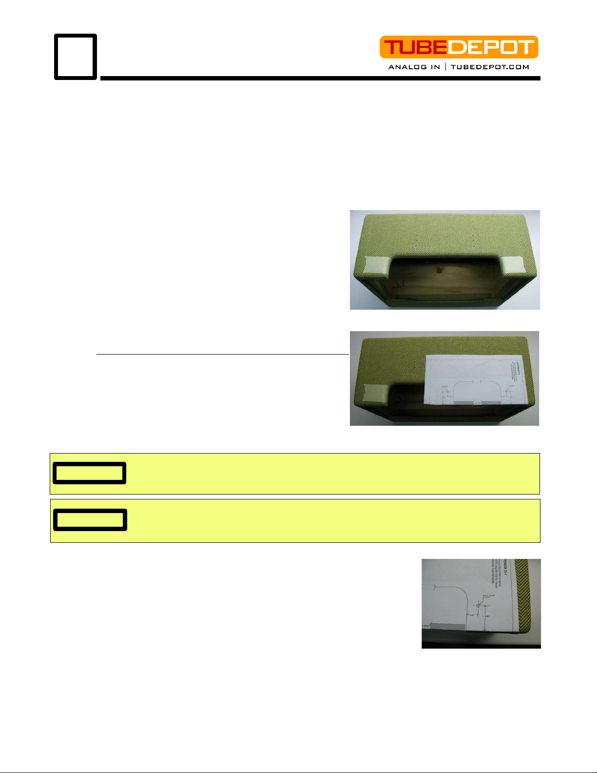
1cabinet, tweed 5E3
1PCB board, 5E3
Transformers
1 tPower transformer, ClassicTone 18017
1 Output transformer, Classictone 18002
Tubes
15AR4 / GZ34 rectifier tube various brands
26V6GT beam power tetrode various brands
212AX7 / ECC83 dual triode various brands
Hardware, Cabinet (provided with cabinet)
4 bolt 1 1/2” 6x32 copper plated truss screw baffle mounting bolts
4 bolt 1 1/2” 8x32 flat head, black oxide coated speaker mounting bolts
4nuts, KEPS 6x32 baffle mounting nuts
4nuts, KEPS 8x32 speaker mounting nuts
1 handle, brown flat leather w/ mounts and screws handle assembly
4 feet, metal glide w/ screw glide feet
8 screw, #6 oval head phillips, 1 1/4” stainless steel back panel screws
Hardware, General
3knob, vintage pointer volume and tone knob
1fuse holder, conical cap, vintage style fuse holder
2fuse, 3AG 2A slow-blow fuse (one extra fuse)
1lamp holder indicator lamp holder
1jewel, red red jewel
1lamp, #47, 6.3 V lamp
4jack, 12A, shorting, Switchcraft ¼" input jacks
2jack, 11A, open, Switchcraft ¼" speaker output jacks
9washer, lock; 3/8" lock washer for jacks and potentiometers
1plug, Switchcraft ¼" speaker phone plug
2switch, toggle SPST; Carling power and standby switches
2washer, lock 1/2” lock washer for switches
1power cord, grounded three prong, 12' power cord
1strain relief, Heyco strain relief
1nylon cable clamp cable clamp
1screw, zinc plated #8 x 5/8", phillips flat head cable clamp screw
2screw, zinc plated 6-32 x 3/8", phillips pan head V1 tube socket shock mounting
2washer, flat zinc plated, #6 screw V1 tube socket shock mounting
2grommet, rubber 1/4" chassis hole / #6 screw V1 tube socket shock mounting
2grommets, rubber 3/8" hole rubber chassis grommets
4washer, neoprene bonded speaker mounting
2bolt, 1 1/2" 1 x32 truss screw chassis mounting
2nuts, KEPS 1 x32 chassis mounting
1 screw, zinc plated 6-32 x 1/4", phillips pan head tube socket mounting
13 nuts, KEPS 6x32 tube socket / PC board mounting
2nuts, 6x32 preamp tube socket mounting
4screw, zinc plated 6-32 x 1/2" phillips pan head PC board mounting
4standoff, nylon; L = .25"; id = .14 "; od = .25 " PC board mounting
4nuts, KEPS 8x32 power / output xfmr mounting
2nuts, 8x32 power xfmr mounting
TubeDepot.com 3
Parts Inventory
3
TubeDepot.com
1958 Vanderhorn Dr.
Memphis, TN 38134
(877) 289-7994

2screw, zinc plated 8-32 x 1/4", phillips pan head output xfmr mounting
1screw, zinc plated #6 philips pan head back panel ground connection
2solder lug, locking, #8 screw power xfmr mounting / chassis ground
2solder lug, locking, #6 screw preamp tube socket mounting / chassis ground
1header, 3 pin / two position feedback select
1shorting jumper feedback select
3 ft. alum. tape, 2" width, self adhesive electrical and temperature shieldin
2heat shrink, 1/8" - black, 6" piece insulation, wire dressing
2 wire nut, 2 AWG – 14AWG AC wiring
2 rubber foot, clear adhesive PC board anti-vibration
Tube Sockets
2socket, tube, miniature 9 pin preamp tube sockets
3socket, tube, octal, 8 pin power and rectifier tube sockets
Resistors
21 , 1/2w carbon film pseudo filament center tap
182 , 1/2w carbon film cathode resistor
468K, 1/2w carbon film input resistor
31M, 1/2w carbon film preamp tube grid biasing
31 K, 1/2w carbon film plate resistor
41.5K, 1/2w carbon film cathode resistor
256K, 1/2w carbon film bias resistor
222 K, 1/2w carbon film power tube grid biasing
12.7K, 1/2w carbon film feedback resistor
147, 1/2w carbon film feedback resistor
125 , 5w metal oxide power tube cathode resistor
14.7K, 3w metal oxide B+ voltage divider resistors
122K, 1w metal oxide B+ voltage divider resistors
247 , 2w metal oxide screen grid resistors
Capacitors
15 pfd / 5 V tone capacitors
1. 47ufd / 63 V tone capacitors
1. 22ufd / 63 V coupling capacitors
4.1ufd / 63 V coupling capacitors
1. 1ufd / 63 V coupling capacitor (alternate for C7 cap)
322ufd / 5 V cathode bypass capacitors
322ufd / 5 V power supply filter capacitors
Potentiometers
31M audio volume and tone controls
Wire
1 ft wire, 2 awg, stranded, hi-temp PVC – yellow general signal wiring
8 ft. wire, 2 awg, stranded, hi-temp PVC – red B+ and input signal wiring
8 ft. wire, 2 awg, stranded, hi-temp PVC – black ground
4 ft. wire, 18 awg, stranded, hi-temp PVC – green filament wiring
2 ft. wire, 18 awg, stranded, hi-temp PVC – black speaker
2 ft. wire, 18 awg, stranded, hi-temp PVC – white speaker
1 ft. wire, 2 awg, solid buss wire, tinned copper ground wire across volume and tone controls
-----------------------------------------------------------
4 TubeDepot.com

This chapter deals with preparing the cabinet for installation of the completed chassis. But
first, we need to take inventory of the parts that came installed on the cabinet.
1. Handle w/ mounting hardware – There should be a single flat brown leather handle
with two metal securing ends all fastened to the cabinet with four screws.
2. Feet, chrome metal glide – There should be four metal feet attached with screws to
the underside of the cabinet.
3. Back panels, upper and lower with screws – There should be two back panels. The
top back panel should be secured with four panel screws, the bottom panel should be
secured with four panel screws.
4. Baffle bolts with nuts – There should be four
bronze plated bolts attaching the baffle to the
cabinet. The baffle is secured with four KEPS
nuts, one on each of these bolts.
5. Speaker bolts with nuts – There should be four
black oxide coated bolts for securing the speaker
to the baffle board. Additionally, there should be
four KEPS nuts, one on each of these bolts to be
used when mounting the speaker.
Drilling for the Chassis Mounting Bolts
Step 1 – Remove the amp handle from the top of
cabinet and remove the top back panel.
Step 2 – Apply masking tape on each side of cabinet
opening (photo 4.1a).
Step 3 – Remove template page from manual (appendix
D1) and fold on indicated line.
Step 4 – Place template on top of cabinet. Properly align over the right opening (photo 4.1b).
Step 5 – With a pointed tool, make a mark through the template at the
cross hair points marked “drill 3/16” (photo 4.1c). Press lightly into the
tape and cabinet. This mark should be just deep enough to see the
mark on the masking tape underneath.
Step 6 – Repeat step 4 & 5 for the left edge
Step 7 – Remove the template. With a ruler or scale, check and verify
that the marks are properly aligned on the cabinet top as referenced to
the measurements on the template.
Step 8 – If the marks are verified correct, drill the two 3/16” holes, one
at each of these two marks all the way through the top of the tweed cabinet.
Step 9 – Remove the masking tape and clean up any loose splinters and / or tweed from the
Be certain of template placement before drilling. The rounded edges of the cabinet can skew
measurements and cause improper placement. Always measure several times before
drilling.
CAUTI N
photo 4.1a
photo 4.1b
4.1
4Cabinet Preparation
photo 4.1c
TubeDepot.com 5
Some printers may automatically reduce the size of the template when printed. Therefore,
prior to use, always physically measure the printed template to insure proper scale is
maintained.
CAUTI N

holes and install the chassis mounting bolts.
Step 10 – Test fit the chassis onto the bolts to make sure the
holes are properly aligned.
Step 11 – Remove chassis and reinstall handle, leaving chassis mounting bolts installed.
Proceed to 4.2
Installing the Speaker
Step 1 – Remove the four nuts from the speaker mounting bolts inside the cabinet.
Step 2 – Remove the speaker from its shipping box. With speaker in hand, carefully align the
speaker mounting holes to the baffle bolts. I recommend installing the speaker with
connecting terminals on top.
Step 3 – Slowly press the speaker onto these bolts, being certain that the bolts are
proceeding through the mounting holes of the speaker equally (photos 4.2a).
Step 4 – Once the speaker is installed on the bolts, install the neoprene bonded washers
(photo 4.2b) and press the bonded washer fully against the speaker frame.
Step 5 – Once the neoprene bonded washers are mounted on the bolts, install and tighten
the KEPS nuts.
Step 6 – With the nuts and washers tight, I recommend using a small dab of fingernail polish
to further guarantee that the nuts do not come loose or the lock washer buzzes (photo 4.2c).
Proceed to steps 4.3
Wiring the Speaker
Step 1 – Twist the two 15” lengths of black and
white wire together (photo 4.3a).
Step 2 – At one end, strip the insulation back ½ ”
from both wires and tin these two wires (photo 4.3b).
Step 3 – Unscrew the barrel of the ¼ ” phone plug.
Step 4 – Solder the two tinned wires to the plug; white to center and black to shield (photo
4.3c). Reinstall plug barrel.
Step 5 – At the opposite end of the twisted wire pair, strip back the insulation ¼” and tin these
two wires.
Alignment of all holes during speaker installation is crucial Otherwise, one or more of the
bolts may accidentally puncture the speaker cone.
CAUTI N
photo 4.2a
4.2
4.3
6 TubeDepot.com
photo 4.3a
photo 4.3b
CAUTI N It is important to fully tighten the KEPS nuts so that the lock washer around the nut does not
spin. If loose, this lock washer will cause a vibrational “buzz” when the amp is played.
photo 4.2b photo 4.2c

Step 6 – Solder these wires to the solder terminals of the speaker;
the white wire to the “+” terminal and the black wire to the “-”
terminal (photo 4.3d).
Proceed to 4.4
Installing the Shielding Tape
Step 1 – Place the removed back panel with the tweed side toward
the desk and the wood side facing up.
Step 2 – Cut the aluminum shielding tape strip into two equal
lengths of 16”
Step 3 – Remove the backing from the first of the shielding tape
strips.
Step 4 – Apply the aluminum tape to the back of the
panel. Leave 1/8th of an inch space at the top of the
panel and center the strip between the two panel edges
(photo 4.4a).
Step 5 – Remove the backing from the second
shielding tape strip and apply the tape to the back of
the panel similar to the previous strip. Align the edge of
the tape along the bottom edge of the panel, offset by
1/8th of an inch from the bottom edge of the panel and
overlapping the second strip (photo 4.4b).
Proceed to chapter 5
CAUTI N Once the backing is removed from the aluminum tape, the tape will have a tendency to curl.
Be sure to keep the tape straight to avoid having the tape stick permanently to itself.
photo 4.3d
4.4
photo 4.3c
photo 4.4b
N TE
The ¼” phone plug was invented for use in telephone
switchboards in 1878. Although it is no longer used for
telephone switching, this great plug has become the
standard connection type between musical instruments
and outboard equipment.
TubeDepot.com 7
photo 4.4a

Here is where good soldering skills and attention to detail will pay off. By following these
directions, you should have no trouble in completing the circuit assembly quickly and without
errors.
I encourage you to first read all the steps to familiarize yourself with not only the installation
flow, but also the components to be used. Appendix A has explanations on how to read the
value codes found on both the resistors and capacitors. Appendix B has helpful hints on
improving your soldering skills.
Printed Circuit Board (PCB) Assembly
Installing the Components
This PC board was designed for both great tone and ease of assemble. This PC board
layout closely follows the original point-to-point layout in order to duplicate any tone shaping
created by component and wiring proximity interactions. Additionally, there are built-in
modification options available exclusively with this board. With over-sized traces and
through-hole plating, this board will provide years of trouble free life.
Resistors
Step 1 – Gather all components together. Separate the components by type (resistors,
capacitors, header, jumper, and wire). Install resistors first. Resistors have no polarity and can
be installed in either direction.
Step 2 – Install a 82 ohms / ½ watt resistor (gray, red, brown, gold) in R9 position.
Step 3 – Install 68K (68 ) ohms / ½ watt resistor (blue, gray, orange, gold) in positions R1,
R2, R4, and R5.
Step 4 – Install a 1 K (1 , ) ohms / ½ watt resistor (brown, black, yellow, gold) in
positions R8, R7, and R1 .
5Circuit Assembly
N TE For hints on improved soldering skills, review Appendix B at the end of this manual.
Additionally, visit: http: www.youtube.com user TubeDepotTV and watch “How To Solder”.
8 TubeDepot.com
CAUTI N Once soldered, be sure to clip all component leads close to the circuit board. If the leads are
too long, they risk shorting or arching against the chassis when the PCB is installed.
The PC board in this
photo is version 3.1. The
present version is 3.6
5.1

Step 5 – Install a 2.7K (2,7 ) ohms / ½ watt resistor (red,
violet, red, gold) in position R23.
Step 6 – Install a 47 ohms / ½ watt resistor (yellow, violet,
black, gold) in position R24.
Step 7 – Install 1.5K (1,5 ) ohms / ½ watt resistors (brown, green, red, gold) in positions
R12 & R14.
Step 8 – Install 22 K (22 , ) ohms / ½ watt resistors (red, red, yellow, gold) in positions
R17 and R18.
Step 9 – Install a 1M (1, , ) ohms / ½ watt resistor (brown, black, green, gold) in
position R13.
Step 10 – Install a 56K (56, ) ohms / ½ watt resistor (green, blue,
orange, gold) in positions R11 and R15.
Step 11 – Install a 22K (22, ) ohms / 1 watt resistor (red, red,
orange, gold) in position R22.
Step 12 – Install a 4.7K (4,7 ) ohms / 3 watt resistor (yellow, violet,
red, gold) in position R21.
Step 13 – Install a 25 ohms / 5 watt (or upgrade to the 8W Brown
Devil) resistor in position R2 (photo 5.1a).
Capacitors
Step 14 – Install a . 22ufd coupling capacitor (223) in position C7. It is important to install the
capacitor leads in the two holes as shown in photo 5.3b. This capacitor does not have a
polarity and can be installed in either direction.
Step 15 – Install a .1 ufd coupling capacitor (1 4) in positions C1, C2, C8 and C9. These
capacitors do not have a polarity and can be installed in either direction.
Step 16 – Install a 22ufd / 5 V electrolytic capacitor in positions C3, C6, and C1 . These
components have a polarity, therefore they must be installed according to case and board
markings. The arrow points to the negative lead.
Step 17 – Install a 22ufd / 5 V electrolytic filter capacitor in positions C12, C13, and C14.
These components have a polarity, therefore they must be installed according to case and
board markings (photo 5.3b).Proceed to 5.2 TubeDepot.com 9
CAUTI N Electrolytic capacitors DO have a polarity and must be installed according to the markings
on the component and the PC board. The arrow on the case points to the negative lead
The on-board positions for all coupling and electrolytic capacitors have additional pads for
accommodating different lead spacings of different sized components. It is recommended to
utilize the pad spacings that closely match the leads of the component you are installing.
N TE
When installing electrolytic caps, it is good practice to install the component with the value,
voltage rating, and polarity markings facing up. This makes reading the component easier.
N TE
N TE
Position C7 is critical to overall tone shaping of the amp. If after you have assembled the
amp the tone is too muddy sounding, try changing C7 value to .01 or .0047 to reduce the low
end response of the amp. I usually install a .01 ufd cap here by default.
N TE
When installing large electrolytic caps, it is good practice to secure the component to the
board with a small bead of silicon adhesive. This will keep the component firm against the
board, removing the chance for the component to vibrate when the amp is played.
N TE
Many small tube amps from the late 50's into the mid 60's used Ohmite “brown devil”
resistors as the cathode resistor of the power tube(s). Although more expensive, this is the
preferred resistor to use because of its durability and small size. And it looks great too!
photo 5.1a

Installing Feedback Header / Jumper J1
Step 1 – Locate position J1 on the board. It is identified by the
three small pads next to the printed word
“feedback”, above the large letter “G”.
Step 2 – Install the three pin header in these three
holes (photo 5.2a / b).
Step 3 – Install the jumper onto the two pins
nearest R23 (the “out” position).
Proceed to 5.3
Installing the Cathode Bias Jumper
Step 1 – Locate the small box labeled “G5 / aa” printed in the middle of the
circuit board.
Step 2 – With a small length of bare wire (a cut component lead will do
great), connect (jumper) these two pads (G5 and aa) together and solder
(photo 5.3a ).
Proceed to 5.4
Installing the Wires to the Board
5.4.1 Black Wires (Grounding)
Step 1 - Strip back the insulation 1/8” from the end of a black 2 AWG wire. Tin the end of
the exposed strands. Insert the tinned end of this wire into the pad labeled “G1” on the PC
board top (where the components are mounted) and solder into place. Measure and cut this
wire to a length of 3” from pad G1.
Step 2 – Repeat the above for pad “G2”.
Step 3 – Repeat above for pad “G7” except extend wire to 4”.
Step 4 – Repeat above for pad “G1 ” except use 6” of 18AWG wire.
Proceed to 5.4.2
5.2
10 TubeDepot.com
5.3
photo 5.2b
photo 5.2a
photo 5.3a
photo 5.3b – filled board
5.4
The PC board in this
photo is version 3.1. The
present version is 3.7
When installing the wire,
the ends of the wires are
inserted into the pads on
the top of the PC board
and soldered from
underneath
N TE With the FEEDBACK jumper in the “OUT” position, the amp will have stronger midrange
response and be quick to distort. This is the stock setting. With the jumper in the “IN”
position, the amp will be cleaner, with a flatter frequency response and better low end punch.

5.4.2 Red Wires (Circuit B+ and Preamp Tube Inputs)
Step 1 - Strip back the insulation from the end of the red wire
1/8” and tin the end of the exposed strands. Insert the tinned
end of this wire into the pad labeled “a” and solder. Measure and cut this wire to a length of 3”
from pad “a”.
Step 2 – Repeat above for pads “b”, “d”, and “e”.
Step 3 – Repeat above for pads “x” and “y” except extend the wires to 3.5”.
Step 4 – Repeat above for pad “j” except extend the wire to 3.5”.
Proceed to 5.4.3
5.4.3 Yellow Wires (General Signal Routing)
Step 1 - Strip back the insulation from the end of the yellow wire 1/8” and tin the end of the
exposed strands. Insert the tinned end of this wire into the pad labeled “h” and solder.
Measure and cut this wire to a length of 3” from pad “h”.
Step 2 – Repeat above for pads “m”, “n”, “r”, “s”, “u”, “v”, “w”, and “z” except extend the wire
to 3.5” for each.
Step 3 – Repeat above for pad “c” and extend the wire to 5”.
Step 4 – Repeat above for pads “f” and “t”, except extend the wires to 6”.
Step 5 – Repeat above for pad “q” except extend the wire to 7”.
Step 6 – Repeat above for pad “p” except extend the wire to 9”.
Proceed to 5.5
Installing the Anti-Vibration Bumpers
Step 1 – Remove one of the clear plastic bumpers from its backing and stick it near the
center of the PC board. Avoid attaching it to any component pads.
Step 2 – Remove the remaining bumper from its backing and stick it on top of the first bumper
already attached to the PC board (photo 5.5a).
Proceed to Chapter 6
TubeDepot.com 11
5.5
N TE In order to keep mechanical vibrations to a minimum, I recommend installing the two plastic
bumpers on the underside of the PC board prior to installing in the amp.
photo 5.5a

Drilling Mounting Holes for the Printed Circuit Board (PCB)
There are two acceptable methods for
determining where to drill the holes for
mounting the circuit board, the template
method (6.1.1) and the positional method
(6.1.2). Choose the method that works best
for you.
6.1.1 Template Method
Step 1 – Locate the template “drilling
template chassis/5E3” in Appendix D2. Verify that the template drill markings correctly align
with the PC board mounting holes.
Step 2 – Once verified, situate the chassis with the large chrome side facing up and the
printed control panel facing toward you. Place the template onto the chassis. Make sure the
template markings line up with the actual chassis edges.
Step 3 – On the template, locate the four concentric circular drill indicators (photo 6.1a).
Step 4 – With a sharp, hardened tool (center punch is great), make a mark at the center of
these drilling indicators, leaving an identifiable indentation / mark on the chassis (photo 6.1b).
Step 5 – Utilizing the printed measurements from the template, verify that these marks are
correctly situated on the chassis.
Step 6 – Once verified, drill four, 5/32” holes, one hole at each of these marked spots.
N TE Use a new drill bit when drilling this chassis. Go slowly through the steel at a low rotational
speed. A little drop of light oil at each drilling point helps too. These practices will allow the
metal to be cut cleanly with minimal formation of burrs.
A sharp, large nail and hammer make a great make-shift center punch. By placing the nail
on the template mark and firmly tapping the head of the nail with the hammer, the resultant
mark in the metal is great for accurately guiding the drill bit into the chassis.
N TE
6Chassis Preparation
6.1
photo 6.1b
photo 6.1a
Some printers may automatically reduce the size of the template when printing. Therefore,
prior to use, always physically measure the printed template to insure proper scale is
maintained.
CAUTI N
Step 7 – Remove any burrs around holes. A deburring tool is very
helpful here. Verify results by lining up mounting holes with PC
board.
Proceed to step 6.2
6.1.2 Positional Method
Step 1 – Situate the chassis with the large chrome side facing up
with the printed control panel facing toward you.
Step 2 - Apply a 1” strip of masking tape across chassis, situated
between the hole for the output transformer secondary and the
mounting hole for the output transformer (photo 6.1c).
Step 3 – Divide the distance between the edges of these two
holes (5/8” is middle) and place a mark on the masking tape
(photo 6.1c).
12 TubeDepot.com
photo 6.1c

Step 4 – Place the circuit board on the chassis. Align one
of the short edges of the circuit board against the mark on the
masking tape and center the two long edges equally between
the two chassis sides (photo 6.1d).
Step 5 – With a permanent marker, place a mark on the chassis
through each of the four holes at each corner of the circuit board.
Step 6 – Remove the circuit board. With a center punch (or
something similar), place a solid mark into the chassis at each of
the permanent marker points.
Step 7 – Lay the circuit board onto the chassis and verify that the marks line up correctly with
the four corner mounting holes of the circuit board.
Step 8 – Once verified, remove the circuit board and drill four, 5/32” holes, one hole at each
of these marked spots.
Step 9 – Remove any burrs around holes. A deburring tool
is very helpful here. Verify results by lining up mounting
holes with PC board. Proceed to step 6.2
Mounting the Power Transformer
Step 1 – Loosely twist all power transformer wires together
and slowly guide the wire bundle through the chassis
opening. Twist both yellow wires together, both red wires
together, and both red/yell & red/blu striped wires do not
get twisted. For 120v/60hz operation the blk/wht striped
wire gets twisted with blk wire, solid wht gets twisted with
wht/blk. For 240v see Diagram 6.2a
Step 2 – Situate the transformer so that the primary wires (blk/wht,solid wht & blk,wht/blk) are
nearest to the fuse holder. Next, connect your ac cords white neutral to the transformer's wht & wht/
blk wire from your transformer then solder & heatshrink the exposed area. Now connect solid blk &
blk/wht wires to the power switch (use the tab on the side opposite of the fuse holder).
Step 3 – Install and tighten two #8 KEPS nuts on the transformer mounting bolts nearest the edge
side of the chassis (photo 6.2a).
Step 4 – Bend the two #8 solder tabs at a slight angle (photo 6.2b).
Step 5 – Install these tabs on the remaining two transformer bolts, oriented at angles toward the
chassis edges (photo 6.2a).
Step 6 – Install the two #8 standard nuts on these two bolts with the solder tabs (photo 6.2a).
Proceed to 6.3
Installing the Rubber Grommets
Step 1 – locate the two 3/8” rubber grommets
and the two corresponding holes on the chassis.
Step 2 – Insert the two rubber grommets in the
chassis holes (photos 6.3a and 6.3b).
6.3 photo 6.3a
6.2
TubeDepot.com 13
N TE
A sharp, large nail and hammer make a great make-shift center punch. By placing the nail
on the permanent marker mark and firmly tapping the head of the nail with the hammer, the
resultant mark in the metal is perfect for accurately guiding the drill bit into the chassis.
N TE Use a new drill bit when drilling this chassis. Go slowly through the steel at a low rotational
speed. A little drop of light oil at each drilling point helps too. These practices will allow the
metal to be cut cleanly with minimal formation of burrs.
Diagram 6.2a
photo 6.3b
photo 6.1d

Proceed to 6.4
Mounting the utput Transformer
Mounting the three 1M potentiometers
Step 1 – Locate the three 1M potentiometers and the three
3/8” lock washers.
Step 2 – Remove the nut and flat washer from each pot.
Remove the keying tab (by cutting off or bending out of the
way) flush from each pot (photo 6.5a)
Step 3 – Install a lock washer on each pot (photo 6.5b).
Step 3 – Insert each pot with appropriate lock washer
into corresponding hole in chassis (lock washer should be on the inside of
chassis).
Step 4 – Rotate each pot where solder terminals are facing toward the
outside of the chassis (photo 6.5c)
Step 5 – Tighten all nuts with a 1/2” socket.
Proceed to 6.6
Mounting the Indicator Lamp
Step 1 – Remove the nut from the bezel holder.
Step 2 – With the nut removed, remove the lamp frame.
Step 3 – Place the bezel holder through the corresponding opening in the
chassis.
Step 4 – Install the lamp holder on the threaded end of the bezel holder.
Step 5 – Thread the nut onto the threaded end of the bezel holder.
Step 6 – Position the indicator lamp with the lamp frame toward the chassis
(photo 6.6a).
Step 7 – Tighten the nut to firmly secure the assembly to the chassis.
Step 8 – Apply a drop of fingernail polish to the threads and nut to lock in place (photo 6.7a).
Proceed to 6.7
6.4
14 TubeDepot.com
6.5
6.6
By placing the point of a center punch on one of the corners of the lamp assembly nut and
tapping the center punch, the nut can be firmly tightened
N TE
Step 1 – Twist the primary wires together (red, brown and blue).
Step 2 – Twist the secondary wires together (Green & black).
Step 3 – Feed the two wire sets into the grommets (photo 6.4a).
The red, blue and brown primary wires go into the grommet
nearest the power transformer (see appendix F for various photo 6.4a output
transformer wiring options).
Step 4 – Pull the two wire bundles tightly through the grommets
Step 5 – Secure the output transformer to the chassis with two #8 KEPS nuts and the two #8
x 1/4” screws. The two KEPS nuts should be mounted on the inside of the chassis. Proceed
to 6.5
photo 6.5a
photo 6.6a
photo 6.5b
photo 6.5c
remove this tab
N TE
The various output transformers available with this kit
have differing wire colors.. Refer to appendix F for
applicable installation directions and options.

Mounting the Fuse Holder
Step 1 – Remove the nut from the fuse holder and insert the
fuse holder into the corresponding chassis opening. The rubber gasket should be situated on
the outside of the chassis.
Step 2 – Reinstall the threaded nut on the fuse holder and tighten it against the chassis.
Step 3 – Keep the nut from loosening by painting the exposed threads with fingernail polish
(photo 6.7a).
Proceed to 6.8
Mounting the Power Switch
Step 1 – Remove all mounting nuts from the switch.
Step 2 – Reinstall the knurled round nut, threading it to the
body of the switch (photo 6.8a).
Step 3 – Install the large 1/2” lock washer on the switch.
Step 4 – Install the switch into the appropriate hole in the
chassis with the solder terminals facing up (photo 6.8b).
Step 5 – Thread the hex nuts onto the exposed switch threads and tighten firmly.
Proceed to 6.9
Mounting Ground / Standby Switch
Step 1 – Remove all mounting nuts from the switch.
Step 2 – Reinstall the knurled round nut, threading it to the body
of each switch (photo 6.8a).
Step 3 – Install the large 1/2” lock washer on each switch.
Step 4 – Install the switches into the appropriate holes in the
chassis with the solder terminals facing up (photo 6.8b).
Step 5 – Thread the hex nuts onto the exposed threads and tighten with a 9/16” socket.
Proceed to 6.10
Mounting the ctal Tube Sockets
Step 1 – Prior to mounting, slightly bend the solder terminals on the back of the socket
outward (photo 6.1 a).
Step 2 – Insert the three sockets from the outside of the
chassis. Rotate these three sockets so that Pin 2 is
closest to the chassis edge.(photo 6.1 b).
Step 3 – Secure each of the three sockets to the chassis
with two #6 x 1/4” screws and two #6 KEPS nuts.
Proceed to 6.11
Installing and Wiring the Speaker Jacks
Step 1 – Install a lock washer on each speaker jack and then install the two
1/4” Switchcraft 11A jacks into the appropriate speaker jack chassis holes.
Step 2 – Align the jacks in the chassis with “tip” terminals facing each other (as shown in
photo 6.11a).
The terminals of these sockets will break if bent too far. It is recommended to use needle
nose pliers for better control when bending these terminals.
CAUTI N
Photo 6.10a
Photo 6.10b
6.8
Pin 2 -----
TubeDepot.com 15
Photo 6.8a
Photo 6.8b
6.10
6.11
6.9
Photo 6.7a
6.7

Step 3 – Place the flat washer on the outside of the chassis
and then install and tighten the hex nuts with a 1/2” socket.
Step 4 – Locate the output transformer secondary wires (either a
black wire and green wire; black wire and yellow wire; or possibly
even black, yellow, and green wires.). Trim to length and solder the
black wire to the grounding terminal of the jack nearest the power
tube sockets (photo 6.11a).
ee appendix “F” for additional output transformer wiring
options
Step 5 – Run the 8 ohm tap wire to the output jacks and trim to length.
Step 6 – Strip (1/4”) and tin this 8 ohm tap wire.
Step 7 – With the 8 ohm tap wire, connect the two positive (tip) terminals of the speaker jacks
together (photo 6.11a).
Step 8 – Do not solder these wires just yet,. There is one more wire to add in a future step
(the yellow wire from the board as seen in photo 6.11a). Proceed to 6.12
Mounting the 9 pin Tube Sockets
Step 1 - Prior to mounting the preamp tube sockets, slightly bend the solder terminals 1 - 3
and 6 – 9 outward, leaving pins 4 and 5 alone for now.
Step 2 – Carefully bend terminals 4 and 5 together. The holes of these
terminals should meet close to flush against each other (photo 6.12a).
Step 3 – To provide a flat surface for the mounting screws, use a pair of
needle nose pliers to carefully bend the edges of the shield near the screw
mounting holes in toward the socket (photo 6.12b, c, and d).
Before installing these sockets into the chassis, choose either traditional
mounting or shock mounting. The
conventional option (6.12.1) is to install the
sockets directly to the chassis with screws.
However, shock mounting the sockets
(6.12.2) with rubber grommets, will greatly
reduce the effects of tube microphonics.
6.12.1 traditional socket installation
Step 1 – Insert the V2 tube socket from the outside of the chassis.
Rotate so that pin 8 of the socket is closest to the chassis edge.
Step 2 – Insert a #6 x 1/4” screw into each mounting hole of the V2
socket. Secure the tube socket with two #6 KEPS nuts tight against
the chassis.
Step 3 – Insert the V1 tube socket from the outside of the chassis and
rotate the socket so that pin 8 of the tube is closest to the chassis
edge (photo 6.12e).
Photo 6.12a
6.12
chassis edge
pin 8
photo 6.12e
Photo 6.11a
16 TubeDepot.com
The terminals of these sockets will break if bent too far. It is recommended to use needle
nose pliers for better control when bending these terminals.
CAUTI N
before after
photo 6.12a
photo 6.12c photo 6.12d
photo 6.12b
N TE
Various output transformers are available with this kit.
The wire colors differ between these transformers.
Refer to appendix F and or the TubeDepot online
resources for appropriate installation instructions.
Table of contents
Popular Recording Equipment manuals by other brands

Olimpia splendid
Olimpia splendid B1014 Installation and maintenance instruction

JVC
JVC SA-F911E instructions

HY-LINE
HY-LINE HY-Di-HBI-A1 quick start guide

Caribbean Controls
Caribbean Controls M Series quick start guide

Turbo
Turbo E4T Use and maintenance instructions

Cochlear
Cochlear CP900 Series quick guide