turbineaire 1245GT User manual

Features for the expert… Ease of use for the beginner
OPERATOR’S
MANUAL
Turbine-Powered HVLP Sprayers

Turbinaire
Operator’s Manual – Page 2 of 14
Thank you for choosing Turbinaire HVLP (High-Volume, Low-Pressure) sprayers for your spray finishing
needs. At Turbinaire, we take pride in our precision-engineered products and want you to obtain all the
benefits that your Turbinaire sprayer has to offer.
To ensure your safety and satisfaction with your Turbinaire sprayer, please carefully read the information
contained in this manual before using your system. Should you require any further information, please
contact your nearest Turbinaire distributor or Turbinaire directly at
IMPORTANT: READ BEFORE USING
SAFETY PRECAUTIONS
•CAUTION: Arcing parts. Keep the turbine at least 20 feet away from explosive vapors to avoid risk of
fire or explosion.
•Only connect the power cord to a grounded circuit.
•Never spray flammable materials near any source of open flame or spark.
•Always spray in a properly ventilated area.
•Never point the spray gun at anyone.
•Always wear a spray mask and protective eyewear and clothing when spraying toxic substances.
•Always follow the coating manufacturer’s safety precautions and instructions, and exercise extreme
caution when using materials with a flashpoint below 70º F (21º C)
•Do not use halogenated hydrocarbon solvents. Halogenated hydrocarbon solvents such as methylene
chloride and 1,1,1 – Trichloroethane are not compatible with aluminum and may cause an explosion. If
unsure of a materials compatibility with aluminum, contact your coating supplier

Turbinaire
Operator’s Manual – Page 3 of 14
THE TURBINAIRE HVLP ADVANTAGE
Turbinaire Turbine-Powered HVLP Sprayers are powered by an electric turbine that supplies a consistent
flow of high volume, low pressure air (4-8 PSI @ 110-130 CFM) to the spray gun to atomize the coating
being applied.
By spraying at low pressure, the coating does not bounce back from the surface such as with conventional
high pressure spraying systems powered by a pump or a compressor. As a result, Turbinaire systems
reduce paint consumption, virtually eliminate overspray, and offer a transfer efficiency of up to 90%, as
compared to 30-40% with conventional systems! The end results are substantial savings in material and
operating costs, a cleaner, safer working environment and a superior quality finish.
Turbinaire ® HVLP Sprayers Systems: Features, Advantages, and Benefits
•Turbinaire HVLP systems virtually eliminate overspray offering up to 90% transfer efficiency. Increased
transfer efficiency provides for a cleaner working environment and drastically reduces paint and spray
booth costs while saving time and energy.
•Turbinaire all-inclusive portable systems operate from a standard 110V or 220V power outlet for
increased versatility. With no compressor or complicated hook-up required, the user is free to spray
virtually anywhere.
•Simple design makes Turbinaire systems easy to learn, use, and particularly maintain.
•Solid construction of Turbinaire products prevent downtime and assure durability and long life.
•The warm, clean, dry air generated by the turbine eliminates airline moisture and contaminants.
•All Turbinaire systems use motors that provide the highest CFM (Cubic Feet per Minute) rating in the
industry, thus offering the highest-quality finish.
•The unique built-in Variable Speed Controller (VSC) allows the operator to control the air output of
the turbine based on the material being sprayed, helping to keep overspray to an absolute minimum –
especially when spraying light bodied material such as stain, shellac and wood finishes. Reduce the air
output of the turbine when spraying light bodied material to minimize overspray and increase the air
output when spraying heavy bodied material to ensure proper atomization.
Turbine-powered HVLP sprayers have literally changed the way people do spray finishing. Whether you
are a professional or beginner painter/finisher, we are confident that once you are familiar with your new
Turbinaire sprayer, you will enjoy the benefits of this professional tool for many years, and appreciate the
ease and simplicity of its use.

Turbinaire
Operator’s Manual – Page 4 of 14
GETTING STARTED
Thank you for choosing a Turbinaire HVLP Sprayer for your spray equipment needs. The following steps
will help you get started quickly and easily.
For a condensed version of the Operating Instructions and Spraying Tips of your Turbinaire sprayer, please
refer to the yellow sheet included with your system. If this sheet is missing or has been lost, please contact
your local Turbinaire distributor or Turbinaire directly, we will be pleased to mail, fax, or e-mail you a new
copy.
The following instructions are meant to be a guideline for success with your Turbinaire sprayer. Although
practice makes perfect, there are a number of books, videos and courses available on the market to help
you further refine your knowledge and skills of spraying in general, should you wish to do so.
TURBINE & HOSE SET-UP
1. With power switch in OFF position, place turbine as far away from the spray area as possible and
plug into a standard power outlet.
2. Uncoil the 25’ air hose and install it hand-tight to the turbine air outlet. If you purchased
TSG-3295 (optional 5’ Heavy-Duty Hose) install it first and then install the 25’ hose to the male end
of TSG-3295. If you purchased TSG-3285 (optional 5’ flex hose) remove the brass Quick Connect
Coupler from the 25’ hose and install it on the male end of TSG-3285; then connect the female end
of TSG-3285 to male end of 25’ hose.
Although the hose is designed for industrial use, it is not crushproof. Do not stand on the hose for extended
periods. Also, the hose should never be used to pull the turbine or form a sharp angle at the air outlet – this
can cause premature wear of the hose, restriction of the airflow and/or overheating of the hose.
BNB SPRAY GUN TERMINOLOGY
COATING PREPARATION
Material Flow Adjustment Screw
Fan Size Adjustment Screw
Gland Nut
Sleeve Nut
Air Cap
Fluid Tip
Cam Lever
BNB Disk: convert from
Bleeder to Non-Bleeder
by removing BNB Disk
Male Tail Piece
Pressurization Tube with Check Valve
Cup Top
Paint Cup
Pressurization Fitting

Turbinaire
Operator’s Manual – Page 5 of 14
Remove the paint cup from the gun by sliding the cam lever sideways.
Follow any special instructions from the coating manufacturer regarding preparation for spraying, and
prepare the material to be sprayed. Install a cone filter on the cup and pour in the material. For best results,
material should always be strained before spraying. The Siphon Tube Filter supplied on the Gun should
also be used when spraying fine finishes but should be removed when spraying paint – given the fine size
of its mesh it may create too much restriction and cause paint spraying to be painfully slow.
MEASURING VISCOSITY
Use the viscosity cup supplied to measure the viscosity of the material to be sprayed.
The thickness of a coating is defined by its “viscosity in seconds”. To properly measure the viscosity of a
coating, use the viscosity cup supplied with your Turbinaire sprayer.
1. Completely submerge the viscosity cup in
the coating to be measured.
2. Lift the viscosity cup out of the coating and
begin timing.
3. Measure the time in seconds until the first
break in the stream of coating pouring out of
the hole in the bottom of the cup.
4. The time lapsed will determine the viscosity
of the coating, i.e.: 25 seconds
Once you’ve measured the viscosity, use the chart below to choose the proper size Atomizing Kit for the
material to be sprayed and install it on the gun.
ATOMIZING KIT SELECTION CHART
The proper size Atomizing Kit is critical to the optimal performance of any spraying system. Needles, Fluid
Tips and Air Caps are sized together and must be changed as a set.
To select the proper Atomizing Kit, use the chart below as a guideline. For light body materials (low
viscosity), select a smaller size kit. For heavy body materials (high viscosity), select a larger size kit. For
best results, select the Kit that performs best with the trigger of the gun fully engaged.
Atomizing Kit Selection Chart
Material
Viscosity
Atomizing Kit
Wood Stain, Lacquer, Shellac, Automotive Top Coats,
Cellulose, Synthetics, Acrylic, Oil
0-20 sec
0.50 - 0.75mm
Polyurethane, Glitter Paint, Cellulose, Acrylic, Synthetic,
Lacquer, Fluorescent, Wood Stain, Creosote, Wood
Primer, Multi-Color, Latex
20-30 sec
1.00 – 1.50mm
Oil Base, Latex, Hammer Paint, Oxide Paint, Primer,
Marine Paint, Varnish, Enamel, Multi-Color, Epoxy
30-35 sec
1.50 – 2.00mm
Emulsion, Polyurethane, Oxide Paint, Zinc Rich Primers,
Adhesives, Latex, Multi-Color, Epoxy
35-40 sec
2.00 – 2.50mm
Hammers, Latex, Oil Base Primers, Enamels, Marine
Paint, Masonry Paints, Texture Coatings, Heavy Primers,
Water and Solvent Based Adhesives
40+ sec
2.50 +
Using the chart as a guideline, select and install the proper size
Atomizing Kit based on material being sprayed.
To change the Atomizing Kit:

Turbinaire
Operator’s Manual – Page 6 of 14
1. Remove Material Flow Adjustment Screw and Needle Spring
2. Pull Trigger and remove Needle
3. Remove Sleeve Nut and Air Cap
4. Remove Fluid Tip using 1/2’’ socket and ratchet
5. Reverse steps 1-4 to re-install
CONNECTING THE GUN
Install the paint cup on the gun. Connect the gun to the hose by pulling back the ring on the brass Quick
Connect Coupler and inserting the male tail piece on end of gun handle into the coupler.
NOTE: Be sure that the gun is always clean prior to being used. Any residue and/or particles left in the
paint cup and/or fluid tubes from previous use can spoil a finish and possibly affect the performance of
your sprayer.
TO BEGIN SPRAYING
1. Press the turbine power switch to the down position (variable) and turn the speed controller knob
to maximum.
If your BNB gun is set-up as a bleeder, air will now be blowing out of the Air Cap; if it’s set-up as a
non-bleeder (as supplied), air will only start when the trigger is squeezed. In either case, the cup
is now pressurized – DO NOT remove the cup from the gun when connected to the hose and the
turbine is on.
As a non-bleeder, the BNB gun has a two stage trigger: the first stage releases air through handle
and the second stage releases material from cup.
2. While squeezing the trigger to release material from the cup, slowly turn the Material Flow
Adjustment Screw (at rear of gun) counter-clockwise until the desired material flow is achieved.
To ensure consistent and even material flow across the pattern, work with the trigger as engaged
(squeezed) as possible – if material flow gets too heavy, use a smaller Atomizing Kit.
SPRAY PATTERN – DIRECTION and SIZE
Use the vertical pattern to spray left to right, the horizontal pattern to spray up and down, and the round
pattern for detail work and/or scratch repair.
To adjust the size (width) of the pattern, turn the Fan Size Adjustment Screw at the top back of the gun.
HORIZONTAL PATTERN TEST
To select the desired spray pattern,
loosen the Sleeve Nut and rotate
the Air Cap at the front of the gun.
When the Air Cap is in the
horizontal position, the spray
pattern will be vertical; when in the
vertical position, the spray pattern
will be horizontal; for a round
pattern, turn Fan Size Adjustment
Screw completely clockwise.

Turbinaire
Operator’s Manual – Page 7 of 14
1. Place the Air Cap in the vertical position and spray three or four horizontal patterns on a test piece.
Spray and hold the pattern in the same position until material builds-up and then release the trigger —
this is the only time in finishing that you’ll ever want to see a run or sag!
2. Inspect the pattern. If the material is sagging evenly across the pattern, start spraying, otherwise
consult the chart below.
Problem
Solution
Coating is running/dripping from center
of pattern
Enlarge fan size
Reduce Material Flow
Change Atomizing Kit
Coating is running/dripping from
extremities of pattern and/or pattern is in
form of figure 8
Reduce fan size
Increase Material Flow
Change Atomizing Kit
Any one of above with remote
pressure pot
Check fluid pressure in pot for +/- 4”
stream of material
Always test application speed, spraying distance, pattern size, film thickness and finish on a test piece.
THE VARIABLE SPEED CONTROLLER (VSC)
Most coatings do not require maximum air volume to be atomized. All Turbinaire systems equipped with a
VSC have a three way power switch: On/Off/On. When the switch is in the “up” position, the turbine will
operate at maximum air volume. When the switch is in the “middle” position, the turbine is off. When the
switch is in the “down” position, the VSC can be used.
The VSC allows you to adjust the air output of the turbine based on the material being sprayed – increase
air output for heavy bodied material (i.e. latex paint) and decrease air output for light body material (i.e.
stain). Using the VSC properly will reduce overspray and increase transfer efficiency, especially with light
body material like stain, shellac and wood finishes.
To use the VSC, press the power switch in the down position, turn the VSC control knob to MAX.
While spraying a test piece, slowly turn the VSC control knob counter-clockwise to gradually reduce the
air output as much as possible without affecting the desired coating thickness and finish.
You are now ready to begin spraying!
SURFACE PREPARATION

Turbinaire
Operator’s Manual – Page 8 of 14
Ensure that the surface you are spraying is clean, dry, and free from dust, oil, grease or any other
contaminant. A dirty or greasy surface will affect adhesion, can spoil a finish and is very difficult to correct
once sprayed. Do not wipe the surface with your hand – body oil may stay on the part and ruin the
surface preparation.
OPERATING and MAINTAINING THE TURBINE
All Turbinaire systems are equipped with a re-settable circuit breaker on the face of the machine. If the
turbine is not functioning properly, check your power source and/or reset the breaker by pressing it once.
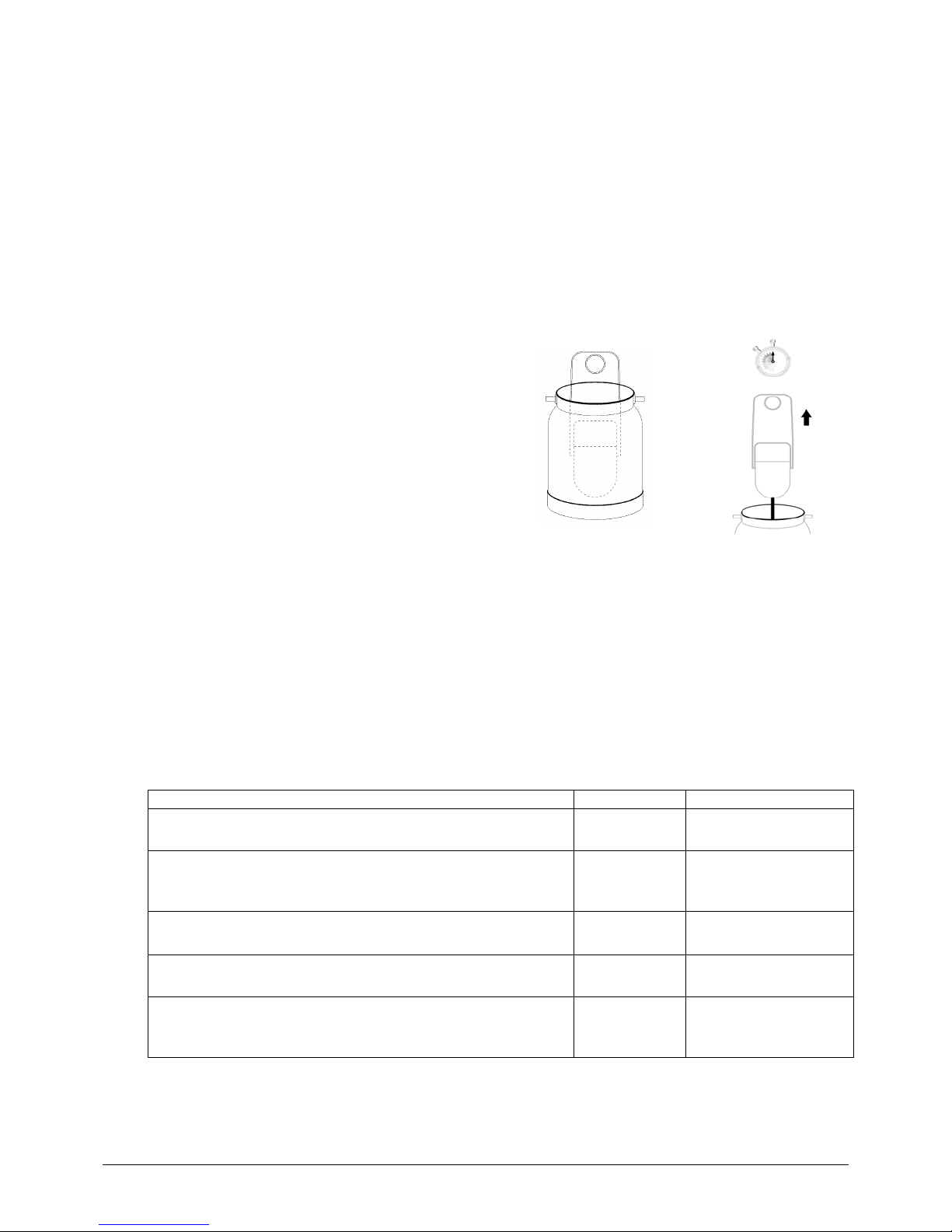
The motor inside the turbine cabinet draws large amounts of air volume. It is therefore very important to
ensure that the filters are properly installed on either side of the turbine cabinet and to check them after
every use. Blow them off with the air from the turbine after every use and clean them as necessary to
ensure that air flow is never restricted. Filters are washable however once the pores are permanently
blocked or begin to visibly deteriorate, the filters should be changed.
WARNING: Do not put wet filters in the turbine - this may cause electrical shock and/or premature wear
of the turbine. Do not operate your turbine without the foam air filters.
NOTE: Due to the high speed of the turbine (18,000 to 24,000 RPM) and the frictional forces this causes,
it is normal for the turbine to heat up during operation. Generally, the system will heat up and then remain
at a constant temperature during use.
SPRAYING TECHNIQUES
Positioning: The gun should be perpendicular to the surface at all times. Also, keep the gun upright
when there is material in the cup. You may tilt the gun as necessary to spray a ceiling or table top for
example but note that the Pressurization Tube that pressurizes the cup must remain clean in order to
push the material to the Fluid Tip. The in-line check valve on the Pressurization Tube will prevent material
from backing-up into the gun body but avoid turning the gun completely upside down when there is
material in the cup – the material may block the air hole on the underside of the Cup Top and prevent the
pressurization of the cup.
Distance: Maintain a consistent distance of +/- 6 inches from the surface and spray in a smooth
continuous motion. Moving closer to the surface may sometimes be necessary for touch-up work and fine
lines in the round pattern. Otherwise, moving closer will narrow the spray pattern and concentrate the
material to deliver a thicker coat; moving further from the surface will widen the spray pattern and any
further than 8” may result in “dry-spray”.
Direction: The direction of the spraying motion should be based on the spray pattern chosen: when
spraying a horizontal pattern, the direction should be up and down; when spraying a vertical pattern, the
direction should be left to right or right to left; when spraying a round pattern, the direction can be either.
Speed: To test the proper application speed (speed of your hand), spray one pass on a sample of the
surface to be coated at a consistent speed, then spray a second pass overlapping the first one by 50%.
Examine the overlapped section: if there appears to be space between the droplets of material, slow down
your application speed; if individual droplets are not visible and the film seems even, note the application
speed and maintain it throughout use.
Overlapping: Always overlap passes by 50%.
Correct application technique
Incorrect application technique
Correct application technique
Incorrect application technique

Turbinaire
Operator’s Manual – Page 9 of 14
Spraying Corners: When spraying outside corners, point the center of the pattern at the corner and
continue overlapping passes on adjacent surfaces by 50%. When spraying inside corners, first use a
narrow vertical or horizontal pattern (or a round pattern) to get in the corner itself and continue
overlapping passes on adjacent surfaces by 50%.
Always spray hard to reach areas, curved surfaces, and corners and edges first; spray flat surfaces last.
CLEANING AND MAINTENANCE
BASIC CLEAN-UP
If you are taking a break or plan to spray the same material again within a reasonable time:
1. Turn off the turbine and disconnect the gun from the hose.
2. Turn the Material Flow Adjustment Screw at the back of the gun clockwise until it stops and wipe
the Fluid Tip. This will ensure that the Needle closes the Fluid Tip air tight, at which point,
depending on the material, material can be left in the cup overnight or for a few days. DO NOT
leave the material in the cup if it is catalyzed or has a limited pot life.
When you are finished your spraying project, remember that the cup remains pressurized even after the
turbine is shut off and the gun is disconnected from the hose.
1. Slowly slide the Cam Lever sideways and tilt the gun to release the pressure from the cup.
2. Remove the paint cup from the gun. While removing the cup, squeeze the trigger on the gun to
drain all the material from the siphon tube into the cup.
3. Empty the excess material from the paint cup and clean it with an appropriate cleaning solvent.
4. Pour some cleaning solvent in the clean paint cup, install it on the gun and spray it into a bucket
until the spray is clear.
5. To clean the underside of the Cup Top, either shake the gun when spraying the cleaning solvent,
or use a brush with cleaning solvent to brush it clean.
6. Clean the Air Cap and the outside of the gun as necessary with a rag and cleaning solvent.
Warning: Do not submerse entire gun in cleaning solvent.
This will damage the inner components of spray gun such as o-rings and gasket that do not come in
contact with the material being sprayed.
When spraying inside and/or outside corners, spray the
center of the spray pattern on the corner so that material
is applied to each of the adjacent surfaces
Overlap passes 50%
Spraying Corners

Turbinaire
Operator’s Manual – Page 10 of 14
THOROUGH CLEAN-UP
For more elaborate cleaning (tool required: ½” hex socket and ratchet, 13/32” open-end wrench):
1. From the back of the gun, remove the Material Flow Adjustment Screw, the Needle Spring, and
the Needle by hand.
2. From the front of the gun, remove the Sleeve Nut and the Air Cap by hand, and the Fluid Tip
using a ½” socket and ratchet
3. Remove the cup from the gun and use a Gun Cleaning Brush as a pipe cleaner to clean the fluid
passages from the bottom of the siphon tube and then from the front of the gun.
4. Remove the Gland Nut using a 13/32” open-ended wrench and remove the Gland Seals
Do not use hardened needles or picks to clean the holes of the Fluid Tip or the Air Cap. This may
enlarge the holes of these critical parts and affect the performance of your system when used.
“CAUTION”: Do NOT submerse entire gun body in solvent or cleaning solutions. There are internal o-
rings /gaskets that do not come in contact with coatings being applied such as fan size adjusting
assembly and BNB Disk piston assembly. In doing so will result in damaging seals and will require
replacement of o-rings.
Once cleaning is complete, dispose of used cleaning solvent and dirty rags in a safe and environmentally
friendly way.
REPLACING THE CUP TOP GASKET
The Cup Top Gasket on the underside of the Cup Top should be replaced periodically as part of
preventive maintenance. A worn Cup Top Gasket can be the cause of material leaking from the paint cup
and/or bubbling under the paint cup top when the gun is in use.
To Replace The Cup Top Gasket:
1. Remove the Paint Cup from the gun.
2. Remove the Cup Top Gasket using a pointed object or screwdriver.
3. Replace with a new gasket, making sure it is placed flat and properly pressed in place.

Turbinaire
Operator’s Manual – Page 11 of 14
TROUBLESHOOTING
Problem
Probable Cause
Solution(s)
Turbine not working at all
A. No power to the turbine
B. Re-settable breaker has
been activated
A. Check power outlet/socket
B. Re-set breaker on face of
turbine by pressing it once
Low Air Flow
A. Filters are blocked
B. Turbine air vents are
obstructed
C. Kink in hose
D. Broken or damaged hose
E. Motor mounts broken
F. Motor outlet coupler leaking
air
A. Clean or replace filters as
necessary
B. Allow air to flow freely around
turbine
C. Remove kink and straighten
hose or replace
D. Inspect hose: repair or
replace if necessary
E. Open turbine cabinet and
inspect: replace if possible or
contact Turbinaire
F. Remove cabinet cover and
tighten screw clamps
Uneven Spray Pattern
A. Air Cap holes plugged
B. Dry paint on Fluid Tip
C. Inappropriate Atomizing Kit
D. Needle and Fluid Tip
different sizes
A. Clean or replace Air Cap as
necessary
B. Clean Fluid Tip and continue
spraying
C. Use Atomizing Kit that allows
for working with trigger fully
engaged
D. Ensure that Needle and Fluid
Tip are same size at all times
Fluid Leaking From Paint Cup
and/or Bubbling In Paint Cup
A. Cup Top Gasket not sealing
properly
A. Tighten cup or replace Cup
Top Gasket
Fluid Leaking Between Gland
Nut And Needle Directly In Front
Of Trigger
A. Gland Nut too loose
B. Gland Seal worn out
A. Tighten Gland Nut
B. Replacing Gland Seals
Not Spraying At All or
Inconsistent Material Flow
(spitting) With A Cup Gun
A. Dry paint on end of Fluid Tip
B. Material is too thick: not
enough pressure to pump
from cup to Fluid Tip
C. Foreign/unwanted particles in
the coating
D. Air Pressure Feed Tube
blocked: preventing
pressurization of paint cup
E. Cup Top Gasket not sealing
properly
F. Not enough paint in cup
A. Clean Fluid Tip and continue
spraying
B. Add thinning solvent if
possible or use remote
pressure pot
C. Empty cup; clean gun;
properly filter material when
pouring back into cup
D. Remove cup; connect gun to
hose and make sure air is
blowing through hole on
underside of Cup Top
E. Tighten cup or replace Cup
Top Gasket
F. Check level and add

Turbinaire
Operator’s Manual – Page 12 of 14
Not Spraying At All or
Inconsistent Material Flow
(spitting) With A Pressure-Fed
Gun
A. Dry paint on end of Fluid Tip
B. Insufficient pressure in paint
tank
C. Fluid Line blocked
D. Fluid Line kinked
E. Paint Tank not properly
sealed
F. Not enough paint in tank
A. Clean Fluid Tip and continue
spraying
B. Increase pressure in paint
tank
C. Disconnect Fluid Line from
gun and place in bucket;
increase air pressure in tank
to flush hose.
D. Remove kink and straighten
as necessary
E. Tighten Wing Nuts on paint
tank or replace gasket if
necessary
F. Check level and add
Paint Leaking From Fluid Tip
A. Damaged Needle and/or
Fluid Tip
B. Needle and Fluid Tip
different sizes
C. Gland Nut too tight
A. Check and replace if
necessary
B. Ensure that Needle and Fluid
Tip are same size at all times
C. Loosen Gland Nut
Excessive Overspray
A. Too much air volume for the
coating being sprayed
B. Spraying too far from the
surface
A. Use Variable Speed
Controller to reduce air
volume output of turbine
B. Hold gun +/- 6” from the
surface when spraying

Turbinaire
Operator’s Manual – Page 13 of 14
TROUBLESHOOTING FINISH PROBLEMS
Problem
Probable Cause
Solution(s)
Runs or Sags
A. Coating has been over-
diluted
B. Application speed too slow
C. Improper overlapping
D. Needle and Fluid Tip too
large
E. Film thickness is too thick for
one coat
F. Gun too close to surface
G. Too much atomizing air
A. Add undiluted material and
mix thoroughly; flush gun
with new mixture
B. Increase application speed
C. Overlap passes by 50%
D. Measure material viscosity;
select Atomizing Kit
accordingly
E. Consider spraying too thinner
coats
F. Hold gun +/- 6” from the
surface when spraying
G. Reduce turbine air volume
output using VSC
“Orange Peel”:
Finish has the texture of an
orange peel. A dimpled
appearance, often very glossy.
A. Material needs to be diluted
B. Incorrect thinning solvent:
evaporating too fast
C. Gun too close to surface
D. Film thickness is too thick
E. Incorrect amount of
atomizing air
F. Ambient air temperature too
high: material drying before
has chance to flow-out
A. Measure viscosity; follow
manufacturers instructions
for dilution; add thinning
solvent
B. Use slower thinning solvent
or retarder
C. Hold gun +/- 6” from surface
when spraying
D. Apply a thinner coat
E. Adjust turbine air volume
output using VSC
F. Reduce air temperature in
spray area and/or add
retarder or flow agent to
material
“Fish Eyes”:
Small round depressions in the
paint film. Normally form as soon
as part is sprayed.
A. Contaminant on the surface
(oil, moisture) preventing the
coating from adhering to the
surface in certain spots
A. Very difficult to correct once
surface is sprayed. Ensure
that surface is clean, dry and
free from any contaminants
prior to spraying
“Dry Spray”:
Surface is dull and rough. Dry
paint particles protruding from, or
sitting on surface. Unlike Orange
Peel, Dry Spray is always low in
gloss. Feels like sand paper.
A. Gun too far from surface
B. Incorrect amount of
atomizing air
C. Incorrect thinning solvent:
evaporating too fast
D. Film thickness is too thin
E. Application speed too fast
A. Hold gun +/- 6” from surface
when spraying
B. Adjust turbine air volume
output using VSC
C. Use slower thinning solvent
or retarder
D. Apply a “wetter” coat
E. Slow down speed of motion
“Blushing”:
Large whitish areas in the finish
A. High humidity in the spray
area: moisture has
condensed in the coating as
it was being sprayed.
B. Incorrect thinning solvent:
evaporating too fast
A. Reduce humidity in spray
area and/or add retarder to
coating being sprayed
B. Use slower thinning solvent
or retarder
For all other problems, please contact your local Turbinaire distributor or Turbinaire directly

Turbinaire
Operator’s Manual – Page 14 of 14
LIMITED WARRANTY
Turbinaire. warrants to the original purchaser that the Turbinaire equipment described in this manual will
be free of defects in materials and workmanship for a period of TWO (2) YEARS from the date of
purchase of a single speed model HVLP sprayer and THREE (3) YEARS from the date of purchase of a
variable speed sprayer. Turbinaire’s only obligation shall be to repair or replace, at its option, such
product proved to be defective during the warranty period. This warranty is subject to the timely
notification and substantiation that such products have been stored, maintained and used in accordance
with the Turbinaire. written instructions. A proof of purchase is required for all warranty claims.
Customers returning goods to Turbinaire. or an authorized service center for warranty claims will be
asked to prepay freight charges within reason. Goods returned to Turbinaire. or an authorized service
center for repair or maintenance must be clean and free from paint to allow for inspection. Should any
equipment require cleaning, a charge will be made whether or not under warranty. Failure to change
filters as needed and the use of parts other than genuine Turbinaire replacement parts that cause
damage to the unit will void the warranty.
All statements, technical information and recommendations enclosed are based upon tests that
Turbinaire. considers reliable. However, neither the seller nor the manufacturer shall be liable for any
injury, loss or damage, direct or consequential, arising from the use of the product or the inability to use
the product. Before use, users shall determine the suitability of the product for his/her intended use. The
user assumes all risk and liability whatsoever in the use or failure to use the product, whether due to a
product defect or not. Turbinaire’s only obligation shall be to replace or repair, at its option, the quantity of
product proved to be defective and any consequential damages shall be limited to the volume of the
Turbinaire equipment purchased.
Except where prohibited by law, this warranty is exclusive and is in lieu of all expressed or implied rights,
warranties and conditions, statutory or otherwise.
For further information, please contact Turbinaire directly at:
Canada (Head Office):
291 Shannon Street, suite#201
Montreal, QC
H3C 2J6
Tel: (514) 396-5099
Fax: (514) 396-0695
E-mail: [email protected]
Internet: http://www.turbinaire.com
Table of contents