TableofContents
Primary SafetyWarnings............................1-3
Pre-AssemblyInstructions...............................3
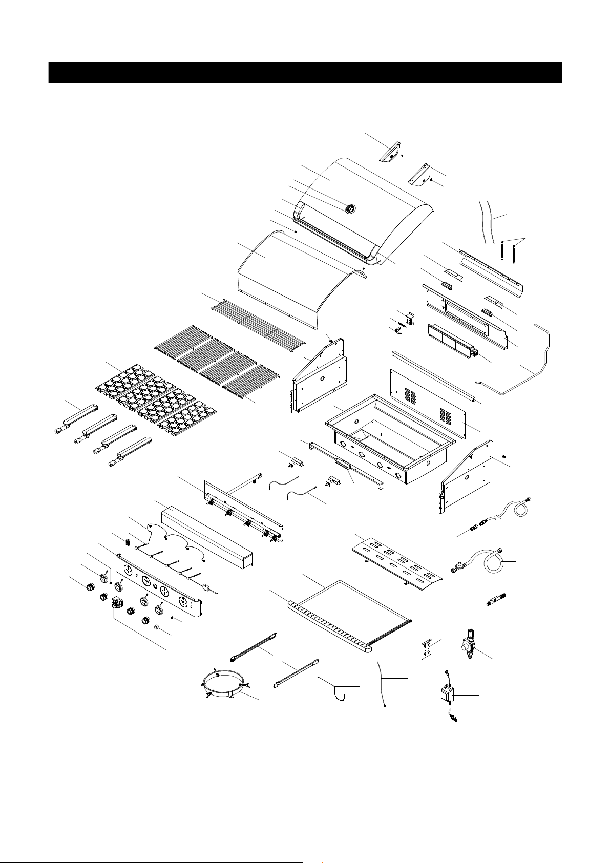
PartDiagramsand Lists............................4-14
AssemblyInstructions.................................15-18
Use&CareInstructions:
•GasSafetyand LeakTests..............19-21
•NaturalGasConnection............................22
•LightingInstructionsandLightOperation.23
•Troubleshooting...........................................24
•RotisserieInstruction.............................25-27
CleaningandMaintenance.......................28-29
CookingGuide..........................................A1-A4
FrequentlyAsked Questions..................A5-A6
Warranty...........................................Back Cover
2
Donotstoreoruse gasolineorother
flammableliquidsorvaporsinthe
vicinityofthisoranyotherappli-
ances.
AnLPcylindernotconnectedfor
use shall notbestoredinthevicinity
ofthisoranyotherappliance.
1.
2.
•LPGmodelsmustbeusedwithLiquidPropane
Gas and theregulatorassemblysupplied.Natural
Gas modelsmustbeusedwithNaturalGas only.
Anyattempttoconvert thegrill fromonefueltype
toanotherisextremelyhazardousand will voidthe
warranty.
Keepgas regulatorhose awayfromhotgrill sur-
faces and dripping grease.Avoidunnecessarytwist-
ing ofhose.Visuallyinspecthose priortoeach use
forcuts,cracks,excessivewearorotherdamage.
Ifthehose appearsdamageddo notuse thegas
grill.Call 1-800-474-5587 foracertifiedreplace-
menthose.
CaliforniaProposition 65
Combustionbyproductsproduced when using this
productcontainchemicalsknowntotheStateofCali-
forniatocause cancer, birthdefects,orotherreproduc-
tiveharm.
Brass componentson thegrill,such as hose fittings,
propanecylindervalves (soldseparately)and burner
valvestems,containleadwhich isknowntotheState
ofCaliforniatocause cancer, birthdefects,orother
reproductive harm.
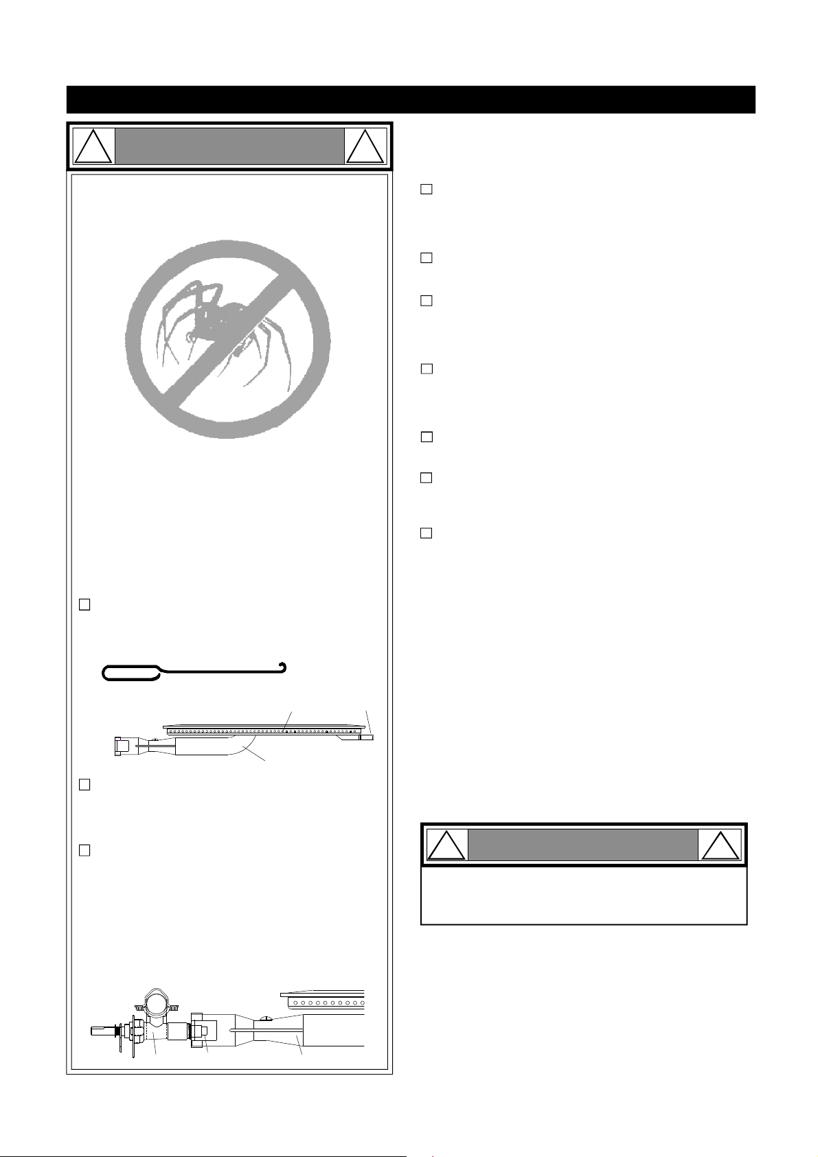
Neveruse charcoal orlighterfluidinthisgas grill.
Failuretocomplywiththese instructionscouldresult
inagrease fireorexplosion thatcouldcause serious
bodilyinjury,deathorpropertydamage.
Beforeeach use ofyourgrill: InspecttheGrease Tray,
Grease TrayHeatShieldand insideof theGrill Bowlto
besurethereisno excessivegreaseanddebris
buildup.CleantheGrease Tray,Grease TrayHeat
Shieldand insideoftheGrill Bowlfrequentlytoelimi-
nategrease/debrisbuild-upandtopreventgrease
fires. Failuretocomplywiththese instructions could
result inagrease fireand even asubsequentexplo-
sion thatcouldcause serious bodilyinjury,deathor
propertydamage.
•
•
•
•
!
Thisappliance,when installed,mustbe electri-
callygrounded inaccordancewithlocalcodes
or,inthe absenceoflocalcodes,withthe
National Electrical Code,ANSI/NFPA 70, orthe
Canadian Electrical Code,CSA C22.1.
Keep anyelectricalsupplycordand the fuel
supplyhoseawayfromanyheated surfaces.
•
•
WARNING !
DANGER
!!
1.
2.
3.
4.
Ifyousmell gas:
Shutoff gas totheappliance.
Extinguishanyopenflame.
Openlid.
Ifodorcontinues,keepawayfrom
theappliance andimmediatelycall
yourgas supplieroryourfire
department.
WARNING
! !
WARNING
! !
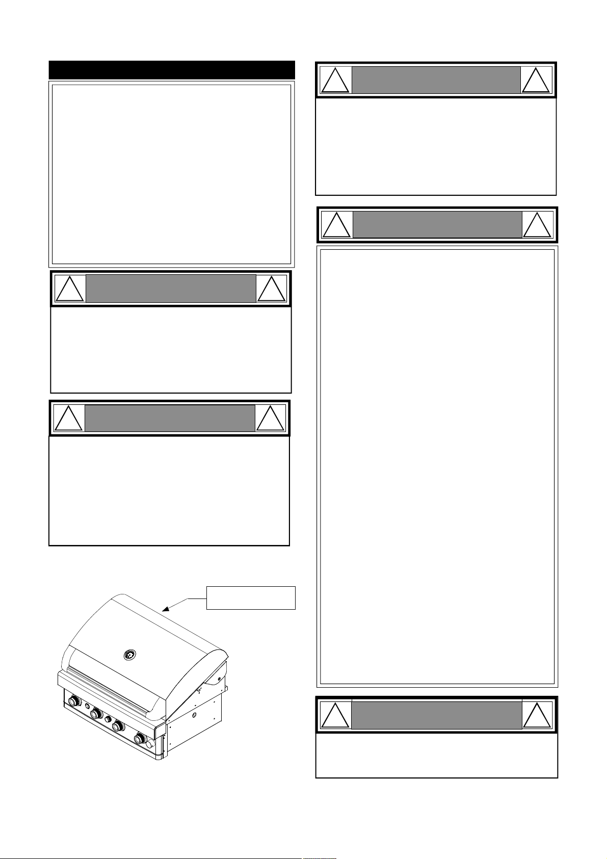
CSA labellocatedon
thebowlrearpanel.
Never coverorwraptheCooking Grids,bottom
oftheGrill Bowl,Grease Traywithaluminumfoil
oranyothermaterialthatwill absorbgrease.
! !
WARNING