TURBO ELITE BTE2616ALP User manual

Manual # P80151147B - Date:2017/07/28
Failure tocomplywith theseinstructionscould
resultin afire or explosion that could cause
seriousbodilyinjury,deathorpropertydamage.
Whetherthisgrillwasassembled byyouor
someoneelse, youmustread thisentire manual
before using yourgrillto ensure thegrillis
properly assembled, installed and maintained.
Use yourgrillat least 3 feetaway fromany
wall or surface. Use your grillat least 3feet
away fromcombustibleobjectsthatcanmeltor
catch fire such as vinyl or wood siding, fences
andoverhangsorsourcesof ignition including
pilotlightsonwaterheatersand liveelectrical
appliances.
THISGAS APPLIANCEIS DESIGNEDFOR
OUTDOORUSEONLY.
Never useyour gasgrillinagarage, porch,
shed, breezewayor anyotherenclosed area.
Never obstructthe flowofventilationair
aroundyourgasgrill housing.
Never disconnectthe gas regulator or anygas
fittingwhileyour grill islit. Alit grillcan ignite
leaking gas andcauseafire or explosion which
could result inproperty damage, personal injury
or death.
Ÿ
Ÿ
Ÿ
Ÿ
Ÿ
Ÿ
WARNING
! !
Ÿ
Grill Information Center:
Ÿ
Ÿ
NOTETO ASSEMBLER/INSTALLER:
Leave this manual withthe consumer.
NOTETOCONSUMER:
Keepthis manualforfuturereference.
RECORDYOURSERIAL#
__________________
(see silverCSA label on mainbodyof grill)
IMPORTANT:
Ÿ
FREEHELP
FROMTHE GRILLEXPERTS
BarbequesGaloreis the expert on this
product and trained to help you with:
visit www.grandhall.com or call:
1-800-474-5587
Monday-Friday8:00am-4:30pmPST
AssemblyQuestions
Grill Operation
Replacement ofDamaged or Missing parts
Ÿ
Ÿ
Ÿ
LiquidPropaneGas(LPG)Grill
ModelsBTE2616(A,B)LP,BTE3216(A,B)LP&BTE3816BLP
NaturalGas(NG)Grill
ModelsBTE2616(A,B)NG,BTE3216(A,B)NG&BTE3816BNG
BTE3216BLP/NG BTE3816BLP/NG
Operator'sManual
BTE3216ALP/NGBTE2616ALP/NG
BTE2616BLP/NG
(BTE2616B+UN2616ACT) (BTE3216B+UN3216ACT)

Table of Contents
PrimarySafetyWarnings............................1-3
Pre-AssemblyInstructions...............................3
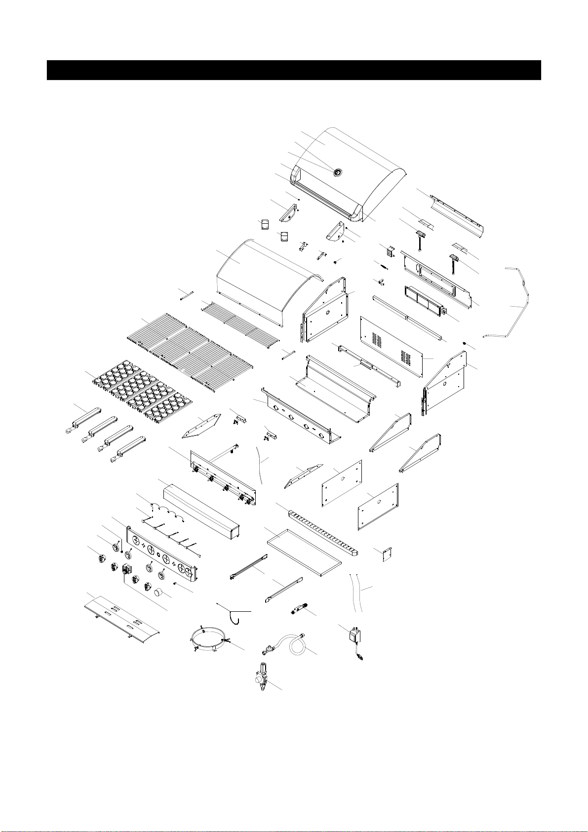
PartDiagramsand Lists............................5-13
AssemblyInstructions.................................15-18
Use &Care Instructions:
Gas Safetyand LeakTests..............19-21
NaturalGasConnection............................22
LightingInstructions andLight Operation.23
Troubleshooting...........................................24
Rotisserie Instruction..............................25-27
CleaningandMaintenance........................28-29
CookingGuide............................................A1-A4
FrequentlyAsked Questions...................A5-A6
Warranty...........................................BackCover
2
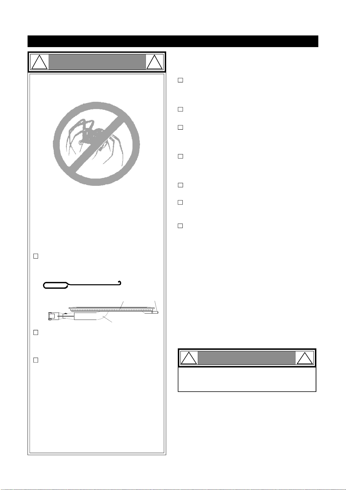
Donot storeorusegasolineor other
flammableliquids orvapors in the
vicinityof this or anyother
appliances.
AnLPcylindernotconnectedfor
use shall not bestoredin thevicinity
ofthis oranyotherappliance.
1.
2.
LPG models must be usedwith Liquid Propane
Gas and the regulatorassemblysupplied. Natural
Gasmodelsmustbe used with Natural Gas only.
Anyattempt to convert the grillfromone fuel type
toanotherisextremely hazardousandwillvoidthe
warranty.
Keepgasregulatorhoseawayfromhotgrill sur-
faces anddripping grease.Avoid unnecessarytwist-
ingof hose.Visuallyinspect hose priortoeachuse
for cuts,cracks, excessivewear or otherdamage.
Ifthe hose appearsdamageddonotusethegas
grill.Call 1-800-474-5587 foracertifiedreplace-
menthose.
CaliforniaProposition65
Combustionbyproductsproducedwhen usingthis
product contain chemicals known tothe State of Cali-
fornia to cause cancer, birthdefects,orotherreproduc-
tive harm.
Brass components onthe grill,such ashose fittings,
propane cylinder valves (sold separately) and burner
valvestems, contain lead which is knownto the State
of Californiatocause cancer,birth defects, orother
reproductive harm.
Neveruse charcoal or lighter fluid in this gas grill.
Failure to comply with these instructionscouldresult
in a grease fire or explosion that couldcause serious
bodilyinjury, deathor propertydamage.
Beforeeachuseofyourgrill: InspecttheGreaseTray,
GreaseTray HeatShieldand inside ofthe GrillBowl to
besurethereisnoexcessive greaseanddebris
buildup. Clean the Grease Tray,Grease TrayHeat
Shield and inside ofthe Grill Bowlfrequentlyto elimi-
nategrease/debrisbuild-upandtopreventgrease
fires. Failuretocomplywiththeseinstructionscould
result inagrease fire andeven asubsequent explo-
sionthat could cause serious bodily injury,death or
propertydamage.
!
Thisappliance, wheninstalled,mustbeelectri-
callygrounded inaccordancewith localcodes
or,in the absence oflocal codes, with the
NationalElectricalCode,ANSI/NFPA 70, orthe
Canadian Electrical Code, CSA C22.1.
Keepanyelectrical supplycord and the fuel
supplyhoseawayfromanyheatedsurfaces.
WARNING !
DANGER
!!
1.
2.
3.
4.
If you smell gas:
Shutoffgastotheappliance.
Extinguish anyopenflame.
Openlid.
If odor continues, keep awayfrom
theapplianceandimmediatelycall
your gas supplieroryourfire
department.
WARNING
! !
WARNING
! !
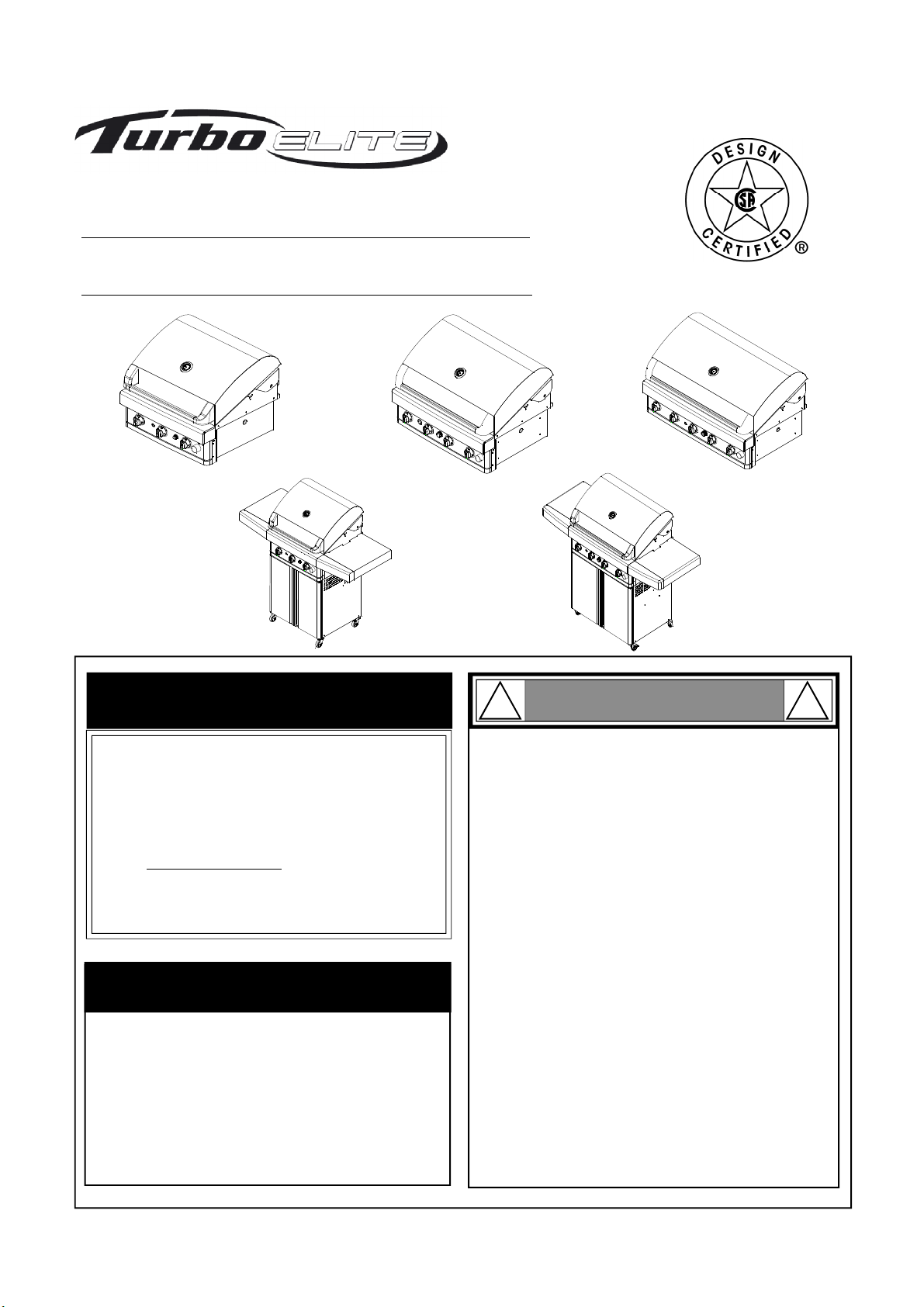
CSA label located on
thebowl rear panel.
Never coverorwraptheCookingGrids,bottomof
theGrillBowl,GreaseTraywithaluminum foilor
anyother materialthatwillabsorb grease.
! !
WARNING

Pre-AssemblyInstructions ForYour Safety
WARNING
CAUTION
! !
Failuretocomplywiththeseinstructionsmayresult
in ahazardous situation which, if not avoided, may
resultininjury.
METHOD1:Bendastiffwireorwirecoathanger
into asmallhook as shown and runthehook
throughtheBurnerTubeandinsidethe Burner
severaltimestoremovedebris.
METHOD 2: Use abottle brush withaflexible
handleandrunthebrushthroughthe Burner
Tubeand insidethe Burner severaltimesto
removeanydebris.
METHOD3: Use an air hoseto force air through
eachBurner Tube.The forcedairshould pass
debrisor obstructionsthrough the Burner and out
the Ports.
TOCLEANBURNERTUBE,
INSERTHOOK
HERE
Burner Tube
9
3
Burner Port Foot
1.
2.
3.
4. Refertothe figurebelowandperformoneofthese
3cleaningmethods:
Carefully lift each Burner upandawayfrom theGas
ValveOrifice.
Check and clean Burner/Venturi Tubesfor insects
and insect nests. Aclogged tube can lead to afire
beneath thegrill.
Spiders and small insects can spin webs and nest
inthegrillBurnerTubesduringtransitandware-
housingwhichcanleadtoagasflowobstruction
resultingin afire in andaround the Burner Tubes.
Thistype of"FLASHBACK FIRE" can cause serious
grill damageandcreate an unsafeoperating con-
ditionfortheuser.
Toreduce thechance of FLASHBACK FIRE
you must cleanthe Burner Tubes as follows
beforeinitial use. Alsodothisatleastoncea
monthin summer and fallor whenever spidersare
active inyour area,andif yourgrill hasnotbeen
used for an extendedperiodoftime.
Removethescrewsfromthe rearofeachMain Burner
usingaPhillipshead screwdriverorwrench.
WARNING: Greasecangetveryhot.AlwayshandletheGrease
Traywith aflameretardant BBQ mitt.Before removingthe
Tray,alwaysbesurethatthe grillhas properlycooled.Be
aware that the Traydoes contain grease and be extremely
careful whenremovingthe Tray to prevent spillage. Failure to
followthese instructions couldcauseseriousbodilyinjury or
property damage.
Grill InstallationCodes
Theinstallation must conformwith localcodesor,in the
absenceoflocalcodes,witheitherthe NationalFuel Gas
Code, ANSI Z223.1/NFPA54,NaturalGasand Propane
Installation Code,CSAB149.1, orPropaneStorage and
HandlingCode, B149.2.
PRE-ASSEMBLY
Readandperformthefollowingpre-assemblyinstruc-
tions:
ToolsRequiredforAssembly:
protective workgloves
protective eyewear
You will need assistance from another person tohandle
the grill headandotherlarge, heavyparts.
Open lidof shipping carton. Removetop sheet of
cardboard andpackingmaterials.Lay cardboardsheet
on floorand use as awork surfaceto protect floor and
grill parts fromscratches.
Youmayslice the cartonfront corners with autilityknife
tolay openthecartonfrontpanel.Thisallows youto
raisethe Lidandremovethecomponentspacked inside,
making iteasier to lift.
Use theHardwareand Part Diagrams to ensure allitems
are includedand freeof damage.
Do not throw awaythe bags ofhardware that are in-
cluded with boxed parts. These are required for assem-
bly.
Do not assembleor operate the grillifit appears
damaged. Iftherearedamagedor missingpartswhen
you unpack theshippingboxor youhavequestionsdur-
ingthe assembly processcall 1-800-474-5587 M-F 8AM-
4:30PMPSTfor assistance.
CAUTION !
Whenusingelectrical appliances, basic safety
precautions should alwaysbe used.
!
Phillips headscrewdriver

4
*One AA Battery included in theHardwarePack
HardwareDiagramforModelsBTE2616BLP/NG&BTE3216BLP/NG&BTE3816BLP/NG
Hardware PartsList for ModelsBTE2616BLP/NG&BTE3216BLP/NG&BTE3816BLP/NG
PanHeadScrew3/16"x3/8"
Part #S182G03061
Qty.7(ForModelsBTE2616BLP,BTE3216BLP, BTE3816BLP)
Qty.2(ForModels BTE2616BNG, BTE3216BNG &BTE3816BNG)
PART# PART DESCRIPTION QTY PURPOSEOFPART
P06013018CHardwarePack 1 Foruseinassemblyof ModelsBTE2616B, BTE3216B, BTE3816B
S182G03061PanHeadScrew3/16"x3/8" 2 Install theTransformerBracket (BTE2616B, BTE3216B, BTE3816B)
S182G03061PanHeadScrew3/16"x3/8" 2 Install theBracket withLPRegulator(LPGModel Only)
S182G03061PanHeadScrew3/16"x3/8" 3 Install theTankTraySet ontotheBottomPanel(LPGModel Only)
S313G0306BAABattery 1

Parts Diagram for Models BTE2616BLP&BTE2616BNG
5
1
2a
3
56
13
15
4
7
86
9
9
32
27
20
16
18
28
17
26
14
14
10 10 11 12
19
21
22
23
24
25
31
29
30
41
46
47
50
40
44
39
38
43 42
48
49
45
37 35 36
34
33
37
53 52
55
51
54
2b
58
56 57

PartsList forModelsBTE2616BLP&BTE2616BNG
6
KEY DESCRIPTION PART# QTY.
1Lid Assembly P0014644AA 1
2a TemperatureGauge P00601551A 1
2b TemperatureGauge Seat P00614031A 1
3 LidHandleBracket,Left P00307052E 1
4 LidHandleBracket,Right P00308052E 1
5 LidHandle P00215041H 1
6ProtectivePad P05518002I 4
7 LidAssemblyBracket,Left P03320007C 1
8 LidAssemblyBracket,Right P03320008C 1
9 LidHingewithNut P05501136L 2
10 LidTrimPlateBracket P03318007A 2
11 LidAssemblyReinforcingBracket, Left P033180084 1
12 LidAssemblyReinforcing Bracket, Right P033180094 1
13 LidTrimPlate P0011464A4 1
14 WarmingRackBracket P01529002J 2
15 Warming Rack P01514023B 1
16 Cooking Grid P016060404 2
17 FlameTamerwithCeramic P01720041A 3
18 Burner/Main P02001070B 3
BackBurnerCover(LPG) P06906107C 1
BackBurnerCover(NG) P06906108C 1
20 TrimPanel,Rear P07515030A 1
21 BowlSide Panel, Rear/Upper P0075822BC 1
22 BackBurnerThermocoupleProtector P03328050C 1
23 Thermocouple forBackBurner P05305072B 1
24 BackBurnerElectrode P02614071C 1
BackBurnerAssembly(LPG) Y0030028 1
BackBurnerAssembly(NG) Y0030029 1
26 BackBurnerExtension Tube P03701011A 1
27 BowlSide Panel, Rear/Lower P0073756FC 1
28 BurnerBracket P02208047A 1
29 BowlRearPanelAssembly P0077201B4 1
30 BowlFront Panel P0076315BC 1
31 BowlSide Panel,Left P007613564 1
32 BowlSide Panel,Right P007623464 1
33 BowlSide TrimPlate,Left / Upper P0077301R4 1
34 BowlSide TrimPlate,Right/ Upper P0077401R4 1
35 BowlSide TrimPlate,Left / Lower P0077501R4 1
36 BowlSide TrimPlate,Right/ Lower P0077601R4 1
37 GreaseShield P069021414 2
38 ElectricWiresSet P02615203A 1
39 GasCollectorBoxwithElectrode P02608061A 2
19
25

PartsList forModelsBTE2616BLP&BTE2616BNG
7
KEY DESCRIPTION PART# QTY.
GasValve/ManifoldAssembly(LPG) Y0060840 1
GasValve/Manifold Assembly(NG) Y0060841 1
41 Bowl Front TrimPlateAssembly P02917011S 1
42 ElectricWiresSet P02627024A 1
43 LEDRectifierwithWireAssembly P05383020B 1
44 Control Panel P02917043S 1
45 SwitchforLight P05360004B 1
46 Control Knob SeatwithLEDlight P03445014A 3
47 ControlKnob forMain Burner P03446024A 3
48 LEDLight forBackBurner P05373011B 1
49 Control KnobforBackBurner P03418245U 1
50 ElectricIgnitor-4Ports P02505014G 1
51 GreaseTrayHeat Shield P06904064C 1
52 GreaseTrayHandle P0272017CC 1
53 GreaseTray P02717923C 1
54 GreaseTraySlide Set P05516140M 1
55 LightingStick P05507140M 1
56 TransformerBracket P03328057A 1
57 TransformerWireSet P05352027B 1
58 Transformer P05374021B 1
59 RegulatorHoseConnector(LPG) P03901056C 1
60 RegulatorwithHose(LPG) P03635005A 1
61 RegulatorwithConnector(NG) P03614005C 1
62 TankTraySet(LPG) Y0340055 1
Rotisserie Assembly Y0250219 1
HardwarePack P06013018C 1
Operator'sManual P80151147B 1
40

Parts Diagram for Models BTE3216BLP&BTE3216BNG
8
16
18 36
13
29
30
32
33
34
41a
41b
63
62
64
19
20
21
23
24
25
2b
43
52
26 27
46
31
42
51
65
48
53
21
20
55
28
17
3
2a
5
45
4
58
5049
47
44
54
1
56
57
35
15 22
6
7
86
9
9
14
14
10 10 11 12
40
39
38
37
40
61
59
60

PartsList forModelsBTE3216BLP&BTE3216BNG
9
KEY DESCRIPTION PART# QTY.
1LidAssembly P0014759AA 1
2a TemperatureGauge P00601551A 1
2b TemperatureGaugeSeat P00614031A 1
3 LidHandleBracket, Left P00307052E 1
4 LidHandleBracket, Right P00308052E 1
5 LidHandle P00215039H 1
6ProtectivePad P05518002I 4
7 LidAssemblyBracket, Left P03320007C 1
8LidAssemblyBracket,Right P03320008C 1
9LidHingewithNut P05501136L 2
10 LidTrimPlateBracket P03318007A 2
11 LidAssemblyReinforcingBracket,Left P003180084 1
12 LidAssemblyReinforcing Bracket, Right P033180094 1
13 LidTrimPlate P0011465A4 1
14 WarmingRackBracket P01529002J 2
15 WarmingRack P01515032B 1
16 CookingGrid P01606041B 4
17 FlameTamerwithCeramic P01720041A 4
18 Burner/Main P02001070B 4
BackBurnerCover(LPG) P06906107C 1
BackBurnerCover(NG) P06906108C 1
20 LampCover P05352013E 2
21 LampAssembly P05352028B 2
22 BackBurnerFrame P02011078B 1
23 BackBurnerThermocoupleProtector P03328050C 1
24 ThermocoupleforBackBurner P05305072B 1
25 BackBurnerElectrode P02614071C 1
BackBurnerAssembly(LPG) Y0030028 1
BackBurnerAssembly(NG) Y0030029 1
27 BackBurnerExtensionTube P03701011A 1
28 TrimPanel,Rear P07515027A 1
29 BowlSidePanel, Rear/Lower P0073757BC 1
30 BurnerBracket P02204357A 1
31 CrosslightChannel P02212415A 1
32 BowlRearPanelassembly P0077701B4 1
33 BowlFront Panel P0076316BC 1
34 BowlSidePanel, Left P007613564 1
35 BowlSide Panel,Right P007623464 1
36 BowlSideTrimPlate, Left /Upper P0077301R4 1
37 BowlSideTrimPlate, Right/ Upper P0077401R4 1
38 BowlSideTrimPlate, Left /Lower P0077501R4 1
39 BowlSideTrimPlate, Right/ Lower P0077601R4 1
40 GreaseShield P069021414 2
26
19

10
PartsList forModelsBTE3216BLP&BTE3216BNG
KEY DESCRIPTION PART# QTY.
41a GasCollectorBoxwithElectrode P02608059C 1
41b GasCollectorBoxwithElectrode P02608060A 1
42 ElectricWiresSet/Electrode P02615204A 1
GasValve/Manifold Assembly(LPG) Y0060842 1
GasValve/Manifold Assembly(NG) Y0060843 1
44 Bowl Front TrimPlateAssembly P02915781S 1
45 ElectricWiresSet P02627025A 1
46 LEDRectifierwithWireAssembly P05383021B 1
47 Control Panel P02915993S 1
48 SwitchforLamp P05360003B 1
49 Control Knob Seat withLEDLight P03445014A 4
50 Control KnobforMain Burner P03446024A 4
51 LEDLightforBackBurner P05373011B 1
52 Control Knob forBack Burner P03418245U 1
53 ElectricIgnitor, 4-Port P02505014G 1
54 GreaseTrayHeat Shield P06904065C 1
55 GreaseTrayHandle P0272018CC 1
56 GreaseTray P02717933C 1
57 GreaseTraySlideSet P05516140M 1
58 Lighting Stick P05507140M 1
59 TransformerBracket P03328057A 1
60 TransformerWireSet P05352029B 1
61 Transformer P05374021B 1
62 RegulatorHoseConnector(LPG) P03901056C 1
63 RegulatorwithHose(LPG) P03635005A 1
64 RegulatorwithConnector(NG) P03614005C 1
65 TankTraySet (LPG) Y0340055 1
Rotisserie Assembly Y0250220 1
HarewarePack P06013018C 1
Operator'sManual P80151147B 1
43

Parts Diagram for ModelBTE3816BLP&BTE3816BNG
11
63
57
64
58
9
3
5
4
6
7
8
40
41
43
42
44
48
46
47
52
56
28
59
20
25
26
27 24
19
20
62
61
1
2a
2b
10 10 11
12
13
14
14
16
17
29
22
23
18
21
21
9
34
33
30
31
36
35
32
37 38
39
39
45
60
53
50
51
49 54
55
15

PartsListforModel BTE3816BLP&BTE3816BNG
12
KEY DESCRIPTION PART# QTY.
1LidAssembly P0014807AA 1
2a TemperatureGauge P00601551A 1
2b TemperatureGaugeSeat P00614031A 1
3 LidHandleBracket,Left P00307052E 1
4 LidHandleBracket, Right P00308052E 1
5 LidHandle P00215040H 1
6ProtectivePad P05518002I 4
7 LidAssemblyBracket,Left P03320007C 1
8 LidAssemblyBracket, Right P03320008C 1
9 LidHingewithNut P05501136L 2
10 LidTrimPlateBracket P03318007A 2
11 LidAssemblyReinforcing Bracket, Left P033180084 1
12 LidAssemblyReinforcingBracket, Right P033180094 1
13 LidTrimPlate P0011466A4 1
14 WarmingRackBracket P01529002J 2
15 Warming Rack P01517008B 1
16 Cooking Grid P01606401B 5
17 FlameTamerwithCeramic P01720041A 5
18 Burner P02001070B 5
BackBurnerCover(LPG) P06906107C 1
BackBurnerCover(NG) P06906108C 1
20 LampCover P05352013E 2
21 LampAssembly P05352028B 2
22 BackBurnerFrame P02011081B 1
BackBurnerAssembly(LPG) Y0030028 1
BackBurnerAssembly(NG) Y0030029 1
24 BackBurnerExtension Tube P03701011A 1
25 ThermocoupleforBackBurner P05305072B 1
26 BackBurnerElectrode P02614072C 1
27 ThermocoupleProtector P03328050C 1
28 TrimPanel, Rear P07515028R 1
29 BowlSidePanel, Rear/Lower P0073758BC 1
30 BurnerBracket P02210057A 1
31 BowlRearPanelassembly P0077801B4 1
32 BowlFrontPanel P0076317BC 1
33 BowlSide Panel,Left P007613564 1
34 BowlSide Panel,Right P007623464 1
35 BowlSideTrimPlate, Left / Upper P0077301R4 1
36 BowlSideTrimPlate, Right/ Upper P0077401R4 1
37 BowlSideTrimPlate, Left / Lower P0077501R4 1
38 BowlSideTrimPlate, Right/ Lower P0077601R4 1
39 GreaseShield P069021414 2
40 GasCollectorBoxwithElectrode P02608061A 4
41 ElectricWiresSet/Electrode P02615206A 1
GasValve/ManifoldAssembly(LPG) Y0060844 1
19
23
GasValve/Manifold Assembly(NG) Y0060845 1
42

PartsListforModel BTE3816BLP&BTE3816BNG
Important: Use only Barbeques Galore's replacement parts.Theuse ofanypartthatisnotBarbeques Galore's replacement
partcanbedangerousand will alsovoidyourproductwarranty. KeepthisOperator'sManualfor convenientreferraland
forpartreplacement.
For the repair or replacement partsyou need:
Call 1-800-474-5587 M-F8AM-4:30PMPST
Toobtain thecorrectreplacementpartsforyourgasgrill,pleaserefer to the partnumbersinthispartslist. The
following informationisrequiredto ensureyou receivethecorrectparts:
1.ModelandSerialNumber (see CSAlabel ongrill)
2. Part Number
3. Part Description
4.Quantityofpartsneeded
13
KEY DESCRIPTION PART# QTY.
43 Bowl Front TrimPlateAssembly P02916061S 1
44 ElectricWiresSet P02627026A 1
45 LEDRectifierwithWireAssembly P05383022B 1
46 Control Panel P02916163S 1
47 SwitchforLamp P05360003B 1
48 ControlKnobSeatwithLEDLight P03445014A 5
49 ControlKnobforMain Burner P03446024A 5
50 LEDLight forBackBurner P05373011B 1
51 ControlKnobforBackBurner P03418245U 1
52 ElectricIgnitor,6-Port P02505025G 1
53 GreaseTrayHeatShield P06904066C 2
54 GreaseTrayHandle P0272019CC 1
55 GreaseTray P02717943C 1
56 GreaseTraySlide Set P05516140M 1
57 LightingStick P05507140M 1
58 TransformerBracket P03328057A 1
59 TransformerWireSet P05352030B 1
60 Transformer P05374021B 1
61 RegulatorHoseConnector(LPG) P03901056C 1
62 RegulatorwithHose(LPG) P03635005A 1
63 RegulatorwithHose(NG) P03614005C 1
64 TankTraySet (LPG) Y0340055 1
RotisserieAssembly Y0250221 1
HardwarePack P06013018C 1
Operator'sManual P080151147B 1

KEY
1.
2.
3.
4.
5.
6.
7.
8.
PART#
DESCRIPTION QTY
1
3
1
1
1
2
1
1
2
2
14
CustomerServiceHelpline:Ifyou havequestionsaboutassemblyorgrilloperation, orif therearedamagedor
missing partswhenyouunpackthisunitfromtheshippingbox, callus8:00 am-4:30 pmPST,Mondaythrough
Fridayat1-800-474-5587
Hardware forRotisserie
Rot.Collar
Rot.Thumbscrew1/4"x1/2"
Rot. Spit(for BTE2616(A,B)LP/NG Models)
Rot. Spit(for BTE3216(A,B)LP/NG Models)
Rot. Spit (for BTE3816BLP/NG Models)
Rot.HoldingFork
Rot. MotorBracket
Rot. Motor/AC
Rot. PhillipsHeadScrew3/16"x1/2" UNC
Rot. Washer 3/16"
P05508254A
S196G04081
P05508253A
P05508230A
P05508231A
P055082125
P03308029C
P07101039B
S112G03081
S411G03061
Rotisserie Screw
3/16"x1/2"UNC
Qty.2
Part #S112G03081
RotisserieWasher
3/16"
Qty.2
Part #S411G03061
RotisserieThumbscrew
1/4"x1/2"
Qty.3
Part #S196G04081
Rotisserie AssemblyParts Diagramfor BTE2616(A,B)LP/NG, BTE3216(A,B)LP/NG &BTE3816BLP/NG
Rotisserie AssemblyPartsList forBTE2616(A,B)LP/NG,BTE3216(A,B)LP/NG &BTE3816BLP/NG
1
2
2442
3
6
8
5
7

InstallationInstructionsforModelsBTE2616BLP/NG,BTE3216BLP/NG&BTE3816BLP/NG
CAUTION: Even though it ispossible for one person to install this grill, it is better toobtainassistance fromanother
personwhenhandlingthelarge,heavypieces.
1InstallGrill Head
Haveyourassistanttohelpyouliftthegrillupand placeitintothecutoutofyourisland(SeeDiagram)
The island shownin the diagramis for illustrationpurposeonly.It is not in scale.
15
The leftcabinet is for agas
tank
InstallTransformer. Connect theTransformerto Power Source.
2Installthetransformer bracket ontotheunderside of the rightbowlpanelusing 2Pan Head Screws
3/16"x3/8" andtightensecurely(See Fig.1).
PanHeadScrew
3/16"x3/8"
Qty.2
Part#S182G03061
Transformer Bracket
Note:Thegrill head you purchased isto be installedonthe island whichis not includedin thispurchase. You either
needto purchaseaprebuilt islandor youhavetobuild your ownisland.Beforebuilding yourgrillisland, please read
theconstruction guidelines and clearancesin Fig.6 and on pages 16 &17 carefully.
RightBowl
Panel
Transformer
plug
Wire
Transformer
socket
AC-plug
Fig.1
Fig.2
Fig.3
Attach transformertothetransformer bracketby insertingthefourstudbolts onthetransformerintothe
fourkeyholesonthetransformerbracket.Pressthetransformerdownwarduntilitrestsfirmly inplace.
(See Fig. 2)
Insert the transformer-plug into the transformer-socket and tighten securely.(See Fig.3)
Depending on your islandconstruction,youmayneedtomakeonehole onyour islandrearpanel.Then
pullthetransformercordoutthroughtheholeand plug itintoaproperly grounded120VACoutlet.
NOTE: Incasenature gasfrom the houseisused,pleasecontinuetostep3.If thegas tank is used,please
skip step 3and go directlyto step 4.

3InstallNatural Gas(NG)Regulator and12 FootHose
Connect theNGregulatortotheinletofgasmanifold. (SeeFig.4)
Connecttheswivelnutofthe12ft.NGhose totheverticalfittingoftheNGRegulator.
WHEN YOU FINISHED THISSTEP, PLEASE SKIP TOSTEP 6.
NOTE: Makesurethe12ft.NGhosestaysawayfromsharpedges.
Gas Manifold
NGRegulator
SwivelNut
of 12' Hose
Verticalfitting
Fig.4
InstallRegulator, TankTray Set and Liquid Propane(LP)GasTank
4
Pan Head Screw
3/16"x3/8"
Qty. 5
Part #S182G03061
Island Bottom Panel
LPGasTank
Fig.5
Regulator hose connector
5/8" UNF male thread
Clamp (Not provided)
Stainless Steel Flexible Connector(Notprovided) must
compy withthe Standard forconnectors for Outdoor Gas
Appliances andManufactured Homes, ANSI Z21.75 CSA
6.27,andsuitableforoutsideinstallation. Themaximum
lengthofthe connectionshallbe6ft.(1.82m).
On the properlocation, drill2holes ontheisland left side panel forinstalling theregulatorhoseconnector.
Theninstalltheregulatorusing2Pan HeadScrews 3/16"x3/8"andtightensecurely.
Ontheproperlocation,drill3holesonthe islandleftbottom panelfor installing thetanktrayset.Then install
tank tray setusing3PanHead Screws3/16"x3/8"andtighten securely.
Connectthestainlesssteelflexibleconnectortothemanifoldandregulator,then useaclamptoholdthe
stainlesssteelflexibleconnectorasshown forsecuring.
Placethe LPgastankintothetanktray set.Make sure thetankvalvefacing therightrearcorner ofleft island.
Tightenthe wing bolt tosecure theLP gastank.(SeeFig. 5)
ConnecttheLPregulatorontotheLPgastank.
CAUTION: Thereshall be aminimumclearance of2inches (50.8mm)between thefloor ofthe LP-gas cylinder
enclosure andthe ground.Proper ventilationmust beadded totheisland.
GasLine
NOTE: Tocomplywith the standarad,built-inapplianceforusewitharemoteself-contained LPgassupply
systemmust use rigid pipe,semi-rigid pipe or aconnector complying with the Standard for Connectorsfor
GasAppliances,ANSIZ21.24/CSA 6.10,or the StandardforConnectors forOutdoor GasAppliancesand
Manufactured Homes, ANSIZ21.75/CSA 6.27 to connect the remoteself-containedgas supplysystem.For
safety,wesuggesttouseastainlesssteelflexibleconnectorasshown.But,ifusingsemi-rigidtubing,do
notusematerials madeof aluminumoraluminum alloytubing. The connectorshouldbeinstalled atthelocation
visiblewhenopeningthedoor.
TankTraySet
16

17
5Install Partition Panel
IgnitorCap
IgnitorSlot
AA Battery
Spring
Install Ignitor Battery
RemoveIgnitorCapfromControlPanel.
Place suppliedAAbatteryinto theIgnitorSlot withpositivepolefacingyou.
Install the CapandSpring overtheAAbatteryandtighten securely.
6
PartitionPanel
(abovetheGasTank)
Fig. 6
TankTraySet
5"
22-24"
21"
1"
17-19"
5"
Vent Openingsmust
be atleast 1/8"wide
The gas grill is designed for use with amaximumof 20 lb tank. As per standard, apartition panel (not
included)or equivalent deviceisrequiredtobeinstalledinthe leftcabinetofthe islandfor preventing
theuse of 30 lb tank.
Note: Makesurethereis22~24"ofclearancebetweenthepartitionpanelandtanktrayset.Thespace
around the gas tank isnot greater than 12".
5"
+-

18
Final GrillAssemblyStep
Whenyouhave finishedassemblingyourgrill,
be surethatallscrewsare tightened for safe
operation of your grill.
Beforeeachuseofthegrill,makesurethe
Grease Trayis fullyseated under the Grill Bowl.
CAUTION:Before each useof your grill, inspect
the Grease Tray,Grease TrayHeat Shield and in-
side of the Grill Bowlto be sure there is no exces-
sive grease anddebris buildup. Clean theGrease
Tray,GreaseTrayHeat Shield andinsideofthe
GrillBowlfrequentlytoeliminategrease/debris
build-upandtopreventgrease fires.
(forModelBTE3816(A,B)LP/NG)
Spark Electrode Tip
SparkReceiver
Spark Gap3/16"
Gas Collector
Box
AA Batterymaybe installedbackwards.
Electric wires maybe loose. RemovetheAABattery
andinspecttheIgnitorJunctionBoxfoundbehind
theControl Paneland reconnectanyloose wires.
-
-
Main Burner Electrode Check with the
assistance ofanotherperson,performthis
ElectrodeCheck before proceeding.
Be sureall control knobs are set to"OFF"
and open the grilllid.
Haveyour assistant standto the right of the grill
and look toward the front of the grill bowl. Never
putyourfaceinside thegrillhead.
Push and turnburnercontrolknob to and you
will hear a"clicking" sound and your assistant
wouldsee atinyblue spark within eachgas
collector box.If asparkis present, the electrode
tips are properlypositioned.
If no spark is seen, the sparkgap needsto be
adjustedas follows:
This test will ensure that the Spark Electrode Tips
areproperlypositionedsoyourgrilllightseasily.
If thegap between the spark electrode tipand
receiverismorethan3/16" wideuseneedle nose
plierstogently squeeze the gas collector boxto
narrowgap.
Recheckthe electrode again,ifno "clicking"soundis
heard:
Rotisserie BurnerElectrode Check
Pushandturnrotisserieburnercontrolknobto.
Lookforspark betweenelectrode tip andspark
receivertip.
Ifyoudon'tseeasparkfrom therotisserieburner,
adjust the gapbetween the electrode tip and spark
receiver tip to3/16"wide.
Install CookingComponents
9Placetheflametamer with ceramicontothe lower
ledgeofthegrillbowlabovethe burners.
Place the cooking gridsontotheupper ledgeof
thegrillbowl abovetheflame tamer racks.
Placethewarmingrack ontothewarmingrack
bracketsonthegrillbowl sidepanels.
WarmingRack
CookingGrids
Flame Tamer WithCeramic
(forModelBTE2616(A,B)LP/NG)
WarmingRack
CookingGrids
Flame Tamer WithCeramic
(For BTE3216B: 4pcs)
(For BTE3816B: 5pcs)
7
8
9
(For BTE3216B:4pcs)
(For BTE3816B:5pcs)

19
USE AND CARE INSTRUCTIONS
CORRECT USEOF LPGASTANK
TheLPGas tankmustbeconstructedandmarked in
accordancewiththe SpecificationsforLP-Gas Cylinders
oftheU.S.DepartmentofTransportation(D.O.T.)orthe
National Standard of Canada, CAN/CSA-B339, Cylinders,
Spheres and Tubes for Transportation of Dangerous
Goods and Commission; as applicable.
TheLP Gastankmusthaveashutoffvalve, terminating
inanLPGassupply tankvalve outlet,thatiscompatible
with aType1tankconnectiondevice.The LPGastank
mustalsohaveasafetyreliefdevicethathasadirect
connection withthe vaporspaceofthetank.
Thetank supplysystemmust be arrangedforvapor
withdrawal.
The LPGas tank must haveacollar to protect thetank
valve.
Never connectan unregulated LP gas tankto your gas
grill.Thegasregulatorassemblysuppliedwithyourgas
grill is adjusted to haveanoutlet pressure of 11" water
column(W.C.)for connection toanLPgas tank.Only
usetheregulatorandhoseassemblysuppliedwithyour
gas grill. Replacement hose and regulator assembly
mustbe identicalto those listedin the partslistof this
Operator's Manual as specified byBarbeques Galores.
HaveyourLPGasdealer check the reliefvalve after every
filling to ensureitremainsfree of defects.
Always keepLPGastankinuprightposition.
Do not subject the LP Gas tank to excessive heat.
Neverstorean LPGastankindoors. Ifyoustore your
gasgrill in the garage alwaysdisconnect the LP Gas
tankfirstandstore itsafely outside.
LPGas tanksmustbestoredoutdoorsinawell-
ventilatedareaandoutof thereachofchildren.
Disconnected LP Gas tanks must notbe stored ina
building,garageoranyotherenclosedarea.
The regulator andhose assemblycan be seenby
opening the cabinetdoor andmust beinspected before
eachuseofthegrill.Ifthe hoseisdamagedinany way,
it must be replaced priorto using the grill again.
Anyattempt to convert the grill fromone fuel type to
anotherisextremely hazardousandwillvoidthewar-
ranty.
Neverlightyourgasgrillwiththelid closedorbefore
checking to ensurethe burnertubes are fullyseatedover
thegasvalveorifices.
Neverallow children to operateyour grill. Donot allow
childrenorpetstoplay nearyourgrill.Always supervise
childrenandpetsif theyareinthevicinity oftheunit.
Never usecharcoalorlighterfluidin this grill.
Useof alcohol,prescriptionornon-prescriptiondrugs
canimpairyourability toproperlyassembleand
safelyoperate yourgrill.
Keep fire extinguisherreadilyaccessible.Intheevent
of aoil/grease fire, donot attempt toextinguish with
water. Use type Bextinguisher orsmotherwith dirt,
sand or baking soda.
In the event of rain, turn off the burnersand gas
supply.Waitforthegrilltocool, and thenplacea
cover on it.
Useyourgrill onalevel,stablesurfaceinan area
clearof combustiblematerials.
LPGasgrillmodels aredesigned forusewithastandard
20 lb. Liquid Propane Gas (LP Gas) tank (soldsepa-
rately). Never connect your gas grill to an LPGas tank
thatexceedsthiscapacity.Atank ofapproximately12
inchesindiameter by18-1/2 inches highisthemaximum
sizeLP Gas tank to use. You must use an "OPD" gas
tankwhichoffersalisted Overfill PreventionDevice.
Thissafety feature prevents tankfrombeingoverfilled
whichcan causeamalfunction of the LP Gas tank. Do not leavegrill unattended whenin use.
Do not movethe appliance when in use.
Allowthegrill to coolbeforemovingorstoring.
Do notuse your grill as aheater.
Never use your gas grill on abalcony,deck, patio
abovetheground floorofyourhome.
This grill is not intended to be installed in or on
recreational vehicles and/or boats.
Thegrillis not intended for commercial use.
!
Do not store aspare LP-Gas tank underor near
this appliance.
Never fill the tank beyond 80 percent full; and
Ifthe informationin "(a)"and"(b)"isnotfollowed
exactly,afire causingdeathor serious injury may
occur.
A.
B.
C.
WARNING !
Refertothethistablewhendesigningthe island unit
for the BTE2616BLP/NG,BTE3216BLP/NG& BTE3816BLP/NG.
Side*andRear*showtheminimumamountofdistance
the unit must be fromcombustibles (ex.Vinylor wood
siding, fences and overhangs)or sources of ignition (ex.
Pilotlights onwaterheatersandlive electrical
appliances). Height* shows the minimumheight the
islandunit must bestarting fromthe ground up.
7"minimumclearance
fromcutout (for lid)
Side*
Depth
Height
Width
Non-combustible
Construction
Rear*
Height*
Model Height Width Depth Side* Rear*Height*
BTE2616
BLP/NG 9-1/2"24-1/2"19-3/4" 36" 36" 29"
BTE3216
BLP/NG 9-1/2"30-1/2"19-3/4" 36" 36" 29"
BTE3816
BLP/NG 9-1/2" 38" 19-3/4" 36" 36" 29"
!WARNING !

20
USE AND CARE INSTRUCTIONS
Brushsoapy solution ontoLPGastank in the ar-
eas indicated bythearrows. See diagram.
Ifgrowing bubblesappeardonotuseor move the
LP Gastank.CallanLPGas Supplieror yourFire
Department.
NOTE about LPGas Tank Exchange Programs
Many retailers that sell grills offer you the option ofre-
placing your emptyLP Gas tank throughan exchange
service. Use onlythosereputable exchange compa-
niesthat inspect,precisionfill, test andcertifytheir tanks.
Exchange yourtank only foranOPDsafety feature-
equipped tank as describedin theLPGastank section
ofthis guide.
Ÿ
Howto LeakTest your LP Gas Tank
Use a clean paintbrush and a 50/50 mildsoap and
watersolution.
Ÿ
Ÿ
Ÿ
Foryoursafety:
Leak test newand exchanged LPGas tanks BEFORE
connecting one to yourgrill.
Always keepnewand exchangedLPGas tanksinan
uprightpositionduringuse,transit orstorage.
All leak tests must be repeated each timeyour LPGas
tank is exchangedor refilled.
When checking for gas leaks do not smoke.
Donotuseanopen flameto check for gas leaks.
Your grill mustbe leak tested outdoors in a well-ven-
tilated area, awayfrom ignition sources such as gas
fired orelectrical appliances. Duringtheleaktest, keep
your grill awayfromopen flames or sparks.
Do not use household cleaning agents. Damageto
gasassemblycomponents can result.
Ÿ
Ÿ
Ÿ
Ÿ
Ifgrowing bubblesappeardonotuseor move the
LP Gas tank.ContactanLP Gas Supplier or your
fire department!
WARNING
!!
Securea20lbLP Gas TanktoGasGrill
(for BTE2616
(A,B)
LP, BTE3216
(A,B)
LP &BTE3816BLP)
NOTE: WhenusingLiquid Propane,EXTREMECAU-
TION should be used to provide ampleventilation of
vaporfromtheenclosure. LPGas vaporisheavier
than air andSERIOUSINJURYfromaDANGEROUS
EXPLOSIONcouldoccurifLPGasisallowed to
accumulate inan enclosure and thenignited. Boththe
Barbecueenclosure and LPcylinderenclosure re-
quireventing thatmust be provided atthe floor level
oftheenclosuretoallow anyleakingLPGas vapor
to escape(seeFig. 1).
NOTE: When installingabarbecue equipped for liquid
propane(LP) in an island, the propane tank must be
inaseparateenclosure thatiscompletely isolated
fromthebarbecue.Itmustbecross-ventilatedin
accordancewiththe current standards. Thepropane
tank MUSTNEVER be installed directlyunder the
barbecue.
NOTE: The total ofthe upperventilation openings
mustbe aminimumof20 sq. inches.The totalof
thelower ventilationopenings mustbeaminimum
of10sq.inches. Upper andlowerventilation open-
ingsMUST BEPROVIDEDonbothsides ofbuilt-in
construction. The top of the upper ventilation openings
must belocated within 5" fromthe topof the island.
Thebottom ofthelowerventilationopeningsmustbe
at least1" or less fromthe floor oftheisland. The
topofthelower ventilationopenings cannot bemore
than 5"fromthe floor of the island. Everyventilation
opening mustbeaminimumof1/8".(See Fig.6on
page 17). Please ask Barbeques Galore's associate
formoredetails.
LPGasModelonly:
Note:Youcanonlyusea20lbLPGas Tank in thisGas
Grill.
Fig.1
5/8"UNFMale
Thread
AirVents
CSAApproved Stainless
Steel Flexible Connector
AirVents
Non-Combustible
Construction,suchas
stone, marble, cement
Clampdown
flexline
Thebuilt-in applianceforuse witha remote self-contained LP
Gassupply systemmust use rigid pipe, semi-rigidtubingor a
connectorcomplying withtheStandardforConnections for
GasAppliances,ANSI Z21.24/CSA6.10, orthestandard for
ConnectorsOutdoor GasAppliance and Manufactured Homes,
ANSI21.75/CSA6.27andsuitable foroutsideinstallation.The
maximumlengthof the connection shall be 6 ft(1.82m).
The connector should be installedat the location visible
whenopening the door.
The connector must be awayfromanysharp points or sharp
edges.
When using semi-rigid tubing,do not use materials madeof
aluminiumor aluminiumalloy.
Note:
This manual suits for next models
10
Table of contents
Other TURBO ELITE Grill manuals