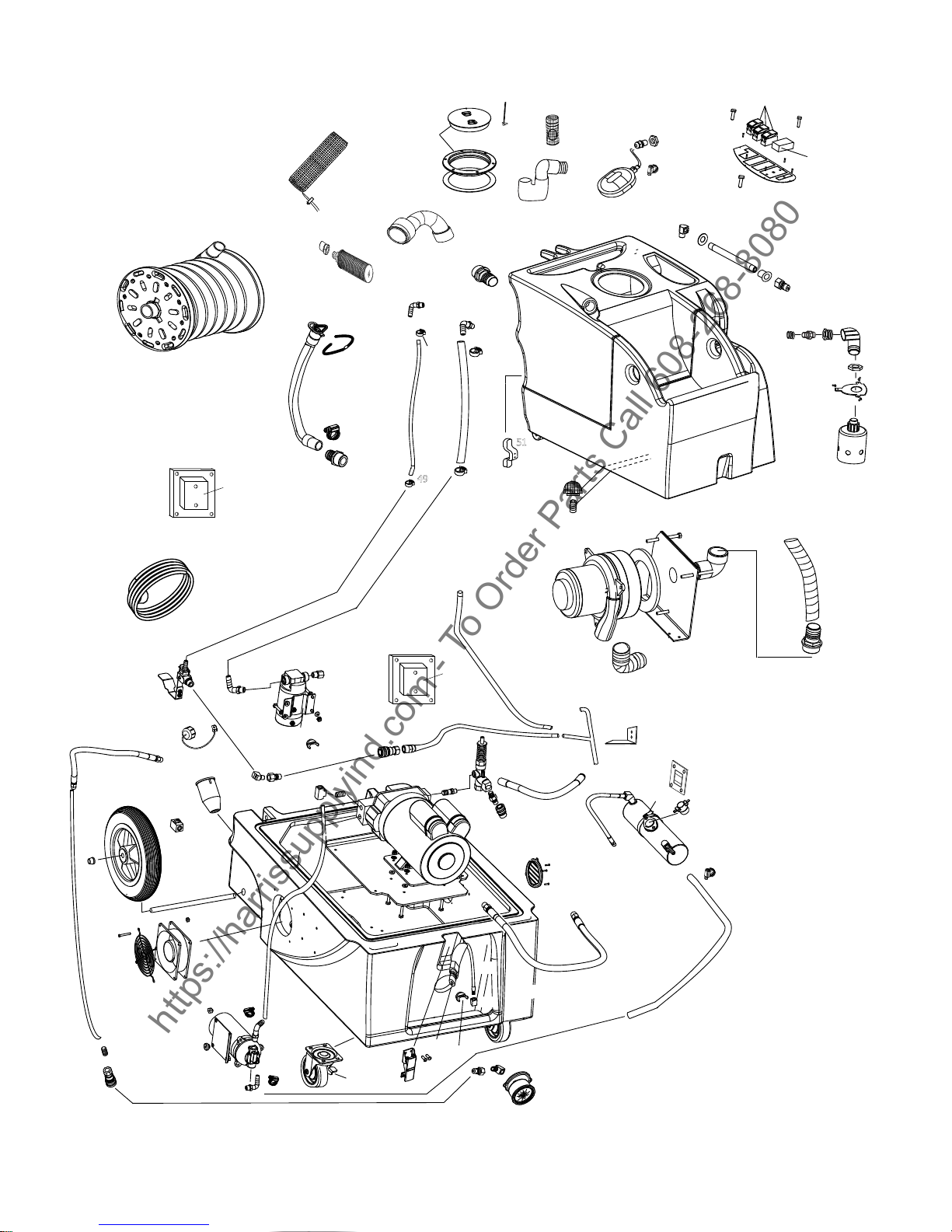
Turbo Force terminator 120V User manual

INFORMATION
&
OPERATING
INSTRUCTIONS
4-2010
IMPROPER USE OF THE MACHINE WILL VOID THE WARRANTY
1. Always use a defoamer when foaming occurs to prevent vacuum motor damage.
2. Before each use, remove the spray tool from the hose, and check to make sure the spray
nozzles are securely tightened to the spray tool. A loose nozzle could fly off during use.
3. Keep machine from rain and snow, extremes in temperatures, and store in a heated
location. Use the machine indoors. Do not use outdoors.
4. Never allow the spray to remain fixed in one spot.
5. Use approved chemicals only. NO SOLVENTS.
6. Never use this machine to strip finish from floors.
7. Never use water above 130º F/54º C in the solution tank.
8. Always use your pre-filter bag and keep both it and all other filters clean.
CAUTION: DO NOT OPERATE MACHINE UNTIL YOU HAVE READ
ALL SECTIONS OF THIS INSTRUCTION MANUAL
56041962
TERMINATOR
120V
https://harrissupplyind.com-ToOrderPartsCall608-268-8080

IMPORTANT SAFETY INSTRUCTIONS
This machine is only suitable for commercial use, for example in hotels, schools, hospitals, factories,
shops and offices other than normal residential housekeeping purposes.
When using any electrical appliance, basic precautions should always be followed, including the
following:
NOTE: Read all instructions before using this machine.
WARNING!
To reduce the risk of fire, electric shock, or injury:
•Do not leave the machine unattended when it is plugged in. Unplug the unit from the outlet
when not in use and before servicing.
•To avoid electric shock, do not expose to rain or snow. Store, and use, indoors.
•Do not allow to be used as a toy. Close attention is necessary when used near children.
•Use only as described in this manual. Use only the manufacturer’s recommended attachments.
•Never add water over 130º F/54º C to the solution tank.
•Do not use with damaged cord or plug. If the machine is not working as it should, has been
dropped, damaged, left outdoors or dropped into water, return it to a service center.
•Protect the cord. Do not: use the cord as a handle, close a door on the cord, or pull the cord
around sharp edges or corners. Do not run the machine over the cord. Keep the cord away from
heated surfaces. To unplug, grasp the plug, not the cord.
•Do not handle the plug, the cord or the machine with wet hands.
•Extension cords must be 12/3 and no longer than 50 feet. Replace the cord or unplug
immediately if the ground prong becomes damaged.
•Do not put any object into openings. Do not use with any opening blocked; keep free of dust,
lint, hair, and anything that may reduce air flow.
•Keep loose clothing, hair, fingers, and all parts of body away from openings and moving parts.
•Do not pick up anything that is burning or smoking, such as cigarettes, matches, or hot ashes, or
any health endangering dusts. Do not use to pick up flammable or combustible liquids such as
gasoline or use in areas where they may be present.
•Turn off all controls before unplugging.
•Use extra care when cleaning on stairs.
•Connect to a properly grounded outlet only.
•Liquid ejected at the spray nozzle could be dangerous as a result of its temperature, pressure, or
chemical content.
SAVE THESE INSTRUCTIONS
https://harrissupplyind.com-ToOrderPartsCall608-268-8080

INSPECTION:
Carefully unpack and inspect your TERMINATOR for shipping damage. Each machine is tested and inspected
before shipping. Any shipping damage incurred is the responsibility of the carrier. You should notify the carrier
immediately if you notice damage to the box or to the machine or parts.
CLEANING SOLUTIONS:
Select a proper pre-spray for the surface to be cleaned, and apply the pre-spray. Use a neutral pH rinse or
detergent (6 to 10 pH) in the King Cobra to prevent premature wear of the pumps, seals, and other components.
Damage caused by the use of improper or harsh chemicals is not covered by warranty. Powders are not
recommended.
MAINTENANCE:
For optimum performance, flush the machine with clear water at the end of each working day. Always use the
pre-filter bag and keep it and both pump inlet filters clean. Once a month, minimum, run a flushing compound
through the machine to break up any mineral or chemical build-up that may have formed. The vacuum motor,
pump motors, and the pumps do not require any scheduled maintenance; however, the motors may require
replacement brushes after 1000 - 1500 hours, and the high pressure pump and unloader valve may require
rebuild kits after 500 -1000 hours (refer to machine part list for numbers). Clean the body with an all purpose
detergent, and protect it with an automobile interior polish. Lubricate the wheels, castors, and quick disconnects
with an all purpose silicone spray.
Record the serial number and model of your new extractor here:
(and be sure to register your purchase to activate your warranty)
Serial Number: __________________ Model: TERMINATOR
Purchase Date:_____________
Write the name and phone number of your distributor:
____________________________________________________________________
____________________________________________________________________
SAVE THESE INSTRUCTIONS
https://harrissupplyind.com-ToOrderPartsCall608-268-8080

Hoses
Vacuum
Hose
Connection
Wheel
Switches
Base
Compartment
Latch
Solution
Tank
1200 PSI
Quick
Disconnect
150 psi
Quick Disconnect
KNOW YOUR MACHINE
Recovery Tank
Dump Hose
Castor
Auto-Dump
Pump
Power
Cord
Recepticle
Power Prime
Pedal
Recovery
Tank
Wand Holder
Wheel
Vacuum Hose
Connection
Recovery
Tank
Auto-fill
Hose
Connector
Wand Holder
Recovery
Tank Lid
https://harrissupplyind.com-ToOrderPartsCall608-268-8080

SWITCH PLATE
CIRCUIT LOCATOR
LIGHTINDICATES
TWO CIRCUITS.
5
HIGH
PRESSURE
PUMP
INDICATOR
DUMPPUMP
ON/OFF
SWITCH
1
PUMP/HEAT
SELECTOR
SWITCH
150 PSI
PUMP
ON/OFF
SWITCH
3
VACUUM
ON/OFF
SWITCH
24HEAT
INDICATOR
1) This light will turn on to indicate the your two power cords are plugged into two circuits. If this light
does not turn on, keep trying outlets with one of the cords until you get the green light to turn on.
Running the machine with out a green light may cause a circuit breaker in the wall to trip.
2) This selector switch determines whether you will use the 1200 psi pump or the heater. You can select
either, but not both. The heater will only work with the 150 psi pump. The center positon is OFF, and
neither the high pressure pump or the heater is turned on.
3) This switch turns the vacuum motor ON and OFF.
4) This switch turns on the low pressure pump for cleaning upholstery or carpet. Turn the selector
switch (#2) to heat if you want to clean with hot water.
5) This switch turns on the automatic pump-out.
SET-UP AND OPERATION
LOW PRESSURE
1. Before each use, inspect the machine, hoses, and cleaning tools for cleanliness and completeness.
Make sure filters and the pre-filter bag are installed and are clean.
Make sure hoses are in good condition and the spray nozzle(s) is tight.
REFER TO THE AUTO-FILL AND AUTO-DUMP INSTRUCTIONS ON THE FOLLOWING PAGES
2. If you choose to use the auto-dump, connect the dump hose to brass hose fitting on the back of the
machine, and place the open end of the hose in a drain. Otherwise, just make sure the brass cap is on
thehose connector. Make sure the recovery tank drain hose is closed, and the lid is tight on the recovery
tank.
3. If you choose to use the auto-fill feature, connect the fill hose to the auto-fill connector (located overthe
https://harrissupplyind.com-ToOrderPartsCall608-268-8080

solution tank fill hole). Turn on the water source, and allow the tank to fill with water. When using the
auto-fill system, the auto-fill float will automatically turn on and turn off as the tank empties and then
fills.
NOTE: If you are not going to use the auto-fill system, just fill the tank with water and cleaning
chemical. Follow chemical directions regarding dilution and mixing. Do not use harsh chemicals; they
may damage seals in pumps and valves, and cause the pump to wear prematurely.
NOTE: Never use water with a temerature exceeding 130
°
F / 54
°
C.
4. Use a pump-up sprayer to pre-spray the area to be cleaned while the tank is filling. Follow chemical
directions.
5. Connect the solution hose (from the reel) to the low PSI quick disconnect on the front of the base of the
machine. Connect the vacuum hose from the center of the reel to the hose barb on the recovery tank.
Connect the vacuum hose on the reel to your cleaning tool.
6. Plug in the two power cords on separate circuits. Do not connect both cords to the same outlet. The green,
‘separate circuit’ locator light (1) on the switch plate should light up. If the locator light does not come on,
check the circuit breaker box in the wall, and/or try different outlets until it does turn on. Although all
systems in the machine may work correctly if you are not on two circuits, a circuit breaker in a wall panel
may trip. If you make sure the green light is turned on, you will prevent tripped ciruit breakers.
7. Turn on the heat by placing the HIGH PRESSURE/HEAT selection switch (2) in the DOWN position.
NOTE: The high pressure pump and the heat can not operate at the same time. NOTE: this switch is off
when it is set to the middle position and neither the heat or the high pressure pump is selected.
8. Turn on the 150 PSI “demand” pump (4). NOTE: the ‘demand’ pump will not run until pressure is
released.
9. Spray for a few seconds to fill the lines with solution. Wait two minutes to allow the heater to reach
temperature.
10. Begin cleaning. It may take several cycles to heat the lines and the cleaning tool.
11.If you are not using the autofill and autodump features, turn off the pump and vacuum when the solution
tank gets low, fill the solution tank, and empty and clean the recovery tank.
12.When finished with the job, turn off the water source. Vacuum the remaining solution from the holding
tank into the recovery tank. Run a few gallons of clean water through the system. Drain the recovery
tank by placing the drain hose over a drain or into a bucket and removing the cap. When the tank is
empty, cap the drain hose and place it back in the velcro holder.
13. Use defoamer to prevent foam, which could result in damage to your vacuum motor.
LOW PRESSURE continued
HIGH PRESSURE WASHER
1. Before each use, inspect the machine, hoses, and cleaning tools for cleanliness and completeness.
Make sure filters and the pre-filter bag are installed and are clean.
Make sure hoses are in good condition and the spray nozzle(s) is tight.
REFER TO THE AUTO-FILL AND AUTO-DUMP INSTRUCTIONS ON THE FOLLOWING PAGES
2. If you choose to use the auto-dump, connect the dump hose to brass hose fitting on the back of the
machine, and place the open end of the hose in a drain. Make sure the recovery tank drain hose is
closed, and the lid is tight on the recovery tank. Otherwise, just make sure the brass cap is on the hose
connector.
3. If you choose to use the auto-fill feature, connect the fill hose to the auto-fill connector (located over the
solution tank fill hole). Turn on the water source, and allow the tank to fill with water. When using the
auto-fill system, the auto-fill float will automatically turn on and turn off as the tank empties and then fills.
NOTE: If you are not going to use the auto-fill system, just fill the tank with water and cleaning
chemical. Follow chemical directions regarding dilution and mixing. Do not use harsh chemicals; they may
https://harrissupplyind.com-ToOrderPartsCall608-268-8080

damage seals in pumps and valves, and cause the pump to wear prematurely.
NOTE: Never use water with a temerature exceeding 130
°
F / 54
°
C.
4. Pre-spray the area to be cleaned, with a pump-up sprayer, while the tank is filling. Follow chemical
directions.
5. Connect the solution hose (from the reel) to the 1200 PSI Quick Disconnect on the front of the tank,
below the switch plate.
6. Plug in the two power cords. Do not connect both cords to the same outlet. The green, ‘separate
circuit locator light (1) on the switch plate should light up. If the locator light does not come on, check
the circuit breaker box in the wall, and/or try different outlets until it does turn on. Although all systems
in the machine may work correctly if you are not on two circuits, a circuit breaker in a wall panel may
trip. If you make sure the green light is turned on, you will prevent tripped ciruit breakers. Turn on the
high pressure pump by placing the HIGH PRESSURE/HEAT selection switch (2) in the UP position, to
select the High Pressure Pump. NOTE: The high pressure pump and the heat can not operate at the
same time. NOTE: this switch is off when it is set to the middle position and neither the high
pressure pump or the heater is selected.
8. Prime the 1200 psi pump using the ‘power prime’ system: turn on both the pump and the vacuum,
cover the hole in the hose barb with your hand, then depress the Power Prime Pedal. This will pull
trapped air through the pump and into the recovery tank, priming the pump. You will notice a ‘tone’
change from the pump (smoother, with less of a rattle), and the water being pulled into the recovery tank
will change to a clear, solid stream. Priming may take 20 - 60 seconds and will require a full solution
tank. When the pump is primed, release the Power Prime Pedal, and turn off the pump and the vacuum.
Depress the Power Prime Pedal once again, for a moment, to release the line pressure. Proceed to the
next step.
9. Use defoamer to prevent foam, which could result in damage to your vacuum motor.
HIGH PRESSURE continued
Rotomolded Body:
Vacuum:
VAC Shutoff:
Pump:
Waterlift:
Heat:
Heater:
Wand:
Weight:
Dimensions:
Lifetime Warranty
7.2” 3-stage
Ball & Float
Positive displacement 1200 psi carpet
140”
Instant to 212 ºF
2000 Watts
Stainless steel, single bend, twin tip
170 lbs.
39”H x 21”W x 36” L
SPECIFICATIONS:
NOTE: Always use the pre-filter bag and keep all filters clean.
Never use the Terminator to strip finish from floors.
CAUTION
: Use care when handling hazardous chemicals.
CAUTION
: Never leave the 1200 psi pump running when you are not actively using it.
DANGER:
Do NOT use solvents, or any chemicals that may be flammable, explosive
https://harrissupplyind.com-ToOrderPartsCall608-268-8080

Operation:
• Attach a 3/4” garden hose to the autofill valve, and connect the other end of the hose to your water source.
• Make sure the float that hangs from the autofill valve into the tank is free of obstruction and can move freely.
• Turn the water supply on.
• The autofill float will automatically shut-off the flow of incoming water when the solution tank is nearly full, and it will
allow the valve to open again once the water level has dropped to a predetermined level.
AUTO-FILL
AUTO-FILL
AUTO-DUMP
Drain Hose
AUTO-DUMP
Power
Prime
Hose
Dump
Pump Power Prime
Pedal
DANGER: always unplug the machine from the electrical outlet(s) before
cleaning or maintaining. Certain internal components are electrically live,
even with switches in their OFF position.
DANGER: DO NOT USE SOLVENTS, OR ANY CHEMICALS THAT MAY BE FLAMMABLE,
EXPLOSIVE OR COMBUSTIBLE.
CAUTION: always use a defoamer in the recovery tank to prevent water or
foam from entering the vacuum motor.
Operation:
•
Before each use:
if necessary, unscrew the stainless steel filter at the bottom of the recovery
tank and clean it. Also make sure the float in the recovery tank is clean.
•
Attach a 3/4” garden hose to the dump pump outlet fitting on the back of the base of the machine.
•
Refer to illustration below
•
Run the other end of the hose into a drain.
•
Turn ON the dump pump switch (switch is located on the switch panel on the top of the machine).
•
NOTE: the dump pump is ‘self-priming.’ You should see water start to flow within 30 seconds of
the pump turning on. If the water level in the tank is high enough to activate the float switch. If
water does not begin to flow, check the filter to see if it is plugged with debris.
•
After each job
: run clear water though the dump pump to wash out any chemical residue.
Remove and clean the stainless steel filter in the back of the tank. Reinstall the filter once it is
clean. Clean and empty the recovery tank.
AUTO-FILL HOSE
CONNECTION
https://harrissupplyind.com-ToOrderPartsCall608-268-8080

10-14-2009
TERMINATOR
82
95
89
98
91
37
41
18
16
17
47
20
21
22
23
24
32
30
5
4
29
34
90
93
35
12
11
10
46
83
79
104
102
83
105
111
117 78
79
121
122
100
123
125
126
128
127
132
131
133
135
124
138
139
140
142
143 144
38
65
66
66A
61
32
49
49
80
32
38
102
48
2
38
135A
51
39
28
64
63
75
111A
136
24
78
137
130
70
31
36
92
92
109
112
TO ITEM #20
TO ITEM
#70
}
69
the complete assembly
26 27
15
14
110
110A
12
43
110
110A
12
43
1
33A
25
99
38
83
107
136
38
67
6
7
33
33A
33B
33D
33C
106
107
108
8
8A
99A
https://harrissupplyind.com-ToOrderPartsCall608-268-8080

TERMINATOR
PART LIST 120V
67 1310A Float,Auto-fill,hightemp.
69 1530 “T” hose assembly, complete
75 220 Quick disconnect, female
78 219 Quick Disconnect, male, open
79 220 Quick Disconnet, female, open
80 1530 Hose, power prime inlet, 30”
82 1163 Valve,pressureregulator
83 92A Nipple, S/S, 1/4 mpt
89 455 Bracket,heatermount
90 FP256 Heatrepairkit
91 76A Hose Clamp, 2-3/4”
92 FP420 Hose,PumptoGauge,complete
93 FP371 HeatExchanger,complete
95 928 Louver,3”,includesscrews
98 1530A Hose,fromunloader,33”
99 1162 HoseAssembly,32”,bypass
100 925 Hose,3/8”X45”pumptoheater
102 152 “T”,brass/1/4npt
104 FP373 Pump & motor, complete
105 1062 Recepticle, power cord
106 957 Pump,auto-dump
106A 1324 HoseConnector,kdumppumpout
107 237 Cap,withchain
108 1325 Elbow,auto-dump
109 1057B PowerCord,25ft,yellow
110 4405A Relay,20Amp
110A 2025 Heat sink plate
111 1164 Valve,powerprime
111A 1299 Pedal, power prime
112 1530C Hose, to highpress.outlet,30”
117 1280 Elbow, 90 degree, brass
121 2084A Wheel, 10”
122 27A Axle cap
123 910-20.75 Axle,1/2”X 21-3/4”
124 1158 Plate, pump mounting
125 16 Locknut, 6-32
126 2B1 Screw,6-32X 2”
127 2015 Guard, fan
128 2014 Fan, cooling, 100CFM
130BKCR BLK Base compartment, black
131 108A Elbow, 90 degree, pump outlet
132 2066 Pump, 150 psi
133 1081 Elbow, 90 degree, pump inlet
135 905 Castor,4”
135A 905A Brake,forcastor
136 1413 Clip Holder, for hose
137 FP416 Hoseassy,lowpress.outltet
138 1043A Gasket
139 219 Quick disconnect, male
140 91 Elbow, 90 degree
142 2166 Gauge,1200psipressure
143 908A Latch
144 21C Screw, 8-32X 5/8”
145 946A Hose, 1/2” 500 PSI, 6-3/4”
1 1303 Switch Plate
2 78 Light,green,120V
3 78B Light,red,120V
3A 227 Light,green,230V
4 56220001 Switch, selector, ON/OFF/ON
5 FP345 Switch, ON/OFF,with actuator
6 FP364 Ballfloat&manifoldassembly
7 929B Ballfloat
8 2068 Float,Auto-Dump
8A 1518 Hoseclamp
9 230 Cordretainer,watertight
10 805 Chain,lidretaining
11 1074 Gasket,recoverylid
12 2086A Lid,andring,6”
14 937 Bushing,PCV
15 2069B Filter,Auto-dump
16 1060C Cap, drain hose
17 1130 Strap,velcro
18 1060B Hose, drain
20 91 Elbow,90degree,brass,1/4mpt
21 1141 Washer,S/S
22 1146 Pipe,S/S,1/4mptbothends
23 1143 Spacer
24 45 Quick Disconnect male, 1/4 pt
25 1184 Hose connector
26 1533 Connector,malegardenhose
27 1571 Bushing, 1” x 1/2”
28 1534 Elbow, 1” 90º
29 2170 Locknut,1”
30 1320A Bracket,Auto-fillvalvemounting
31 1518 Hose Clamp
32 907 Hose Barb,1-1/2” hose
33 1137 Adaptor,ABS,1-1/2”
33A 1140 Elbow, 90º, ABS
33B 1494 Bushing,ABS
33C 1428 Strainerbag
33D 1465A Cordlock
34 HKCR-1 HoldingTank,white
35 VKCR-1 Recovery Tank, white
36 FP414 Reel,withhoses,complete
37 1309 Hose, power prime, 3/8” X 21.25”
38 166 Hoseclamp
39 946A Hose, 1/2” 500 PSI, 17”
41 1115 Elbow,90deg,3/8”hoseX1/4mpt
46 1113 Hose Barb, elbow
47 92B Nipple,PVC,1/2npt
48 207A Filter,Pumpinlet
49 1401 Clamp,quickdisconnect,small
51 CWKC-BLK CordWrap,black
61 1131 Elbow,PVC
64 926 Manifold, vacuum
65 FP323 Vacuum motor, w/gasket, complete
66 430 Vacuumhose, 1-1/2”X 7.75”
66A 1136 Vacuum hose, 1-1/2” X 25 , clear
ITEM PART No. DESCRIPTION ITEM PART No. DESCRIPTION
https://harrissupplyind.com-ToOrderPartsCall608-268-8080

https://harrissupplyind.com-ToOrderPartsCall608-268-8080

NOTES:
TERMINATOR
120V
7905 N. 71st Avenue
Glendale, AZ 85303
PH: 623-414-4356
https://harrissupplyind.com-ToOrderPartsCall608-268-8080
Table of contents
Popular Floor Machine manuals by other brands

Numatic
Numatic TT 345 operating instructions

Minuteman
Minuteman Powerboss PB32036CE Operation service parts care

SPE
SPE DFG460 operating manual

Servpro
Servpro 873 Information & operating instructions

Clarke
Clarke S16 Instructions for use

Nilfisk-Advance
Nilfisk-Advance Hydro-Retriever 2052 CR 1300 Instructions for use

Kärcher
Kärcher BR 530 BAT Package operating instructions

Windsor
Windsor Voyager 2 VGR2 operating instructions

Powr-Flite
Powr-Flite PEB Operator's manual & parts list

Windsor
Windsor COMPASS CMPS 10070050 operating instructions

Sandia Plastics
Sandia Plastics Sniper 2-100 Operation and maintenance manual

Ghibli & Wirbel
Ghibli & Wirbel FR 30 TOUCH Faq