Turbo BTE3211ALP User manual

Manual#P80151126A-Date:2011/01/14
Failuretocomplywiththeseinstructionscould
resultinafireorexplosionthatcouldcause
seriousbodilyinjury,deathorpropertydamage.
Whetherthisgrill wasassembled byyouor
someoneelse,youmustreadthisentiremanual
beforeusing yourgrilltoensurethe grillis
properlyassembled,installedandmaintained.
Use yourgrill atleast3feetaway fromany
wall orsurface. Useyourgrill atleast 3feet
awayfromcombustibleobjectsthatcanmeltor
catchfiresuchasvinylorwood siding,fences
and overhangsorsourcesof ignition including
pilotlightson waterheatersand liveelectrical
appliances.
THISGASAPPLIANCEISDESIGNEDFOROUT-
DOORUSEONLY.
Neverusethisgasapplianceonabalcony,deck,
orpatioabovethegroundfloorofyourhome.
Never useyourgasgrillinagarage,porch,
shed,breezewayoranyotherenclosedarea.
Never obstructthe flowofventilation air
around yourgasgrill housing.
Never disconnectthe gasregulatororanygas
fitting while yourgrillislit. Alitgrill canignite
leakinggasandcauseafireorexplosionwhich
couldresultinpropertydamage,personalinjury
ordeath.
Ÿ
Ÿ
Ÿ
Ÿ
Ÿ
Ÿ
WARNING
! !
Ÿ
Grill Information Center:
Ÿ
Ÿ
NOTETOASSEMBLER/INSTALLER:
Leavethismanualwiththeconsumer.
NOTETOCONSUMER:
Keepthismanualforfuturereference.
RECORDYOURSERIAL#
__________________
(seesilverCSAlabelonmainbodyofgrill)
IMPORTANT:
Ÿ
Operator'sManual
FREEHELP
FROMTHEGRILLEXPERTS
Grand Hall isthe expertonthisproduct
andtrained tohelpyouwith:
visitwww.grandhall.comorcall:
1-877-934-7455
Monday-Friday8:00am-4:30pmCST
AssemblyQuestions
GrillOperation
ReplacementofDamagedorMissingparts
Ÿ
Ÿ
Ÿ
LiquidPropaneGas(LPG)Grill
ModelsBTE3211ALP,BTE3811ALP
NaturalGas(NG)Grill
ModelsBTE3211ANG,BTE3811ANG
BTE3211ALP/NG BTE3811ALP/NG
ByBarbequesGalore. R

2
Donotstoreorusegasolineorother
flammableliquidsorvaporsinthe
vicinityofthisoranyotherappli-
ances.
AnLPcylindernotconnectedfor
useshallnotbestoredinthevicinity
ofthisoranyotherappliance.
1.
2.
•LPGmodelsmustbeusedwithLiquidPropane
Gasandtheregulatorassemblysupplied.Natural
GasmodelsmustbeusedwithNaturalGasonly.
Anyattempttoconvertthe grillfromonefueltype
toanotherisextremelyhazardousandwillvoidthe
warranty.
Keepgas regulatorhoseawayfromhotgrill
surfaces anddripping grease.Avoidunnecessary
twisting ofhose.Visuallyinspecthosepriorto
each use forcuts,cracks,excessive wearorother
damage.If thehose appearsdamageddonotuse
thegas grill.Call1-877-934-7455 foracertified
replacementhose.
CaliforniaProposition 65
Combustionbyproductsproduced when using this
productcontainchemicalsknowntotheStateof
Californiatocausecancer,birthdefects,orother
reproductiveharm.
Brass componentson the grill,such ashose fittings,
propanecylindervalves(soldseparately)and burner
valvestems,containleadwhichisknowntothe State
ofCaliforniatocausecancer,birthdefects,orother
reproductiveharm.
Neveruse charcoal orlighterfluidinthisgas grill.
Failuretocomplywiththese instructionscouldresult
inagrease fireorexplosionthatcouldcauseserious
bodilyinjury,deathorpropertydamage.
TheGreaseTraymustbe visuallyinspectedbefore
each grilluse.RemoveanygreaseandwashGrease
Traywithamildsoap andwarmwatersolution.
Failuretocomplywiththeseinstructions could
resultinagreasefireorexplosionthatcouldcause
seriousbodilyinjury,deathorpropertydamage.
•
•
•
•
!
Thisappliance,when installed,mustbe electri-
callygrounded inaccordancewithlocalcodes
or,inthe absenceoflocalcodes,withthe
National Electrical Code,ANSI/NFPA 70, orthe
Canadian Electrical Code,CSA C22.1.
Keep anyelectricalsupplycordand the fuel
supplyhoseawayfromanyheated surfaces.
•
•
WARNING !
WARNING
! !
WARNING
! !
TableofContents
Primary SafetyWarnings............................1-3
Pre-AssemblyInstructions...............................3
PartDiagramsand Lists............................4-12
Grill AssemblyInstructions.......................13-16
Use&CareInstructions:
•GasSafetyand LeakTests................17-19
• NaturalGasConnection...............................20
•Lighting Instructions......................................21
•Troubleshooting..............................................22
RotisserieInstructions...........................23-25
CleaningandMaintenance.......................26-27
CookingGuide..........................................A1-A4
FrequentlyAsked Questions..................A5-A6
RepairProtectionAgreements......Back Cover
DANGER
!!
1.
2.
3.
4.
Ifyousmell gas:
Shutoff gas totheappliance.
Extinguishanyopenflame.
Openlid.
Ifodorcontinues,keepawayfrom
theappliance andimmediatelycall
yourgas supplieroryourfire
department.
CSA labellocated
on the RearBowl
Panelofthe grill.
Never coverorwraptheCooking Grids,bottom
oftheGrill Bowl,orGrease Traywithaluminum
foil oranyothermaterialthatwill absorbgrease.
! !
WARNING
•
•

Pre-AssemblyInstructionsForYourSafety
WARNING
CAUTION
! !
Failuretocomplywiththeseinstructionsmay result
inahazardoussituationwhich,ifnotavoided,may
resultininjury.
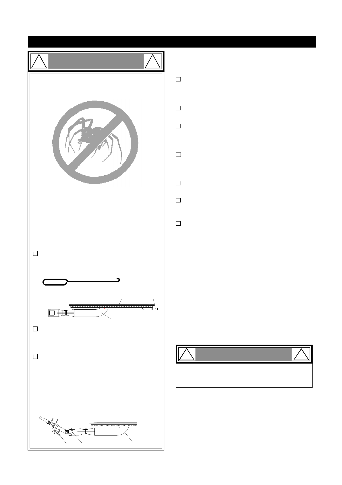
Forsafeoperation ensuretheGas ValveAssem-
blyOrificeisinsidetheBurnerTubebeforeusing
yourgrill.(See figure)IftheOrificeisnotinside
theBurnerTube,lighting theBurnermaycause
explosion and/orfireresulting inseriousbodily
injuryand/orpropertydamage.
METHOD 1:Bend astiff wireorwirecoathanger
intoasmall hook as shownand run thehook
through theBurnerTubeand insidetheBurner
severaltimes toremovedebris.
METHOD 2:Use abottlebrushwithaflexible
handleand run thebrushthrough theBurner
Tube and insidetheBurnerseveraltimesto
removeanydebris.
METHOD 3:Use anairhose toforceairthrough
each BurnerTube.Theforcedairshouldpass
debrisorobstructionsthrough theBurnerand out
thePorts.
TOCLEANBURNERTUBE,
INSERTHOOK
HERE
BurnerTube
9
3
BurnerPort Foot
1.
2.
3.
4. Refertothefigurebelowandperformone ofthese
3cleaningmethods:
CarefullylifteachBurnerupandaway fromtheGas
ValveOrifice.
Checkandclean Burner/VenturiTubesforinsects
andinsectnests.Aclogged tube canlead toafire
beneaththe grill.
Spidersand small insectscanspinwebsand nest
inthegrill BurnerTubes during transitand ware-
housing which canleadtoagas flowobstruction
resulting inafireinand around theBurnerTubes.
Thistypeof"FLASHBACK FIRE"cancause serious
grill damageand createanunsafeoperating con-
dition fortheuser.
Toreduce thechance ofFLASHBACK FIRE
you mustcleantheBurner Tubes as follows
before initialuse. Alsodo thisatleastoncea
monthinsummerand fall orwheneverspidersare
activeinyourarea,and ifyourgrill has notbeen
usedforanextendedperiod oftime.
Remove thescrewsfromtherear ofeachMainBurner
usingaPhillipsHeadScrewdriveroraWrench.
WARNING: Greasecangetveryhot. Alwayshandlethe Grease
Tray withaflameretardantBBQmitt.Beforeremovingthe
Tray,alwaysbe surethatthegrill hasproperlycooled.Be
awarethatthe Traydoescontaingreaseandbeextremely
carefulwhenremoving theTraytopreventspillage.Failure
tofollowthese instructionscouldcause seriousbodilyinjury
orpropertydamage.
Grill Installation Codes
The installationmustconformwithlocalcodesor,inthe
absence oflocalcodes,witheithertheNationalFuelGas
Code,ANSIZ223.1/NFPA54,NaturalGasandPropane.
InstallationCode,CSAB149.1,orPropaneStorageand
HandlingCode,B149.2.
•
•
•
PRE-ASSEMBLY
Readandperformthefollowingpre-assemblyinstruc-
tions:
ToolsRequiredforAssembly:
protectiveworkgloves
protectiveeyewear
You will needassistancefrom2peopletohandlethe
grillheadand otherlarge,heavyparts.
Openlidofshippingcarton.Removetopsheetof
cardboardandpacking materials.Lay cardboardsheet
onflooranduseasaworksurfacetoprotectfloorand
grillpartsfromscratches.
Youmayslicethecartonfrontcornerswithautilityknife
tolayopenthecarton frontpanel.Thisallowsyou to
raise theLidand remove thecomponentspackedin-
side,makingiteasiertolift.
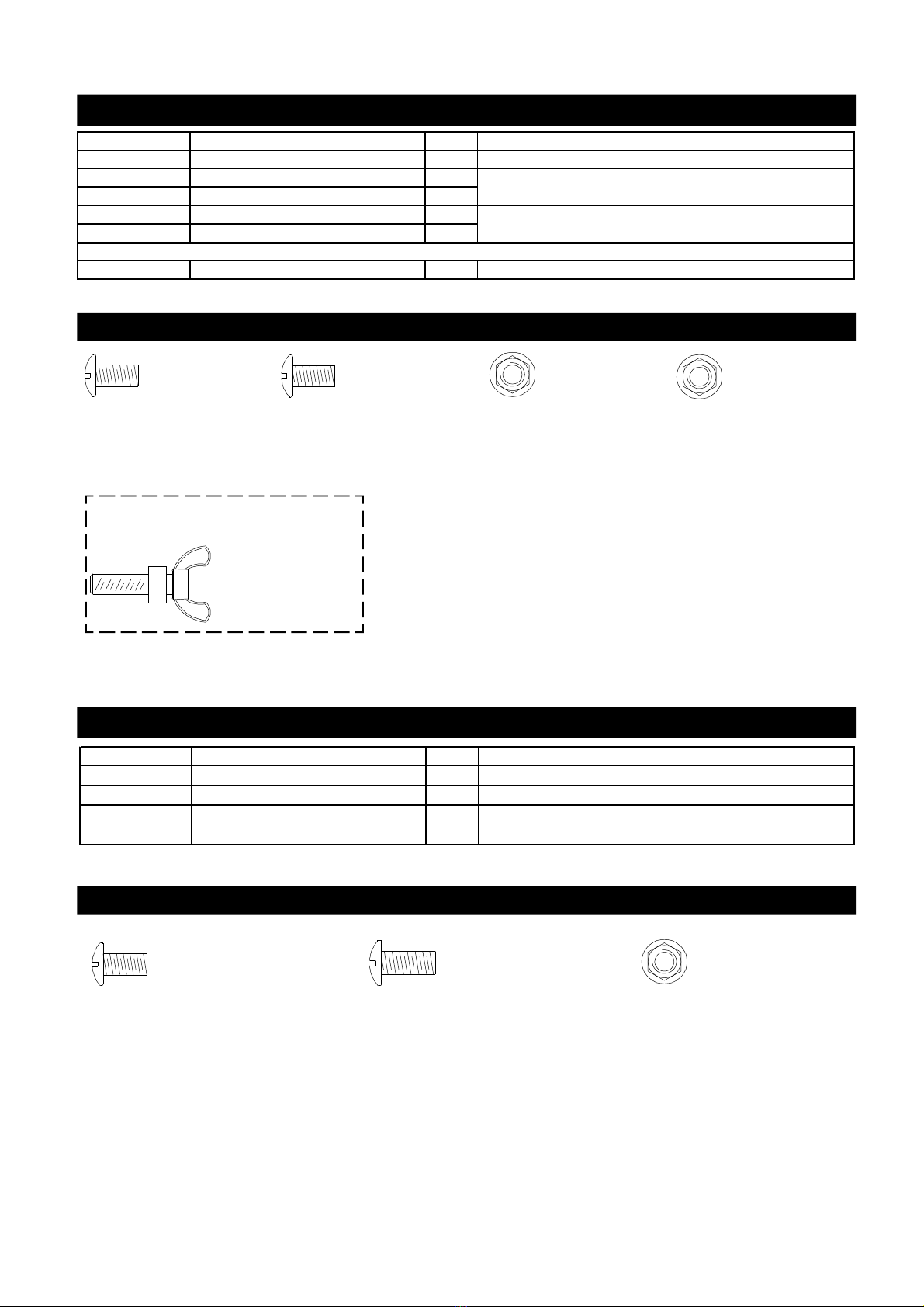
UsetheHardwareandPartDiagramstoensureall items
areincluded andfreeofdamage.
Donotthrowawaythebagsofhardwarethatarein-
cluded withboxedparts.These arerequiredforassem-
bly.
Donotassembleoroperatethe grillifitappearsdam-
aged.If therearedamagedormissingpartswhenyou
unpacktheshippingboxoryou havequestions during
theassemblyprocess call 1-877-934-7455 M-F8AM-
4:30PMCSTforassistance.
CAUTION !
Whenusing electricalappliances,basicsafety
precautionsshould always beused.
!
PhillipsHeadScrewdriver
Orifice BurnerTube
GasValveAssembly

4
Hardware PartsList for Models BTE3211ALP
Hardware Diagramfor Models BTE3211ALP
PART# PARTDESCRIPTION QTY PURPOSEOFPART
P06030016A HardwarePack 1 ForuseinassemblyBTE3211ALP
S112G0306A PhillipsHead Screw3/16"x3/8" 2
S313G0306A FlangeNut 3/16" 2
S112G0306B PhillipsHead Screw3/16"x3/8" 4
S313G0306B FlangeNut 3/16" 4
S233G04084 WingBolt1/4"x1/2" 1 Install TankHolderAssembly
Install the TankHolder Brackets
Install the LPRegulatorBracket
Alreadyinstalledon theTankHolder
Hardware Diagramfor Models BTE3211ANG
Hardware Pack for Model BTE3211ANG
*OneBattery/AA includedin theHardwarePack
PART# PARTDESCRIPTION QTY PURPOSEOFPART
P06030017A HardwarePack 1 For useinassemblyforModelsBTE3211ANG
S112G03041 PhillipsHead Screw3/16"x1/4" 2 Installthe NGRegulator
S112G03081 PhillipsHead Screw3/16"x1/2" 3
S313G03051 Flange Nut3/16" 3 InstallNGRegulatorBracket
PhillipsHeadScrew
3/16"x1/2"
Qty.3
Part#S112G03081
PhillipsHeadScrew
3/16"x1/4"
Qty.2
Part#S112G03041
FlangeNut3/16"
Qty.3
Part#S313G03051
*OneBattery/AA includedin theHardwarePack
Wing Bolt1/4"x1/2"
Qty.1
Part#S233G04084
ForInstalling theTankHolderAssembly
(Alreadyinstalledin TankHolderAssembly)
PhillipsHeadScrew
3/16"x3/8"
Qty.2
Part#S112G0306A
FlangeNut3/16"
Qty.2
Part#S313G0306A
PhillipsHeadScrew
3/16"x3/8"
Qty.4
Part#S112G0306B
FlangeNut3/16"
Qty.4
Part#S313G0306B

5
*OneBattery/AA includedin theHardwarePack
Hardware PartsList for Model BTE3811ANG
Hardware Diagramfor Model BTE3811ANG
PART# PARTDESCRIPTION QTY PURPOSEOFPART
P06030019A HardwarePack 1 For useinassemblyforBTE3811ANG
S112G03041 PhillipsHead Screw3/16"x1/4" 2 Install the NGRegulator
S112G03081 PhillipsHead Screw3/16"x1/2" 3
S313G03051 Flange Nut3/16" 3 Install NGRegulatorBracket
Hardware Diagramfor Models BTE3811ALP
Hardware PartsList for Models BTE3811ALP
PART# PARTDESCRIPTION QTY PURPOSEOFPART
P06030018A HardwarePack 1 Foruseinassemblyfor BTE3811ALP
S112G0306A PhillipsHead Screw3/16"x3/8" 2
S313G0306A Flange Nut3/16" 2
S112G0306B PhillipsHead Screw3/16"x3/8" 4
S313G0306B Flange Nut3/16" 4
S233G04084 Wing Bolt1/4"x1/2" 1 InstallTankHolderAssembly
Alreadyinstalledon theTankHolder
Installthe TankHolder Brackets
Installthe LPRegulator Bracket
PhillipsHeadScrew
3/16"x1/2"
Qty.3
Part#S112G03081
PhillipsHeadScrew
3/16"x1/4"
Qty.2
Part#S112G03041
FlangeNut3/16"
Qty.3
Part#S313G03051
*OneBattery/AA includedin theHardwarePack
Wing Bolt1/4"x1/2"
Qty.1
Part#S233G04084
ForInstalling theTankHolderAssembly
(Alreadyinstalledin TankHolderAssembly)
PhillipsHeadScrew
3/16"x3/8"
Qty.2
Part#S112G0306A
FlangeNut3/16"
Qty.2
Part#S313G0306A
PhillipsHeadScrew
3/16"x3/8"
Qty.4
Part#S112G0306B
FlangeNut3/16"
Qty.4
Part#S313G0306B

PartsDiagramforModelsBTE3211ALP/NG
6
49
48
32B
29
6
45
L1
47
46
44
5
4
3
2
1
40
28
27
30
41
42
L5
26
25
24
23 22
21 20
17
18
15
L239 38
37
36
35
33
16
B6 B5
L3
L4
B2
B1
4334
L6
14
13 12
11
10
9
87
31
B4
B3
19
32A

PartsList forModelBTE3211ALP/NG
7
KEY DESTRIPTION PART# QTY.
1LidAssembly P0015410EA 1
2TemperatureGauge P00601071A 1
3ProtectivePad P05518002I 4
4 LidHandleBracket, Left P03303124A 1
5LidHandleBracket, Right P03303125A 1
6LidHandleHeatInsulating Spacer P06802007A 2
7LidHandle P00218009A 1
8Cooking Rack/Secondary P01515030K 1
9Cooking Grid P016150436 3
10 FlameTamer/CeramicSupport P01720040A 4
11 FlameTamer/Ceramic P01801005A 52
12 FlameTamer/CeramicSupport Bracket P03333006A 4
13 Burner BracketAssembly P02209224A 1
14 Burner/Main P02003003B 4
15 BowlSide Panel,Left P0072099PC 1
16 BowlSide Panel,Right P0072199PC 1
17 BowlSide Panel,Front P0073885DC 1
18 BowlSide Panel,Rear P0075806DC 1
19 GreaseTrayHeatShield P06904052C 1
20 GasCollectorBoxwithElectrode P02609015B 4
21 ElectricWireSet P02616070A 1
22 ElectricWire,5-contact P02627015A 1
GasValve/ManifoldAssembly(LPG) Y0060753 1
GasValve/ManifoldAssembly(NG) Y0060754 1
24 LEDLightWireSet P02615179A 1
25 ControlPanel,Upper P02908481S 1
26 ControlPanel P02908506S 1
27 ControlKnob withLEDLight P03415313L 5
28 ControlKnob P03411533L 4
29 ControlKnob forBackBurner P03411543L 1
30 ElectricIgnitor, 5ports P02502298C 1
31 ElectricIgnitor Protector P03328048Q 1
32A BowlTrimBracket, Left P07901041D 1
32B BowlTrimBracket, Right P07901042D 1
33 GreaseDraining Plate P06902017S 2
34 BowlTrimBracket, Rear P07901040D 1
35 BowlTrimBracket, Front P07901043D 2
36 LightingTube P05507141E 1
37 Extension Fitting forManifold P03902029A 1
38 GasValve/ManifoldExtension P05005482G 1
39 Extension Tube P03720003A 1
40 BowlBracket, Left P01301014A 1
41 BowlBracket, Right P01302014A 1
42 GreaseTrayAssembly Y0270029 1
23

8
PartsList forModelsBTE3211ALP/NG
KEY DESTRIPTION PART# QTY.
43 BowlWind Shield, Rear P06906087C 1
44 RegulatorwithHose(LPG) P03601045A 1
45 TankHolder Assembly(LPG) P05358003T 1
46 Bracket forNGRegulator(NG) P033040544 1
47 NGRegulator(NG) P03614009B 1
48 RegulatorHose(NG) P03705092F 1
49 Hose, 12 ft(NG) P03703001A 1
B1 BackBurner Assembly P02007074A 1
B2 BackBurner Electrode P02614025A 1
B3 BackBurner Thermocouple P05305069B 1
B4 BackBurner ThermocoupleBracket P03328047C 1
B5 BackBurner Orifice P06534009A 1
B6 BackBurner Extension Tube P03717062B 1
L1 GFCIOutlet/Transformer Assembly P05374017B 1
L2 LightWireSet P05352008B 1
L3 Light,12V, 10W P05383002B 2
L4 LightCover, Rear P05383003B 2
L5 LightSwitch P05360002B 1
L6 LightSetHoldingFrame P06906089C 1
HardwarePack P06030016A 1
HardwarePack P06030017A 1
Operator'sManual P80151126A 1

PartsDiagramforModelsBTE3811ALP/NG
9
5
53 54
55
52
51
50
36
33
34
37
29
16
L1
17
15
14
13
40
39
35
L5
27
28
23
30
38
32
31
26 25
24
20
12
11
B1
21
18
B2
10
47
48
44 45
19
46
L2
43
42B
22
L6
41
49
B3
B4
B5
L4L3
B6
9
7
8
4
62
3
1
42A

KEY DESTRIPTION PART# QTY.
1LidAssembly P0014518EA 1
2TemperatureGauge P00601071A 1
3ProtectivePad P05518002I 4
4 LidHandleBracket, Left P03303124A 1
5LidHandleBracket, Right P03303125A 1
6LidHandleHeatInsulating Spacer P06802007A 2
7LidHandle P00218010A 1
8Cooking Rack/Secondary P01515031K 1
9Cooking Grid P016150436 2
10 Cooking Grid P016050036 1
11 FlameTamer/CeramicSupport P01720040A 3
12 Burner Heat Shield P069060454 1
13 FlameTamer/Ceramic P01801005A 39
14 FlameTamer/CeramicSupport Bracket P03333006A 4
15 Burner BracketAssembly P02205154A 1
16 Burner/Main P02003003B 3
17 Burner/Infrared P02005010A 1
18 BowlSide Panel,Left P0072099PC 1
19 BowlSide Panel,Right P0072199PC 1
20 BowlSide Panel,Front P0075813DC 1
21 BowlSide Panel,Rear P0073896DC 1
22 GreaseTrayHeatShield P069040534 1
23 GascollectorboxwithElectrode P02609015B 3
24 Infrared BurnerElectrode P02618060A 1
25 Infrared BurnerThermocouple P05305051A 1
26 Infrared BurnerThermocoupleBracket P03328047C 1
27 ElectricWireSet P02616071A 1
28 ElectricWire,5-contact P02627016A 1
Manifoldand GasValve- LPG Y0060756 1
Manifoldand GasValve- NG Y0060756 1
30 LEDLightWire P02615180A 1
31 ControlPanel,Upper P02914336S 1
32 ControlPanel P02914346S 1
33 ControlKnob withLEDLight P03415313L 5
34 ControlKnob/MainBurner P03411533L 3
35 ControlKnob P03411543L 2
36 ElectricIgnitor, 5ports P02502298C 1
37 ElectricIgnitor Protector P03328048Q 1
38 BowlBracket, Left P01301014A 1
39 BowlBracket, Right P01302014A 1
40 GreaseTrayAssembly Y0270028 1
41 BowlTrimBracket, Rear P07901045A 1
42A BowlTrimBracket, Left P07901041D 1
42B BowlTrimBracket, Right P07901042D 1
43 GreaseDraining Plate P06902017S 2
29
PartsList forModelBTE3811ALP/NG
10

KEY DESTRIPTION PART# QTY.
44 BowlTrimBracket,Front P07901043A 2
45 Lighting Tube P05507141E 1
46 Extension Fittingfor Manifold P03902029A 1
47 GasValve/ManifoldExtension P05005482G 1
48 Extension Tube P03720003A 1
49 BowlWindShield,Rear P06906088C 1
50 RegulatorwithHose(LPG) P03601045A 1
51 TankHolder Assembly(LPG) P05358003T 1
52 Bracketfor NGRegulator(NG) P033040544 1
53 NGRegulator (NG) P03614009B 1
54 RegulatorHose(NG) P03705092F 1
55 Hose,12ft (NG) P03703001A 1
B1 BackBurner Assembly P02007075A 1
B2 BackBurner Electrode P02614025A 1
B3 BackBurner Thermocouple P05305070A 1
B4 BackBurner ThermocoupleBracket P03328047C 1
B5 BackBurner Orifice P06534009A 1
B6 BackBurner Extension Tube P03717063B 1
L1 GFCIOutlet/TransformerAssembly P05374017B 1
L2 LightWireSet P05352016B 1
L3 LightCover P05383003B 2
L4 Light,12V,11W P05383002B 2
L5 LightSwitch P05360002B 1
L6 LightSet Holding Frame P06906090C 1
HardwarePack (LPG) P06030016A 1
HardwarePack (NG) P06030017A 1
Operator'sManual P80151126A 1
PartsList forModelsBTE3811ALP/NG
Important: UseonlyGrand Hall replacementparts.TheuseofanypartthatisnotaGrand Hall replacementpartcanbe
dangerousand will alsovoid yourproductwarranty.Keep thisOperator'sManualforconvenientreferralandforpart
replacement.
Fortherepairorreplacementpartsyouneed:
Call 1-877-934-7455 M-F8AM-4:30PMCST
Toobtain thecorrectreplacementpartsforyourgasgrill,pleaserefertothepartnumbersin thispartslist. The
following informationisrequiredtoensureyoureceivethecorrectparts:
1.Modeland SerialNumber(see CSA labelongrill)
2.PartNumber
3.PartDescription
4.Quantityofpartsneeded
11

KEY
1.
2.
3.
4.
5.
6.
7.
8.
9.
PART#
DESCRIPTION QTY
1
3
1
1
2
1
1
2
2
2
12
CustomerServiceHelpline:Ifyouhavequestionsaboutassemblyorgrilloperation,oriftherearedamagedor
missingpartswhenyouunpackthisunitfromtheshippingbox,callus8:00am-4:30pmCST,Mondaythrough
Fridayat1-877-934-7455
HardwareforRotisserie
6
7
9
8
5
4
4
2
2
3
2
1
Rot. Collar
Rot. Thumbscrew1/4"x1/2"
Rot. Spit(forBTE32ALP/NG Models)
Rot. Spit(forBTE38ALP/NG Models)
Rot. Holding Fork
Rot. MotorBracket
Rot. Motor/AC
Rot. Screw#10-24x3/4"UNC
Rot. Washer3/16"
Rot. Nut#10-24
P05508177A
S196G04081
P05508203A
P05508057A
P05508023A
P05508174A
P07101031B
S112G10121
S411G03081
S362G10121
RotisserieScrew
#10-24x3/4"UNC
Qty.2
Part #S112G10121
RotisserieNut#10-24
Qty.2
Part #S362G10121
RotisserieWasher
Qty.2
Part #S411G03081
RotisserieThumbscrew
1/4"x1/2"
Qty.3
Part #S196G04081
RotisserieAssemblyPartsDiagramforBTE3211ALP/NG&BTE3811ALP/NG
RotisserieAssemblyPartsListforBTE3211ALP/NG&BTE3811ALP/NG

AssemblyInstructionsforBTE3211ALP/NG&BTE3811ALP/NG
CAUTION :Whileitispossibleforone person toassemblethisgrill,obtainassistancefromanotherpeople
whenhandlingsomeofthelarger,heavierpieces.
1Install Grill Head
Withthehelpofyourassistants,place the Grill Head intothe cutoutofyourgrillisland(See Diagram).
NOTE:The grillhead isdesignedtofitintoanisland ofyourowndesign.Theislandshownin
thediagramisforillustration purposesonly.Thediagramisnotdrawntoscale.Anisland isnot
includedwiththepurchaseofthisgrillhead.Besureyourisland meetstheconstructionguidelines
andclearances as indicatedinpages17and18.
13
Connectthe TransformertoPowerSourceandturnonthe GrillLights(forBTE3211ALP/NG&
BTE3811ALP/NG Models)
2
Anisland isshownforillustrative
purposesin thediagram.
Makeaholeon yourRearIsland PanelfortheTransformerCord.PulltheTransformerCordout
throughthehole,and make surethecorddoesn'ttouchtheground.(TheRearIslandPanelis
notincludedwiththepurchase oftheGrill Head.)
Plug TransformerCordintoaproperlygrounded outlet.
PushtheLightSwitch on theControlPaneltoturnonthelights.
MaketheholeonyourRearIsland
Panelsothecordcanbepulledout
RightIsland forinstalling a
Gas Tank

14
3Install NGRegulatorand 12 FootHose (forBTE3211ANG&BTE3811ANGModels)
Install theNG RegulatorontotheRegulatorBracketusing 2PhillipsHeadScrews3/16"x1/4".
ConnectNG Gas Fitting withHose totheGas Manifold.Install theNG RegulatorBrackettoyour
RearIsland Panelusing 3PhillipsHeadScrews3/16"x1/2"and tightenusing 3FlangeNuts
3/16"as shown.
ConnecttheSwivelNutofthe12 footHose totheNG Gas Regulator.
CAUTION:Buildyourgrill island beforeinstalling theLPGas Tank and Partition Panel(Notincludedinthisunit).
RefertotheheightslistedinFig.4forconstructing yourgrill island.Anisland unitisnotincludedwiththepurchase
ofyourGrill Head.
Swivel Nut
Vertical Fitting
GasManifold
12'Natural
GasHose
PhillipsHeadScrew
3/16"x1/2"
Qty.3
Part#S112G03081
PhillipsHeadScrew
3/16"x1/4"
Qty.2
Part#S112G03041
FlangeNut3/16"
Qty.3
Part#S313G03051
AB
PhillipsHeadScrew
3/16"x3/8"
Qty.2
Part#S112G0306A
FlangeNut3/16"
Qty.2
Part#S313G0306A
PhillipsHeadScrew
3/16"x3/8"
Qty.4
Part#S112G0306B
FlangeNut3/16"
Qty.4
Part#S313G0306B
Wing Bolt1/4"x1/2"
Qty.1
Part#S233G04084
ForInstalling theTankHolderAssembly
(Alreadyinstalledin TankHolderAssembly)
Install TankHolderBrackets,Tank HolderAssembly,andLPGasTank
(forBTE3211ALP &BTE3811ALPModels)
4InstalltheBracketwithRegulatorontothe IslandSidePanelusing2black Phillips HeadScrews
3/16"x3/8"and 2blackFlange Nuts3/16".(Seediagram)
InstalltheStainless SteelTube (notincludedinthisunit)ontothemanifold.Next, insert the other
endoftheStainlessSteelTubethroughtheholeon theIsland'sSide Panel.Install theStainless
SteelTubeontothemalefittingontheRegulator.
InstalltheTankHolderBracketsontotheTankTrayusing4Phillips HeadScrews3/16"x3/8"and
tighten securelyusing4FlangeNuts3/16"as shown.Besurethatthe flatsurfacesoftheTank
HolderbracketsarepositionedtowardstheTankHoldercenterasshownbelow.
InserttheARingoftheTank HolderintotheTankHolderBrackets.Insertthe BoltontheBRing
intotheLeftTank HolderBracketas shown.
Placethe LPGasTank intothe Tank Holdersothatthe tank valve facestherightcorner.Tighten
theWing Bolt tosecuretheTank inplace.
InstallLPRegulatorontotheGasTank.
A
B
Fig. 3
Island Bottom
Panel
ARing ofthe
TankHolder
BRing ofthe
TankHolder
NotProvided
NotProvided

15
Install IgnitorBattery
RemoveIgnitorCapfromControlPanel.
PlacesuppliedAA batteryintotheIgnitorSlotwithpositivepolefacing you.
Position theCapand Spring overtheAA batteryand tightenontoControlPanel.
6
InstallthePartition Panel(notincludedinthisunit) ontotherightisland.
Makesurethereis22-24"ofclearancebetween thePartitionPanelandthe
Tank HolderAssembly.
5InstallPartitionPanel(forBTE3211ALP &BTE3811ALPModels)
IgnitorCap
IgnitorSlot
AA Battery
Spring
Fig. 4
TankHolder
Assembly
1"
5" 17-19"
PartitionPanel
(abovetheGasTank)
5"
VentOpeningsmust
beatleast1/8"wide.
22-24"
21"
+-

16
MainBurnerElectrode Check
Withtheassistanceofanotherperson,
performthisElectrode Check beforepro-
ceeding.
7
Thistestwillensurethatthe SparkElectrode Tips
areproperlypositionedso yourgrilllightseasily.
(forBTE3211ALP/NG)
FinalGrill AssemblyStep
When you havefinished assemblingyourgrill,
besurethatallscrewsaretightenedforsafe
operationofyourgrill.
Beforeeachuseofthegrill,makesurethe
GreaseTrayisfullyseatedundertheGrillBowl.
CAUTION:TheGreaseTrayshouldbe inspected
beforeeach grilluse tobesurethereisno ex-
cessivegrease buildup.CleantheGreaseTray
frequentlytoeliminategreasebuild-upandto
preventgrease fires.
CookingRack/Secondary
Cooking Grids
FlameTamer
FlameTamerRack
CookingRack/Secondary
Cooking Grids
FlameTamer
SparkElectrodeTip
SparkReceiver
SparkGap3/16"
GasCollector
Box
Install Cooking Components
8PlacetheFlameTamerRack insidetheGrill
Bowl.Position itontothelowerledgeofthe
Bowlabovetheburners.Next, placetheFlame
Tamerson theFlameTamerRack.(See the
diagramson right)
PlacetheCooking Gridson theledgeabove
theFlameTamers.
PlacetheSecondaryCooking Rack intothe
slotson Grill BowlSidePanels.
AA Batterymaybeinstalledbackwards.
Electricwires maybe loose.Removethe AA
Batteryandinspectthe IgnitorJunctionBox
found behind the ControlPaneland recon-
nectanyloose wires.
-
-
Besureall ControlKnobsaresetto"OFF"and
opentheGrill Lid.
Haveyourassistantstand behind totheright
ofthegrill and look towardthefrontofthegrill
bowl. Never putyourfaceinsidetheGrill
Head.
Press theIgnitorCap.You shouldheara
"clicking"sound.Yourassistantshouldsee a
bluesparkwithineach Gas CollectorBox.If
asparkispresenttheElectrodeTipsare
properlypositioned.
Ifno sparkisseen,theSparkGapneedsto
beadjustedas follows:
•
•
IfthegapbetweentheSparkElectrodeTip
and Receiverismorethan3/16"wideuse
needlenose plierstogentlysqueeze the
SparkReceivertonarrowgap.
Recheck theElectrodeagain,ifno "clicking"
sound isheard:
(forBTE3811ALP/NG)
FlameTamerRack

17
USE AND CAREINSTRUCTIONS
CORRECTLP GASTANK USE
The LPGastankmustbe constructed andmarkedin
accordancewiththe Specifications forLP-GasCylinders
oftheU.S.DepartmentofTransportation(D.O.T.)orthe
NationalStandardofCanada,CAN/CSA-B339,Cylinders,
SpheresandTubesforTransportationofDangerous
Goodsand Commission;as applicable.
The LPGastankmusthave ashutoffvalve,terminating
inanLPGassupplytankvalveoutlet,thatiscompatible
withaType 1tankconnectiondevice.TheLPGastank
mustalsohave asafetyreliefdevicethathasadirect
connectionwiththe vaporspace ofthetank.
The tanksupplysystemmustbe arranged forvapor
withdrawal.
The LPGastankmusthave acollartoprotectthe tank
valve.
Neverconnectan unregulated LPgastanktoyourgas
grill. Thegasregulatorassemblysupplied withyourgas
grillisadjustedtohavean outletpressureof11"water
column(W.C.)forconnectiontoan LPgastank.Only
usethe regulatorandhoseassemblysupplied withyour
gasgrill.Replacementhoseand regulatorassembly
mustbe identicaltothoselisted inthe partslistofthis
Operator'sManualasspecifiedbyGrandHall.
Have yourLPGasdealercheckthereleasevalve after
everyfillingtoensureitremains freeofdefects.
Always keepLPGastankinuprightposition.
DonotsubjecttheLPGastanktoexcessive heat.
Neverstorean LPGastankindoors.Ifyoustoreyour
gasgrillinthegarage always disconnectthe LPGas
tankfirstandstoreit safelyoutside.
LPGastanksmustbestored outdoorsinawell-
ventilated areaandoutofthe reachofchildren.
Disconnected LPGastanks mustnotbestoredina
building,garageoranyotherenclosed area.
The regulatorandhose assemblycanbe seenby
openingthe IslandCabinet.Theymustbeinspected
beforeeachuseofthegrill. Ifthe hoseisdamagedin
anyway,itmustbe replacedpriortousingthe grillagain.
Anyattempttoconvertthe grillfromone fueltype to
anotherisextremelyhazardous andwillvoidthe war-
ranty.
Neverlightyourgas grillwiththelidclosed orbefore
checkingtoensuretheburnertubesarefullyseatedover
thegasvalve orifices.
Neverallowchildrentooperateyourgrill.Donotallow
children orpetstoplay nearyourgrill.Always supervise
children andpetsiftheyareinthe vicinityoftheunit.
Never use charcoalorlighterfluidinthisgrill.
Useofalcohol,prescriptionornon-prescriptiondrugs
canimpairyourabilitytoproperlyassembleand
safelyoperateyourgrill.
Keep fireextinguisherreadilyaccessible.Intheevent
ofaoil/greasefire,donotattempttoextinguishwith
water.Usetype Bextinguisherorsmotherwithdirt,
sandorbakingsoda.
Intheeventofrain,turnofftheburnersandgas
supply.Wait forthegrilltocool,andthen placea
coveronit.
Useyourgrillonalevel, stablesurface inanarea
clearofcombustiblematerials.
LPGasgrillmodelsaredesignedforusewithastandard
20lb.LiquidPropane Gas(LPGas)tank(soldsepa-
rately). Never connectyourgasgrilltoan LPGastank
thatexceedsthiscapacity.Atankofapproximately12
inchesindiameterby18-1/2incheshighisthemaximum
sizeLPGastanktouse. Youmustusean "OPD"gas
tankwhichoffersalistedOverfill PreventionDevice.
Thissafetyfeaturepreventstankfrombeingoverfilled
whichcancauseamalfunctionofthe LPGastank. Donotleave grillunattendedwhen inuse.
Donotmovethe appliance when inuse.
Allowthe grilltocoolbeforemovingorstoring.
Donotuseyourgrillasaheater.
Neveruseyourgasgrillonabalcony,deck,patio
abovethe groundfloorofyourhome.
Thisgrillisnotintendedtobe installedinoron
recreationalvehiclesand/orboats.
The grillisnotintended forcommercialuse.
!
DonotstoreaspareLP-Gastank underornear
thisappliance.
Neverfillthetankbeyond80percentfull; and
Ifthe information in"(a)"and"(b)"isnotfollowed
exactly,afirecausingdeathorseriousinjurymay
occur.
A.
B.
C.
WARNING !
!WARNING !
Refertothethistablewhendesigningtheislandunit
forthe BTE3211ALP/NG&BTE3811ALP/NGSide*and
Rear*showtheminimumamountofdistance the unit
mustbe fromcombustibles(ex.Vinylorwoodsiding,
fencesandoverhangs)orsourcesofignition(ex.Pilot
lightsonwaterheatersandliveelectricalappliances).
Height*showsthe minimumheighttheislandunit
mustbe startingfromthe groundup.
Side*
Depth
Height
Width
Non-combustible
Construction
Rear*
7"minimum
clearancefrom
cutout(forlid)
Height*
Model Height Width Depth Side* Rear*
Height*
BTE3211
ALP/NG 9-1/2" 30-1/2"21-1/2" 36" 36" 29"
BTE3811
ALP/NG 9-1/2" 38-1/2"21-1/2" 36" 36" 29"

18
USE AND CAREINSTRUCTIONS
BrushsoapysolutionontoLPGastankinthear-
easindicatedbythearrows.Seediagram.
Ifgrowingbubbles appeardo notuseormovethe
LPGastank.Callan LPGasSupplieroryourFire
Department.
NOTEaboutLPGas Tank Exchange Programs
Manyretailersthatsell grillsofferyou theoption of
replacing your emptyLPGas tank through anexchange
service.Useonlythosereputableexchangecompa-
nies thatinspect, precision fill,testandcertifytheir
tanks.Exchangeyourtank onlyforanOPD safetyfea-
ture-equipped tankas described inthe LPGastank
sectionofthisguide.
Ÿ
How toLeak TestyourLPGas Tank
Use acleanpaintbrushand a50/50 mildsoapand
watersolution.
Ÿ
Ÿ
Ÿ
Foryoursafety:
Leaktestnewand exchangedLPGas tanksBEFORE
connecting onetoyourgrill.
Alwayskeepnewand exchangedLPGastanksinan
uprightpositionduringuse,transitorstorage.
All leaktestsmustberepeatedeach timeyourLP
Gastank isexchangedorrefilled.
Whencheckingforgas leaksdonotsmoke.
Donotusean openflametocheckforgas leaks.
Yourgrill mustbe leaktestedoutdoorsinawell-ven-
tilatedarea,awayfromignitionsourcessuchasgas
firedorelectricalappliances.During the leak test, keep
yourgrillaway fromopen flames orsparks.
Donotusehouseholdcleaningagents.Damage to
gas assemblycomponentscanresult.
Ÿ
Ÿ
Ÿ
Ÿ
Ifgrowingbubbles appeardo notuseormovethe
LPGastank.Contactan LPGas Supplieroryour
firedepartment!
WARNING
!!Note:Thebuilt-inapplianceforuse witharemoteself-con-
tained LPGas supplysystemmustuserigidpipe,semi-
rigidtubing oraconnectorcomplying withtheStandardfor
ConnectionsforGas Appliance,ZNSIZ21.24/CSA6.10.
Securea20lbLP Gas Tank toGas Grill
(forBTE3211ALP &BTE3811ALP)
NOTE: Whenusing Propane,EXTREMECAUTION
shouldbeusedtoprovideampleventilation ofvapor
fromtheenclosure.LPGas vaporisheavierthanair
and SERIOUSINJURYfromaDANGEROUS EXPLO-
SION couldoccurifLPGas isallowedtoaccumulate
inanenclosureand thenignited.BoththeBarbecue
enclosureand LPcylinderenclosurerequireventing
thatmustbeprovidedatthefloorleveloftheenclo-
suretoallowanyleaking LPGas vaportoescape
(see Fig.1).
NOTE: Wheninstalling abarbecueequippedforliquid
propaneinanisland,thepropanetank mustbein
aseparateenclosurethatiscompletelyisolatedfrom
thebarbecue.Itmustbecross-ventilatedinaccor-
dancewiththecurrentstandards.Thepropanetank
MUSTNEVER beinstalleddirectlyunderthebarbe-
cue.
NOTE:Thetotaloftheupperventilation openings
mustbeaminimumof20 sq.inches.Thetotalof
thelowerventilation openingsmustbeaminimum
of10 sq.inches.Upperand lowerventilation open-
ingsMUSTBE PROVIDED on bothsides ofbuilt-in
construction.Thetop oftheupperventilation openings
mustbelocatedwithin5"fromthetop oftheisland.
Thebottomofthelowerventilation openingsmustbe
atleast1"orless fromtheflooroftheisland.The
top ofthelowerventilation openingscannotbemore
than5"fromtheflooroftheisland.Everyventilation
opening mustbeaminimumof1/8".(See Fig.4on
page14). Please askaGrand Hall associateformore
details.
Fig. 1
LP Gas Modelonly:
Note:You canonlyuse a20lbLPGas Tank
inthisGas Grill.
Non-Combustible
Construction,suchas
stone,marble,cement
AirVents
PartitionPanel
Stainless SteelTube(Refer
tothe Notebelow).
5/8"UNF
Thread

19
WARNING
!
LPGasModelonly:
TurnallBurnerValves totheOFFposition.
Inspectthevalveconnectionport and regulator
assemblyfordamage ordebris.Remove anyde-
bris.Neverusedamagedorpluggedequipment.
Connectthe regulatorassemblytothe tankvalve
andHANDTIGHTENnutclockwisetoafullstop.DO
NOTuseawrenchtotightenbecauseit could
damagetheQuickCouplingNutandresultinagas
leak/firehazard.
Openthetank valve1/4to1/2ofafull turn
(counterclockwise)and use asoapywatersolution
tocheck all connectionsforleaksbeforeattempt-
ing tolightyourgrill.See "Check All Connections
forLPGas Leaks."If aleakisfound,turnthe tank
valveoffanddonotuseyourgrilluntiltheleakis
repaired.
USE AND CAREINSTRUCTIONS
Disconnecting ALiquidPropane Gas (LPG)Tank
FromYourGrill
MakesuretheBurnerValves and LPGas tank valve
areoff. (Turnclockwise toclose.)
Detach thehose and regulatorassemblyfromthe
LPGas tank valvebyturning theQuick Coupling
Nutcounterclockwise.Donotuse awrench orany
toolswhenturning theQuick Coupling Nut.
1.
WARNING
! !
DonotstorespareLPcylinderwithin
10 feet(3m)ofthisappliance.
Donotstoreoruse gasolineorother
flammableliquidsandvaporswithin25
feet(8m)ofthisappliance.
Whencookingwithoil/grease,do not
allowtheoil/grease togethotter350°F
(177°C).
Donotleaveoil/grease unattended.4.
2.
3.
Check allconnections forLP GasLeaks
Never testforleakswithan open flame.Priortofirst
use,atthe beginningofeachseason,oreverytime
yourLPGastankischanged,youmustcheckforgas
leaks.Followthesethreesteps:
Makeasoapsolution bymixing onepart liquid
detergentand onepart water.
Turnthegrill ControlKnobstothefull OFF position,
thenturnthegas ON atsource.
Applythesoapsolutiontoall gas connections
indicatedbythearrows.Seediagram.Ifbubbles
appearinthesoapsolution theconnectionsare
notproperlysealed.Check each fitting and tighten
orrepairas necessary.
Type1connectionper
ANSIZ21.58A-2008/CSA
1.6A-2008
Quick
Coupling Nut
CAUTION: Whentheapplianceisnotinuse thegas must
beturnedoff atthetank.Placedustcapon cylindervalve
outletwheneverthecylinderisnotinuse.Onlyinstall the
typeofdustcapon thecylindervalveoutletthatisprovided
withthecylindervalve.Othertypes ofcapsorplugsmay
resultinleakageofpropane.
WARNING !
Failure toreadand follow theUse and Care
Instructionscould resultin afire orexplosion
thatcouldcauseseriousbodilyinjury,death,or
propertydamage.
!
Ifyou haveagasleakthatcannotbe repaired,
turnoff the gasatthe sourceand disconnectthe
fuelline fromyourgrill. Call1-877-934-7455 oryour
gassupplierforrepairassistance.
!
ConnectRegulatorwithHosetoyourLPGas Tank
Regulator
withHose(LPG)
LPGasTank
Gas Valve/Manifold
Assembly

20
NaturalGas Connection
NaturalGas Modelonly:
Connecting NaturalGas To YourGrill
Fig.2
GasSupply
InsideWall
OutsideWall
MaleFitting
ToGrill
Locking
ShutOff
ShutOff
Quick
Disconnect
Yournaturalgas grill isdesignedforuse with
naturalgas (NG)only.Thegas pressureRegu-
latorsuppliedwiththisappliance must bein-
stalledand usedon yourgrill.Theunitand
Regulatoraresettooperatewithanoutlet
pressureof4"W.C.
Install aShutoff Valveatthegas supplysource
outdoorsatapointafterthegaspipeexitsthe
outsidewall and beforethequick-disconnecthose.
Orinstall itatthepointbeforethegas linepiping
enterstheground.See Fig.2.
Pipesealing compound orpipethreadtaperesis-
tant totheaction of naturalgas mustbeusedon all
malepipethreadconnections.
Disconnect yourgas grill fromfuelsourcewhenthe
gas supplyisbeing testedathigh pressures.This
gas grill anditsindividualshutoff valvemustbe
disconnectedfromthe gassupplypipe system
during anypressuretesting ofthatsystematpres-
sureinexcess of1/2psi(3.5kpa).
Turnoff yourgas grill whenthegas supplyisbeing
testedatlowpressures.Thegrill mustbeisolated
fromthe gassupplypipesystembyclosingits
individualmanualshutoffvalveduring anypres-
suretesting ofthegassupplypipesystemat
pressures equaltoorless than1/2psi(3.5kpa).
NaturalGas SafetyInstructions
ConnecttheSwivelnutofthe 12'NaturalGas
Hose tothehorizontalfittingofNG Regulator
asshownin Fig.1.Connecttheotherhose end
(maleplug)tothegas supplylinefromyour
home.Readand followthe"NaturalGas Safety
Instructions"below.
Fig.3
Fig.1
VerticalFitting
Hose,12 ft./ NG
SwivelNut
Check allconnectionsforNaturalGasLeaks
Never testforleakswithanopen flame.Priortofirst
useandatthebeginningofeach season,youmust
check forgasleaks.Followthesethree steps:
Makeasoapsolutionbymixingonepart liquid
detergentandonepart water.
TurnthegrillControlKnobstotheirfull OFF
positions.Next,turnthe gasONatthesource.
Applythe soap solutiontoallgasconnections
indicatedbythearrows.See Fig.3.Ifbubbles
appearinthesoapsolution theconnectionsare
notproperlysealed.Checkeach fittingandtighten
orrepairasnecessary.
Ifthelengthoflinerequireddoes notexceed50
feet, use a5/8"O.Dtube.Onesize largershould
beusedforlengthsgreaterthan50 feet.
Gas piping mustbecoppertubing,typeKorL;
polyethyleneplastictube,withaminimumwall
thickness of0.62 inch;orstandardweight(sched-
ule40)steelorwroughtiron pipe.
Coppertubing mustbetin-linedifthegas con-
tainsmorethan0.3gramsofhydrogensulfideper
100 cubicfeetofgas.
Plastictubing issuitableonlyforoutdoor, under-
ground use.
Gas piping incontactwithearth,oranyother
materialwhich maycorrodethepiping,mustbe
protectedagainstcorrosion inanapprovedman-
ner.
Underground piping musthaveaminimumof18'
cover.
GasLinePiping:
GasValve/
Manifold Assembly
NGRegulator
Hose,12 ft./ NG
This manual suits for next models
3
Table of contents
Other Turbo Grill manuals