Turf Tick Products UNIVERSAL AUTOSTACKER User manual

AUTOSTEER
Original instructions
MODEL:
UNIVERSAL AUTOSTACKER
(Digital sensors)
(2-steered Trailer Wheels)
THIS MANUAL IS APPLICABLE FOR SERIAL NR:
1021, 1023, 1024, 1025, 1026, 1027, 1028, 1029, 1030 and up
Turf Tick Products B.V.
Harmelerwaard 21, 3481 LC Harmelen, Netherlands
Tel +31 (0)30 666 13 48 Fax +31 (0)30 666 13 40

1
1. Introduction ...................................................................................................2
2. Autoseer: one control unit............................................................................3
Overview components.............................................................................................................3
3. Basic operation of system:............................................................................5
4. The mechanical parts......................................................................................6
Mounting “Autosteer” mechanical parts .............................................................................8
4. Hydraulics: steering system tractor wheels..............................................10
5. Electronic scheme........................................................................................12
PCB layout............................................................................................................................13
Active area sensors ...............................................................................................................13
6. Installing of the system ...............................................................................15
7. Adjusting the sensors of the autosteer.......................................................15
7.1 Adjusting procedure: right side wheel sensor tractor ....................................................16
7.2 Adjusting procedure: shoe sensor...................................................................................17
7.3 Adjusting procedure: left side trailer..............................................................................19
7.4 Adjusting procedure: right side trailer...........................................................................19
8. Adjusting the pressure relief valves ..........................................................20
8.1 Adjusting pressure relief valve O1: should be same as tractor......................................20
8.2 Adjusting pressure relief valve O2: steering sensitivity..................................................21
9. Adjusting ‘Free play’ for swingarm on PCB............................................22
10.Adjusting ‘Ratio’ for steering ....................................................................23
11.Troubleshoot................................................................................................25

2
1. Introduction
The Turftick Autosteer system is an optional system used for automatic steering of the tractor
while harvesting on the field. With the autosteer system it is possible to control the steering of
the tractor wheels so the tractor will follow the sod edge. It is also possible to adjust the
amount of strip being left over (while driving).
For a correct functioning of the autosteer system it has to be correctly set up to the tractor that
is being used. The Turftick Autosteer system will only work with a tractor using a hydro-static
steering system. (This means the front wheels are steered by a hydraulic cylinder).
This manual explains the working of the system, describes all the hardware and adjustments.
With this information it is possible to understand how the Autosteer works so it will be
possible to readjust when necessary (for instance when replacing a sensor).
REMARK
This manual is only applicable for the Universal Autostackers equipped with:
*digital sensors, utilizing 1control unit, steering tractor and trailer wheels.
*2 steered wheels (except SN: 1023 & 1025 which have 1 steered trailer wheel)

3
2. Autoseer: one control unit
The Universal Autostacker uses 1 control unit for Autosteer. This control unit differs from the
regular Turftick (with hand stacking) in terms of hardware (different sensors) and software.
The control unit interacts between Autosteer shoe, right front wheel, trailer wheels and the
main operating box. This Autosteer system has been used on the later Universal Autostackers
which have 2 steered trailer wheels (except SN: 1023 & 1025).
Overview components
*Shoe sensor: Placed on the Turftick
Measures angle position of shoe only while Autosteer is switched ‘ON’
(while harvesting sods on the field).
*Wheel sensor: Placed on right tractor wheel
Measures angle position of right tractor wheel.
*Valves tractor: Placed under the Tractor cabin (usually on right side)
When Autosteer is switched ‘ON’, this steering valve will steer tractor
wheels based on Shoe sensor position. These valves are engaged only
while driving on the field when the machine has to follow the sod edge
(position of shoe sensor).
*Control box: Placed inside the tractor cabin
The user can switch on/off the Autosteer and adjust ‘Offset’ value. This
‘Offset’ value adjusts the sod strip left behind on the field.
*Fusebox: Placed under the bonnet of tractor
Power supply for Autosteer control unit.
Valves Tractor
Shoe sensor
Control box
Wheel sensor
(right side)
fusebox

4
*Trailer sensor left: Placed on left tractor wheel
Measures angle position of left trailer wheel.
*Valves trailer left: Placed near left side trailer wheel
Steers only left trailer wheel.
*PCB: Placed in main control box, upper right side
*Trailer sensor right: Placed on right tractor wheel
Measures angle position of right trailer wheel.
*Valves trailer right: Placed near right side trailer wheel
Steers only right trailer wheel.
PCB
Valves Trailer left
Trailer left sensor
Trailer right
sensor
Valves Trailer right

5
3. Basic operation of system:
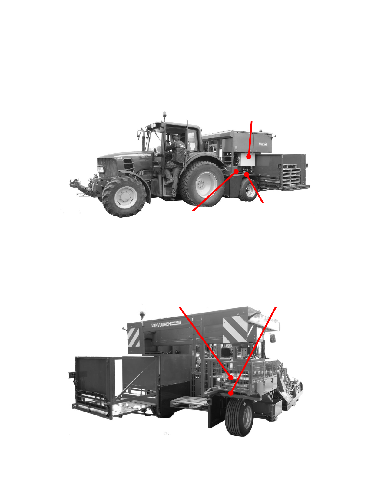
A shoe is mounted on front of the Turftick sod harvester which can move freely in all
directions. A spring pulls the shoe against the sod edge. The shoe will follow the sod edge.
If the tractor steers too much to the left, the spring will pull the shoe to the right side until it
follows the sod edge again. The movement which the shoe makes, is being read by the shoe
sensor. The control unit sends the necessary output to the steering cylinder of the front wheels
of the tractor. The (right) tractor wheel sensor is monitoring the amount of steering and will
stop the wheels from steering when it has reached its targeted angle. At the same time the rear
wheels are steering (at all times). Each trailer wheel has its own sensor and steering and
proportional valves.
WARNING
Always switch on PTO while driving. Without a running PTO the trailer wheels will
never steer!! Prevent hazardous situations which if not avoided could result in serious
injury or death.
The system usually needs to be set up only once. The procedures consist of:
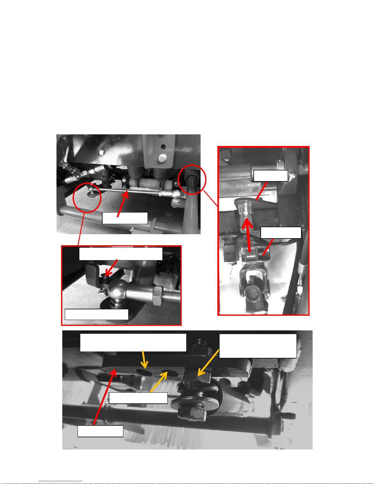
*calibrating tractor wheel sensor: while tractor wheel is steering straight, adjust sensor
position until its status LED becomes blue.
*calibrating trailer wheels: adjust trailer wheel sensors until trailer wheels are steering straight
while tractor wheels are steering straight.
*calibrating shoe sensor: adjust shoe sensor position until sod strip (left behind on field) is +/-
1 cm while ‘Offset’ button is set on 5/6. Readjust if ‘Offset’ button has too little range.
*Adjust oil pressure for Autosteer valves steering tractor front wheels.
All sensors are set up once and never needs re-adjustments, unless it is being replaced with a
new sensor. If you replace a sensor, then it needs to be calibrated again (explained further in
this manual).
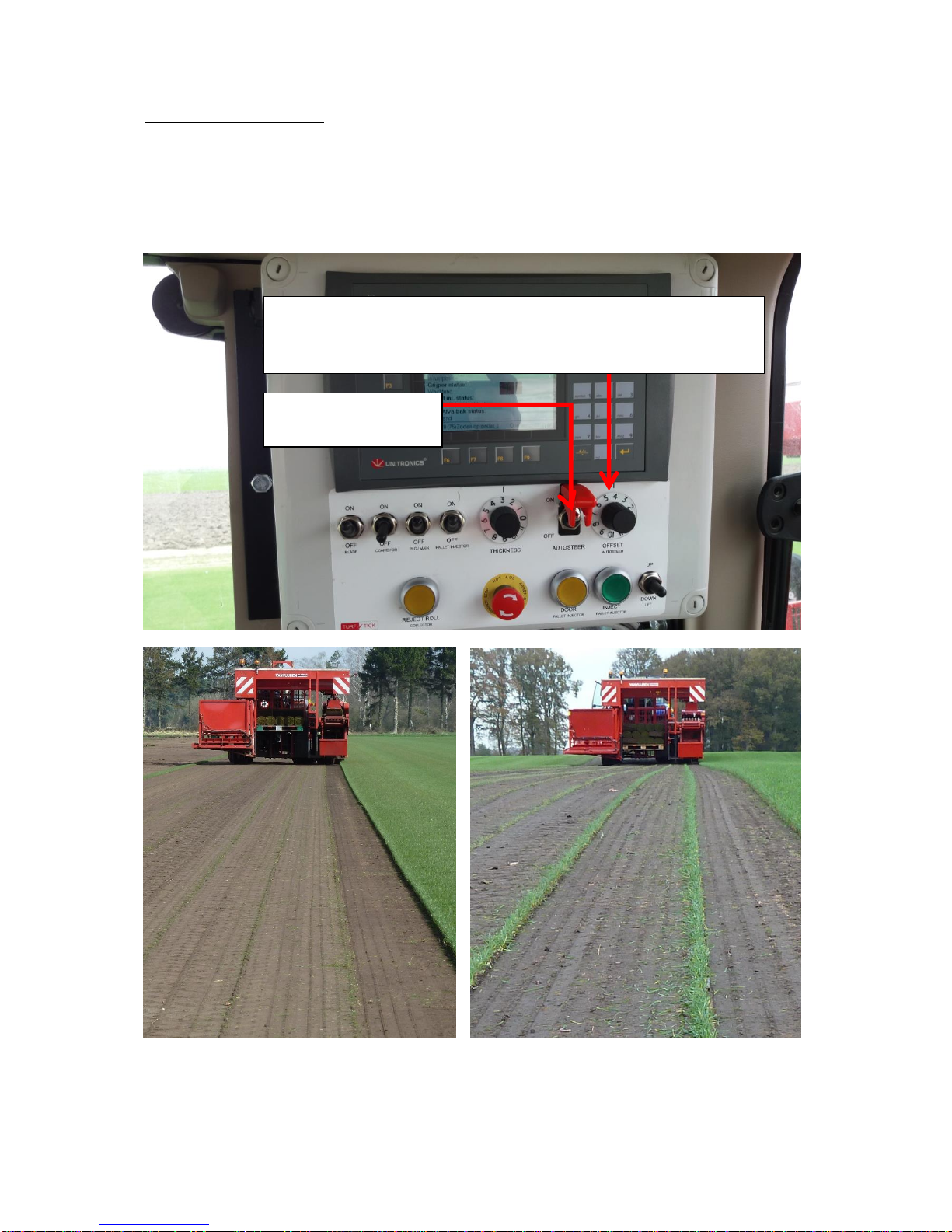
The control box has an ON/ OFF switch and an offset knob. This offset knob will regulate the
width of the sod edge which the sod harvester will leave behind while harvesting. If the range
of the offset is not properly set, adjustment of the shoe sensor can change the offset range.

6
Autosteer: OFFSET knob
It is possible to make fine adjustments to the Autosteer from the cabin. Turning the knob on
the Autosteer control box regulates the offset. As shown in the pictures below, it’s possible to
regulate the amount of sod strip left behind.
Little/ no sod strip left behind.
Big sod strip left behind.
OFFSET knob:
Used for leaving little up to big sod strip behind on field.
Position 5/6 is used as center position for sensor set-up Autosteer
system.
Autosteer ON/OFF
switch

7
4. The mechanical parts
The mechanical part of the system consists of a construction mounted at the front of the Sod
machine. The most important part of this construction is the so called “Shoe” or “Foot” that
floats over the soil and is slightly pushed (by a spring) to the sod edge.
The shoe can be lifted by a little hydraulic cylinder. This hydraulic cylinder is not operated
electronic-hydraulic, but by the standard hydraulic-connection at the backside of each tractor.
Exploded view of the mechanical part of the Autosteer system.

8
Mounting “Autosteer” mechanical parts
The ‘joint footplate’ (partsbook 101-57-52) needs to be bolted on the frame. Connect swing
arm on its joint using the quick release system. Connect ‘sensor rod’ (partsbook 101-57-14) to
both the ‘sensor guide’ (partsbook 101-57-8) and the ‘swing arm’ (partsbook 101-57-07 / 54).
The sensor rod will activate the sensor when the swingarm is moving left or right. The sensor
has to follow the movement of the swing arm.
There is a spring (partsbook 101-57-17) for which the spring tension is adjustable. The
position more to the outside (the side closest to the grass) provides more spring tension. The
position more to the inside (away from the grass side) provides less spring tension.
101-57-14
Adjustable spring tension for shoe
Front view 101-57-08
101-57-52
Quick release
soft spring tensionshoe will push less
against sod edge.
medium spring tension
hard spring tension
shoe will push harder against
sod edge. Typical setting.
101-57-08

9
Adjust the centerplate (partsbook 101-57-04) by moving it far enough to the tractor, so the
swingarm will not collide with the front brush when the Autosteer is lifted. When the
autosteer is lifted it will center in part 101-57-04 (as showed above with the dashed line). Also
make sure that the autosteer (swingarm) can move freely when the centerplate is lowered
when the Autosteer is in working mode. It should be able to move freely.
101-57-04
Make sure the swingarm does not
collide with the front brush when lifted.
Centerline (dashed) of the centerplate.
Adjusting its position determines free moving
of swingarm without colliding against brush.

10
4. Hydraulics: steering system tractor wheels

11
The system function as follows:
When the autosteer-system is not activated, the oil from the steering pump is sent through the
selector-valve (V1) to the steering-orbitrol. When the steering-wheel of the orbitrol is turned,
then oil is sent to the steering cylinder and the steering-wheels will turn. In the original
steering-system of the tractor (before the autosteer-system was mounted), the maximum
pressure of the steering system is set by a pressure relief valve. Sometimes this pressure relief
valve is mounted at the steering pump, sometimes at the orbitrol.
The pressure relief valve O1 of the autosteer system has to be set at approximately the same
value as the original pressure relief valve of the tractor (depending of the tractor will this be
approx. 140 –190 bar)
When the autosteer-system is activated the selector-valve V1 is switched so that the oil is
pumped to the bidirectional valve V2. When valve V2 is not activated all the oil is guided
back to the reservoir. The hydraulic pressure will be near to 0 bar. For some orbitrols it is
necessary to block the way between the steering cylinder and the orbitrol when the autosteer is
activated. This is done by the valves V3. These valves are simultaneously switched with valve
V1.
When the bidirectional valve V2 is activated (by the electronics of the steering-unit) than the
oil will be guided to the steering cylinder via a resistance (1 mm in diameter) so that the
cylinder will move very slowly. The maximum pressure is configured by the pressure relief
valve O2. Because of the resistance (of 1mm) most of the oil will be guided via this pressure
relief valve back to the reservoir.
It is very important to configure pressure relief valve O2 as low as possible (somewhere
between 50 and 100 bar). Reason for this is that the lower the steering-pressure is the lower is
the heating of hydraulic oil during steering by the autosteer-system. When the relief valve is
configured too low, then the steering-wheels won’t turn during steering by the autosteer-
system.

12
5. Electronic scheme

13
PCB layout
Trailer Left
sensor
Trailer Right
sensor
Tractor
wheel
sensor
Offset
button
controlbox
Tractor Wheels
Steering valve B direction
Trailer Left
Steering valve A direction
Trailer Left
Steering valve B direction
Trailer Left
Prop. Speed valve
Trailer Right
Steering valve A direction
Trailer Right
Prop. Speed valve
Trailer Right
Steering valve B direction
Tractor Wheels
Steering valve A direction
Shoe
Turftick
sensor
Status LED
RED < 2.5V
BLUE =2.5V
GREEN >2.5V

14
Active area sensors
In total there are 4 (hall-effect rotary position) sensors used for Autosteer. All have the same
measuring area (120). As you can see the sensor measures between 0.5V (-60) and 4.5V
(60). Center position (0) measures 2.5V.
This sensor has continuous rotation. This means it can move 360without being mechanically
blocked. However, it only measures over an angle of 120.
If the sensor is out of reach (inactive area), the signal output stays 0.5V or 4.5V.
The active area is when the signal from the sensor changes from 0.5 to 4.5V.
Schematic view of active and inactive areas of Autosteer sensors

15
6. Installing of the system
To mount the autosteer system correct to the tractor follow the next steps:
1. Mount the mechanical part
2. Mount the hydraulic part
3. Mount the electronic part
4. Adjust the sensors
5. Adjust the hydraulic relief valve
7. Adjusting the sensors of the autosteer
For a correct functioning of the Autosteer system it is very important that all sensors are
adjusted correctly. Summary of the set up procedure:
1. Calibrate tractor wheel sensor.
-steer tractor wheels straight.
-loosen hose clamp of tractor wheel sensor.
-adjust sensor position until its corresponding status LED turns blue.
-fasten hose clamp.
2. Set left trailer wheel straight (make sure PTO is running).
-loosen hose clamp of left trailer wheel.
-adjust sensor position until left wheel is steering straight.
-fasten hose clamp.
3. Set right trailer wheel straight (make sure PTO is running).
-loosen hose clamp of right trailer wheel.
-adjust sensor position until right wheel is steering straight.
-fasten hose clamp.
4. Align Autosteer shoe in straight line as if it is following the sod edge.
-switch Autosteer to ‘ON’.
-set ‘offset’ knob on control box on ‘5/6’ (center position).
Note: tractor wheels will react if you change the ‘offset’ button value
-loosen hose clamp of shoe sensor.
-adjust shoe sensor position until tractor wheels are steering straight again.
5. Test Autosteer on field. If the ‘offset’ button needs to be adjusted too much, then
readjust shoe sensor again, until the ‘offset’ button has enough fine adjustment in both
directions.

16
7.1 Adjusting procedure: right side wheel sensor tractor
Before you adjust the sensors:
1. Connect the right side wheel sensor on tractor.
2. Connect the sensor on TurfTick.
3. Turn ‘ON’the electrics of the tractor.
Adjusting the wheel sensor: calibrate center position
4. Make sure that the wheels of the tractor are steering straight forward.
5. Loosen the hose bracket of the right side wheel sensor al little bit, so that the sensor
can be rotated. Rotate the sensor until its corresponding status LED turns blue on the
PCB (see picture below).
6. Fasten hose clamp.
The wheel sensor is connected on the top side of the PCB (see marked connection below).
Each sensor input connector has a LED which can show 3 different colors. The different
colors indicate in which active area the sensor is measuring. We use this information to
calibrate only the tractor wheel sensor. We want to set the tractor wheel sensor at 2.5V (BLUE
LED color) when the tractor wheels are steering straight. Explanation of LED color for each
sensor input:
*RED = measuring area lower than 2.5V (steering left left)
*BLUE = measuring signal is 2.5V (steering straight)
*GREEN = measuring area above 2.5V (steering reght)
Tractor wheel sensor: while tractor wheels are steering
straight, this LED color should turn BLUE.

17
7. Verify that the wire of the sensor is coming out in a save direction; that means in the
direction of the tractor (see figure).
This sensor has an active measuring area of 120
. The measuring area can be changed
by loosening the hose clamp and rotating the sensor position.
7.2 Adjusting procedure: shoe sensor
Adjusting Shoe sensor
This sensor is mounted on the TurfTick and is measuring the movements of the Autosteer
Shoe. This sensor has an active measuring area of 120. When the sensor is out of its
measuring area, the measuring value won’t change when rotating the sensor and the autosteer
won’t work correct.
8. Make sure that the wheel sensor is already adjusted AND offset knob is in the middle
position (5/6). (Follow step 1 –7).
Sensor + guard
Tractor wheel
cable

18
9. Turn ON the engine of the tractor and make sure the electrics of the autosteer are
switched ON.
10. Align autosteer shoe with main roll by placing it in position as if it was following the
sod edge in a straight line (as shown below).
Right side shoe (partsbook 101-57-13) should be in a straight line with left side main roll
(partsbook 100-57-06).
11. While holding Autosteer shoe (partsbook 101-57-13) in position, loosen hose clamp
shoe sensor.
12. Rotate shoe sensor until tractor wheels are steering straight again.
13. Tighten hose bracket shoe sensor again

19
7.3 Adjusting procedure: left side trailer
14. Connect the left trailer wheel sensor
15. Make sure that the direction of front wheels of the tractor is straight forward.
16. Turn ON tractor and PTO. (Without a running PTO the trailer wheels will not steer).
17. Loosen hose clamp.
18. Rotate sensor until left trailer wheel is steering straight.
19. Fasten clamp hose.
7.4 Adjusting procedure: right side trailer
20. Connect the right trailer wheel sensor
21. Make sure that the direction of front wheels of the tractor is straight forward.
22. Turn ON tractor and PTO. (Without a running PTO the trailer wheels will not steer).
23. Loosen hose clamp.
24. Rotate sensor until right trailer wheel is steering straight.
25. Fasten clamp hose.
Table of contents
Popular Lawn And Garden Equipment manuals by other brands

Stiga
Stiga SD 98 Series Operator's manual

Agri-Fab
Agri-Fab H.D. Lawn Roller 45-02164 owner's manual

Harbor Freight Tools
Harbor Freight Tools One Stop Gardens 92151 Assembly & operating instructions

KHIND
KHIND IK610 instruction manual

Efco
Efco PTX 2710 Operator's instruction manual

Leafield Environmental
Leafield Environmental Litter Bin Installation guidelines

Powermate
Powermate PFTT140 Operator's manual

Coopers of Stortford
Coopers of Stortford Gainsborough Garden Shed Instructions for use

Gardena
Gardena 2650 Assembly instructions

Stratco
Stratco HOMESHEDS Assembly instructions

Cub Cadet
Cub Cadet CS 552 manual

Rowlinson Garden Products
Rowlinson Garden Products Shiplap Patio Chest Assembly instructions