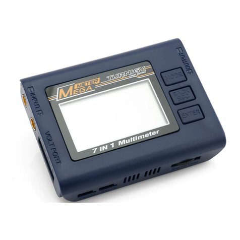
Turnigy Mega Meter User manual

INSTRUCTIONMANUAL
Multimeter
7IN 1

TABLE
OFCONTENTS
|
TABLEOFCONTENTS|
!*#'*/V?'
Introduction 03
Features 04
SetContents 04
BatteryChecker 06
BatteryInternalResistance 08
WattMeter 10
ServoTester 12
Tacheometer
RPM
13
Temperature 14
ThrustCalculator 15
ProductSpecifications 16
Warranty
And
Service 16
/!\N - Beforeyoustart
This
isa
sophisticatedunitwhichwill
bean
importanttool
in
your
electricpoweredmodelprogram.Please
be
carefulwith
it!And
please
readthisinstructionmanualthoroughlybeforeoperating.
Do
not
disassemble,modify
or
subject
the
unit
to
forceimpact.
Keep
the
MegaMeterwellawayfromdirt
or
water.
Highpowerelectricalsystemsposedangersindependent
of
devices
like
the
MegaMeter
anditisthe
user'sresponsibility
tobe
familiarwith
thesedangers
and
take
any
necessaryaction
to
ensuresafe
use.
Shorting
a
rechargeablebattery
ora
MegaMeterconnected
toa
rechargeablebattery
or
batterycharger
can
supplyhugecurrents
and
haveseriousconsequencesincludingexplosions,causingfire,damage
toequipment
and
personalinjury.
There
are
risksassociatedwith
the
potentiallyhighcurrentsmeasured
by
the
MegaMeter.Theseinclude,
butarenot
limited
to,
fire,burns
andpersonalinjury.
The
usermust
be
familiarwith
the
relevantmeth-
ods,
procedures
and
connectioncomponentsbeforeusing
or
making
anyconnection.
Do
not
exceed
a
maximum
of60
volts
forthe
mainpowerpack
(MPP)
Keepproperdistancefrompropellerduringmeasurementprocess.
INTRODUCTION
INTRODUCTION
Thank
youforthe
purchase
of
thisTurnigyMegaMeter.
The
Turnigy
MegaMeter
can
carry
outan
enormousrange
of
functionsrelated
to
ElectricPoweredmodels
andhas
beendesignedwithease
ofuseas
aprimeobjective.ThisInstructionManualdescribes
the
scope
of
MegaMeter
andhowto
make
it
work
foryou.
Input
Voltage
'Port LCDDisplay
DotMatrix128*64
Connector
to
Temperature
SensorProbe
Mode
Connector
to
Servo
PotentiometerDial
toControlServos,
ESC,
other
PW
devices
Output
.Optical
Tachometer
Sensor
Enter

FEATURES
FEATURES
1.
BatteryChecker
2.
BatteryInternalResistance
3.WattMeter
4.
ServoTester
5.OpticalTachometer
6.TemperatureGauge
7.ThrustCalculator
SET
CONTENTS
1.
InputCable
4.
2.
BatteryInternalResistanceCable
5.
3.MegaMeter
TemperatureProbe
OutputCable
FEATURES
TheMainscreendisplays
allthe
availablefunctions.
The
desired
function
canbe
accessed
by
highlighting
the
desiredfunction
by
pressing'MODE'button,pressing
the
'ENTER'button
to
select
thatfunction.
INT
RESI
STftNC
E
WATTH
E T E R
SERUOTESTER
TACHOMETER
RPM
TEMPERATURE
THRUSTCfiLC.
. .
SET
UP
BATTER
V CHE
C
KER
iraiiRiHimi
HiiTTMETE
R
SERUOTESTER
TACHOMETER
RPM
TEMPERATURE
THRUSTCALC...
SET
UP
BATTERYCHECKER
INT.RESISTANCE
HATTMETER
SERUOTESTER
TACHOMETER
RPM
TEMPERATURE
THRUSTCALC.
. .
BATTERYCHECKER
INT.RESISTANCE
HATTMETER
SERUOTESTER
TACHOMETER
RPM
TEMPERATURE
napm
SET
UP
BATTERYCHECKER
INT
.
RESISTAN
C E
SERUOTESTER
TACHOMETER
RPM
TEMPERATURE
THRUSTCALC...
SET
U P
BATTER
Y
CHECKER
INT.RESISTANCE
HATTMETER
SERUOTESTER
T
A
C H
0
METER
RP
M
Hdiijjiiaiiisia
THRUSTCALC...
SET
U P
BATTERYCHECKER
INT.RESISTANCE
HATTMETER
TACHOMETER
RPM
TEMPERATURE
THRUSTCALC...
SET
U
P
BATTERYCHECKER
INT.RESISTANCE
HATTMETER
SERUOTESTER
naaaaflamaaa
TEMPERATURE
THRUSTCALC...
SET
UP

BATTERY
CHECKER
BATTERY
CHECKER
TheMegaMeterallowsyoutochecktheindividualcellvoltagesofa 2
cells-8cellsLithiumbattery.TheMegaMeterindividuallymeasures&
diagnosesthecellvoltagesofthemultiplecells,theresultisdisplayed
onthelargeliquidcrystalscreen.TheMegaMeterreplacesallofthe
tediousmeasurementandcalculationsrequiredinthepasttodetermine
theoverallvoltageoftheLiPo,LiFe& Lilonpackandtheindividualcell
voltagesthatdeterminethebalanceoftheLithiumpack.
TheMegaMeternowmakesitpossibletodetermineandverifythe
detailedstateoftheLithiumbattery.
Abalancedbatteryprovidesa saferenvironmentwhenflying.Ifyou
knowthatyourcellbalanceisoutyoucanaddresstheissue.
Thepreventionofdeterioratingcellsovertime,willimprovethe
efficiencyandstabilityoftheLithiumbattery.
WhenyouconnectthebalanceleadtotheMegaMeteryoumust
ensurethatboththeGroundpin'sforthebalanceconnectorandthe
MegaMeter
gotogether.DifferentBalanceleadshavedifferentwiringconfigurations
andsomearecolored.
TheMegaMeterhas2.54mmpinintervals.Iftheconnectoronyou
batterydoesnotfitdonotforcetheconnector,obtaina suitablead-
aptorleadfromyourhobbyshop.
Battery
Connection
Diagram
BATTERY
CHECKER
•Connectthebalanceleadto'VOLTPORT'
•Press'ENTER'toentermainfunctionscreen
•Press'ENTER'toselectBATTERYCHECKERfunction
•Press'MODE'toselectbatterytype
•Press'ENTER'toconfirmbatterytype
Battery
Type
Number
of
Cells
Serial
Pack
Voltage
)
Remaining
Amount%
Balance
Status
%
LiPo -8
5 23 . 15 9 U
•i:i3 .
SH -i 25 3 .8 H 7!
'353.
S5
2 H53 .8 5 91
S5 3 .
0-7
7 65 3 .8781
175 8 8:>(.
57
69K E1
57
69K
K
1
i
Individual
Cell
Voltage
S31
yL ;;<;!
Balance
Gauge
The
Highest
Cell
Voltage
Lowest
Cell
Voltage!
i
Cell
Voltage
Differential
Serial
voltage
Packvoltageofthewholebattery(totalvoltageofallcells)isindicated
The
number of
serial
cells
Thetotalnumberofcellsinthebatterypackisindicated(6Sasindicatec
inthepicture6 serialcells).Thisisthesameasthecellquantity.
Remaining
amount fuel
gauge
Theremainingamountgaugegivesyoua graphicalbargraphdisplay
ofthestatusofthebatterybygraphandthebalanceofthecellsby
graph.
Whenthebatteryisfullychargedthegraphextendsto"F"on
theright handsideoftheLCD.Asintheexampleyoucanseethatthe
batteryisabout50%used.Therearetimeswhendifferencesoccur
betweentheremainingamountandtheactualremainingamount.
Thesedifferencescanbeassociatedwiththequalityanduseofthe
batteryanditscells.A batterythathasalwaysbeenchargedwitha
reputablebalancerislikelytoreproduceaccuratereadingsonthe
MegaMeter.A batterythathashada hardlifefulldischargeandre-
chargewithnobalancechargingismorelikelytohavediscrepancies
betweenactualandshownresults.
Cell
balance
gauge
TheCellbalancegaugemeasuresthedifferencebetweenallcellsthat
areconnectedtotheMegaMeter.

BATTERY
INTERNALRESISTANCE
BATTERY
INTERNALRESISTANCE
Thedifference
is
showngraphicallybetween
the
cellthat
is
showing
thehighestcellvoltage
tothe
cellthat
is
showing
the
lowestcellvoltage
(largestcellvoltagedifference)indicated
onthe
graph.When
the
cell
voltagesreadequal,
thebar
extends
allthewaytothe
right
(O).
This
indicatesthat
the
cells
areall
balanced
toa
satisfactorylevel.When
thecellshave
a
difference
in
voltage
thebar
shortens
and
indicates
towards
the
left
(X).In
order
to
maintainlonglastingbatterylife
ifthe
balancegaugedoes
not
show
a
satisfactorycellbalancethen
a
cell
balancershould
be
applied
tothe
packbefore
use.Ifthe
cellbalance
indication
islow
after
the
battery
has
beenusedthis
canbe
normal
and
chargingshouldoccurwith
a
balancecharger.
BATTERY
INTERNALRESISTANCE
TheMegaMeter
has
beencreated
to
give
youthe
ability
to
make
aninformeddetermination
of
what
the
truecell
and
packratings
byproviding
a
usefulmeasure,
the
cellinternalresistance.
•Connectbattery
to
MegaMeter
via
VoltagePort
to
power
onthe
•MegaMeterUsingsuppliedcable(pitch2.54mm)
to
measure
indi-
vidualinternalresistance
•PressMODE'
to
select
'INT.
RESISTANCE'function
•Press'ENTER'
to
confirmselection
ConnectionDiagram
for
Measurement
of
Battery
InternalResistance
Once
we
have
an
idea
ofthe
internalresistance
ofa
cell
wecan
then
usethat
to
determine
how
efficient
our
powersetup
isas
well
as
knowing
how
muchpower
is
beingturned
to
heat
inthe
batterypack
andadditionallyknow
how
much
the
voltage
can
potentiallydropunder
load.
BATTERYCHECKER
•mSHECBl
Int
.Resistance
WATTMETER
SERUOTESTER
Res:33noh
TACHOMETER
RPM
TEMPERATURE
THRUSTCALC...
SET
UP
Let
itbe
statedthatthere
isno
perfecttest
for
cellinternalresistance.
Due
tothe
nature
of
batteries,cellsexhibitcharacteristics
of
resistance
capacitance
and
inductance
of
which
all
contribute
tothe
measured
internalresistance.Internalresistance
can
varyconsiderablyeven
within
the
same
cell,
thismakes
the
task
of
determining
the
internal
resistance
a lot
harder.
Factorseffectingresistancereadings:
Contact
corrosion
While
not
actuallypart
ofthe
cellitself,havingdirtycontacts
tothe
cells
canmake
a
noticeabledifference
inthe
resistance.Wipingclean
the
contacts
can
improvecontactresistance
by10or
moremilliohms.
Cell
temperature
Formanycellchemistries
the
resistance
ofthe
packdecreasesinitially
fromroomtemperature
toa
certainlevel(perhaps
45C)
afterwhich
the
resistance
ofthe
packwillincreaseagain.Lithiumcells
in
particular
sufferpoorcellresistancenear
OC.
Cell
charge
Generally
the
closer
toa
fullcharge
a
cell
isthe
lower
the
internal
resistance.
Cell
age
Ascellsbecomeoldertheirinternalresistancetends
to
increase.
TheMegaMeter
has
beenbuilt
to
allowcells
tobe
testedunder
a
known
setof
loadswhichwillfacilitatecomparisons.
-
09-

WATT
METER
WATT
METER
PRECAUTIONS
1.
Donot
leave
a
cellconnected
tothe
MegaMeter
for
morethanfive
minutes.
2.
Be
awarethatalthough
the
MegaMeteronlytakessmallsamples
from
thebatterypack,
the
voltagewill
be
reduced.Makesure
you
check
yourpackbalance.
3.Avoidplugging
the
cell
in
reversepolarity.
The
MegaMeter
can
copewith
areversedconnection
fora
few
seconds
butit's
stillbetter
not
todo
it
in
the
firstplace.
WATT
METER
ThisfunctionmeasuresCurrent(Amps),Peakcurrent,Voltage(Volts),
Power(Watts),Energy(Watt-Hours)
and
Charge(Amp-Hours)values
for
you,
in
real-time,
for
the
circuit
in
which
you
connect
it.
Speed
Motor
•1—
3
1
H
•
Controller
MegaMeter
is
activatedwhen
the
battery
is
connected
to
the
unit.
•Press'MODE'
to
select'WATTMETER'function
•Press'ENTER'
to
confirmselection
Now
youcan
stopwonderingwhat'sgoing
on
withyourelectricmodel
and
get
answersthatallow
you
to
applyscience
to
yourhobby.
The
precisemeasurements
you
collectwillhelp
you
finetuneyourmodel
to
get
allthe
performancethat
you
paid
for.
Withwattmeterfunction,
itis
now
easy
to
determinethingslike:
•Flighttime
•Currentthrough
an
ESCand
motor
•
ESC,BECand
motorefficiencies
•Charge
put
into
and
removedfrom
a
battery
and
the
performance
of
batterychargers
•Batteryhealth
•
Why
power
is
lostduringacrobatics
or
extremeconditions
•Effect
of
gearing
and
propellersize
and
shape
on
powerconsumption
andbatterycurrents
•Effects
of
modifications,
ageand
damage
on
manyelectricalsystem
components
•Cleverhobbyistswilldiscover
new
applications
to
furtherimprove
electricmodelperformance.
Thefollowing
are
someexamples
of
meterconnections.Manyother
arrangements
and
uses
are
possible
Testing
Loads
(e.g.
motors)
WATT
METER
Battery
Pack
CURRENT:^.
3
5.11ft
PEAK
CC
'j.i.
52.
lift
U
DL.TftGE
:
25.13
U
N-ftTTflGE
:
882
.
3
1
M
P
E
fl
K(H
)
:
13
6
3.
2
M
Energy:
8 2 N h
Speed
Controller
Battery
Pack
CURRENT:^.
3
5.11ft
PEAK
CC
'j.i.
52.
lift
U
DL.TftGE
:
25.13
U
N-ftTTflGE
:
882
.
3
1
M
P
E
fl
K(H
)
:
13
6
3.
2
M
Energy:
8 2 N h
Speed
Controller
Battery
Pack
CURRENT:^.
3
5.11ft
PEAK
CC
'j.i.
52.
lift
U
DL.TftGE
:
25.13
U
N-ftTTflGE
:
882
.
3
1
M
P
E
fl
K(H
)
:
13
6
3.
2
M
Energy:
8 2 N h
Speed
Controller
CURRENT:^.
3
5.11ft
PEAK
CC
'j.i.
52.
lift
U
DL.TftGE
:
25.13
U
N-ftTTflGE
:
882
.
3
1
M
P
E
fl
K(H
)
:
13
6
3.
2
M
Energy:
8 2 N h
Motor
Battery
on
SOURCEside,ElectronicSpeedController
(ESC)and
motor
on
LOADside,with
ESCon,
the
metershows
the
currentinto
the
motor,voltage
and
power
at
the
battery
and
accumulates
the
charge
(Ah)while
the
motor
is
running.
Battery Charging
Battery
Charger
HATT
METER
CURRENT:
3 5
.
1 1 A
Battery
Battery
Charger
PEAK
CO:
52
.
1 ifl
UOLTfiSE:
2
5'.
i3
U
Battery
Battery
Charger
WATTftGE:
S S 2
.SIM
P
%
ftK<H>:
13@3.
2 H
Energy
32Hh
Charge.
3
.
2 Ah
Battery
WATTftGE:
S S 2
.SIM
P
%
ftK<H>:
13@3.
2 H
Energy
32Hh
Charge.
3
.
2 Ah
With
a
batterycharger
onthe
SOURCEside
and
batterypack
onthe
LOADside,
the
metershows
the
chargingcurrentinto
the
battery,
the
voltage
and
chargingpower
at
the
battery
and
accumulates
the
charge
(Ah)into
the
battery.
Battery Discharging
Battery
Pack
CURRENT
PEKKCc
y•
UQL
TftGE:
H
ft
T T
ft
6
E
Discharge
Load
When
the
battery
is
discharged,
the
meterindicates
the
totalcharge
(Ah)
the
batterydelivered
to
the
load
as
well
as
current,voltage
and
dischargingpower.

SERVOTESTER
TACHEOMETER
RPM
Receiver
&
Servo
Testing
Battery
Pack
U0 L T A G E
WATTAGE
PEftKCH)
Reciver
Servo1
Servon.
SERVOTESTER
Servotesters
are
veryuseful
for
exercisingyourservos
and
Electronic
SpeedControl
(ESC)
without
the
need
to
turn
on
yourtransmitter,
and
you
donot
evenneedyourreceiver.
The
servotesterwill
putouta
signaljustlike
the
signalsnormallysent
by
yourreceiver
tothe
servos
or
ESC.The
dialknob
onthe
servotesterwillchange
the
signaljust
likemovingyourtransmitterstickwouldchange
the
signalgoing
toa
servo
orESC.
Tousethetestertoevaluatea servo
Connecting
a
battery
tothe
i-Meter
voltport.Plug
a
servointo
the
servoport.
The
servo
canbe
controlledwith
the
adjustmentdialunder
ManualMode.Press'MODE'buttononce
tosetthePPM
signal
to
auto.
Theservotesterwill
use
1520us
as
centre
and
automaticallyoutput
cyclingsignal
to
move
the
servo
arm
back
and
forward.
TousetheServoTestertooperateanESCandmotor
Connecting
a
battery
tothe
MegaMetervoltport.Anotherplugconnec-
ted
tothe
ServoTester
isthe
plugfrom
theESC
thatnormallygoes
to
thereceiver.Connect
theESCto
motorleads.When
you
connect
the
battery
totheESCit
willpower
up.It
shouldreact
the
same
way
doeswhenpowered
up
using
the
radiogearwith
the
throttlestick
in
theminimumpowerposition.
Youcannow
spin
upthe
motor
by
turning
theservotesterknob.
No
receiver
or
transmitter
is
needed.This
isa
great
wayto
testmotors
onthe
bench.
TACHEOMETER
RPM
There
isan
opticaltachometerwithinMegaMeter.
An
opticaltacho
sensor
is
fitted
tothe
rightsideMegaMetercase
andis
activated
by
pointingMegaMetertowards
the
propeller
ata
distance
of10and
20cm
from
the
propeller.
•Connectbattery
to
MegaMeter
via
VoltagePort
to
power
onthe
•MegaMeterPress'MODE'
to
select"TACHOMETER
RPM"
•Press'ENTER'
to
confirm
the
function
•Press'MODE'again
to
change
the
range
of1-5
blades
•Press'ENTER'
to
start
RPM
measurement
Thefluctuatinglightcaused
bythe
rotation
ofthe
propeller
is
sensed
andcountedover
a
period
of
either
1 or2
seconds.Allow
a
couple
of
seconds
for
readings
to
steady.
With
a
gearedmotor,
the
motor
RPM
willnormally
be
higherthan
the
prop.
RPM,butitisthe
prop
rpm
which
is
beingmeasured
and
quoted,
so
the
gearratio
isnot
reallyrelevant.

TEMPERATURE
PleaseDON'T
use
opticaltachometerwithfluorescentlightingwhich
willgivefalsereadings,such
as
3000
or
3600
rpm.
Theoptical
RPM
sensorwillfunctionover
a
largerange
of
propeller
sizes,
RPMand
lightingconditions.
Ithas
evenable
to
measure40mm
diametermodelboatpropsspinning
intheair.
Experimentwithdifferent
sensorpositions.
In
somecases,bestresults
maybe
achieved
by
testing
inthe
shade.With
the
motorrunning,move
the
opticalsensor
toabout
10-20cm
from
the
propellers,taking
alldue
care.Small
propellers
may
requirecloserpositioning.
The
number
of
propeller
bladesshouldalso
beset.
Wrongsettingwillaffect
RPM
readings
for
theopticaltachometer.
For
example,fitting
a
threebladedpropellers,
butleaving
the
i-Meter
bladefigure
at2
wouldcause
the
optical
tachometer
to
read
50%
high.
TEMPERATURE
There
isa
temperaturesensoravailable,
soyoucan
monitor
the
temperature
of
battery,motor,electronicspeedcontroller,
etc.
When
nosensor
is
connected,displaywillindicate0.0°C
and
32°F
•Connecttemperatureprobe
to
MegaMeter
•Press'MODE'
to
select"TEMPERATURE"
•Press"ENTER"
to
confirmselection
Cc
Current
Temperature
Celsius
TEMPERATURE
Current
Current
Temperature
Fahrenheit
89
F
Peak
122F
PeakValue
Celsius
:
PeakValue
Fahrenheit
THRUSTCALCULATOR
m
RUST
CALCULATOR
Thethrustcalculator
can
estimate
the
thrust
ofan
airplane,there
are
manyvariances
and
someknownfactors.
Letsassume
we
have
an
airplane
and
this
isits
firstflight.
We
know
the
size
ofthe
propeller
andwecandoa
staticfullthrottle
rpm
checkwith
a
tachometer
onthe
ground.
Wecannowadd
theseknownfiguresinto
ThrustCalculator.
Bythe
factthat
youcan
verifythrust
it
becomes
possible,
to
estimate
the
generalpower
ofthe
airplane
in
advance.
Thiswillgive
you
moreknowledgeaboutyourplane
andthe
power
characteristics
to
makeyourfirstflightlesschallenging
and
safe,after
all
youmay
haveotherflightcharacteristics
to
deal
with.
Thisshould
help
youto
estimateflighttake
off
distances,recoveryfrom
a
stall.
For
moreexperiencedpilotsthiswillenablethem
to
calculate
ifthe
plane
is
going
tobe
able
to
hover.
Itcan
show
you
whatchanges
tothe
power
calculationwill
be
affected
bya
differentsizepropeller.
Propeller
Length(inch);
THRUSTCALC
^propeller's
Effectiveness;
[Coefficient
j
Propeller
Revolution
j
RPM
(Revolutions
Per
Minute)
j
'D
i
oneter
CF
:
Blades:
RPM
:
Thrust:
0
10.00
1
.00
2
'
110
0 0
Number
ofBlades
1
.
3
.
E
5 3
K
9
H
2
H
L b
CF(Propeller'sEffectivenessCoefficientTable)
Manufacturer CF
Standardpropeller 1.00
APCpropeller 1.06
APC
SF
1.50
APC
W
propeller 1.09
MenzSpropeller 1.03
Bambulapropeller 1.02
Bollyclubman 1.04
Cox 1.10
GWS
HD
0.75
GWS
RS(SF)
1.10
Smart 1.02
ZingerWood 1.00
15

PRODUCTSPECIFICATIONS
Thestaticthrustcalculation
is
takenfrom
the
October
86AMA
magazine,
airdensity
is
based
on
29.92
inHg,and
propellerpitch
isnot
used
in
this
calculation.Practicaltestsrevealedverylittle
ifany
change
in
thrust
due
topitchvariation
atthe
same
RMP.
It
is
believedthatthis
is
partly
duetoany
increase
in
thrustbeingnegated
bybladestalling
anda
moreturbulentinfluxareawithincreasedpitch.
Thisobviouslyonlyapplies
to
staticconditions,
not
flyingconditions.
PRODUCTSPECIFICATIONS
•
Max
inputvoltage:
60V
•Voltagemeasurementrange:
2-8S
LiPo/LiFe/Lilon
•Voltagedisplayresolution:0.001V
•VoltPort:2.54mmpitchpins,
9
pins
•
Max
current:
100A
•Shuntresistance^.001
ohm
•Displayedresolution
A:0.01
•Temperatureresolution:
1
Celsius
/1
Fahrenheit
•
PPM
signaloutput:750uS
-
2150uS
•Number
of
propellermeasurable
: 1 to5
•Propellerrotatingrange:1-60000RPM
•Dimension:95.3x72.8x21
5mm
•
Net
Weight:
85g
WARRANTY
ANDSERVICE
Weguaranteethisproduct
tobe
free
of
manufacturing
and
assembly
defects
fora
period
ofone
yearfrom
the
time
of
purchase.
The
warranty
onlyapplies
to
material
or
operationaldefects,which
are
present
atthe
time
of
purchase.Duringthatperiod,
we
willrepair
or
replacefree
of
servicecharge
for
productsdeemeddefective
dueto
thosecauses.
Youwill
be
required
to
produceproof
of
purchase(invoice
or
receipt).
Thiswarranty
isnot
valid
forany
damage
or
subsequentdamage
arising
asa
result
of
misuse,modification
orasa
result
of
failure
to
observe
the
proceduresoutlined
in
thismanual.
Other manuals for Mega Meter
1
Table of contents
Other Turnigy Multimeter manuals