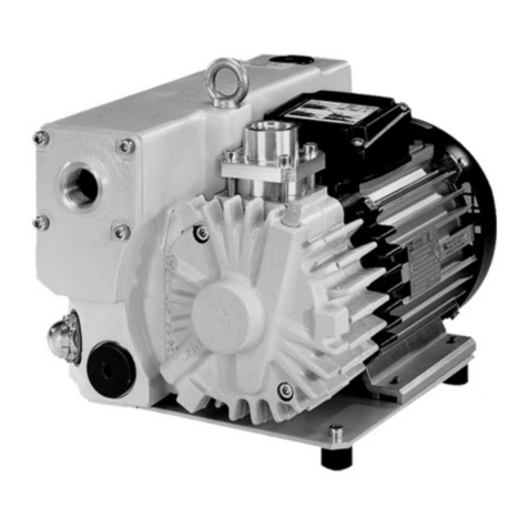
Most Tuthill C Series pumps are required to develop 25" mercury vacuum at 0 psi on
factory test. While these pumps will develop as high as 27" of vacuum, it is a sound engineering
practice to avoid extreme vacuum whenever possible. Select a pipe size to reduce line friction
loss to a minimum.
The pump should be located as close to the source of supply as conditions permit and if
possible, below the level of the liquid in the reservoir. When necessary to locate the pump in a
pit, provisions should be made to safeguard against flooding. Care must be taken to properly
support the suction and discharge piping so that no strain is put on the pump due to either
weight or expansion. Piping strain can result in misalignment, hot bearings, worn couplings, and
vibration. It is important that the piping used be clean and free of chips and scales.
Proper Installation
Unsatisfactory pump installations are usually characterized by poor suction conditions
for the specific liquid being handled. Suction conditions should be minimized to prevent
vaporization of the liquid. If vacuum conditions force the liquid to vaporize, cavitation will occur,
resulting in loss of capacity, premature wear and noisy operation.
When handling high viscosity liquids, the speed of the pump must be reduced and the
size of the lines increased to prevent cavitation.
Note: Pipeline friction increases at a rapid rate with an increase in viscosity. For a given pump
and motor, larger pipelines are necessary to maintain the same pump pressure when changing
from a thin fluid to a thick one.
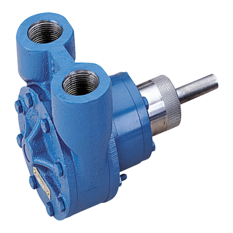
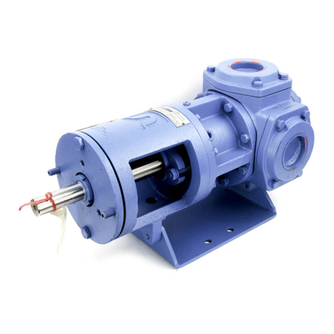
Most Tuthill C Series pumps are supplied with both ports on the same plane. Pumps with
this type of porting arrangement should always be installed with the ports facing upward to
insure proper priming. If it is necessary to install the pump with the ports pointing to either side,
it is recommended that the top port be the suction port. This will prevent gravity-induced
drainage of fluid through the suction port. When pipes are installed, an inverted "U" bend should
be incorporated into the suction line close to the pump for priming purposes.
Viewing the pump from the shaft end, the inlet port is on the right for clockwise rotation
and on the left for counter-clockwise rotation. On pumps with built in relief valves, the adjusting
screw of the valve must always be located on the suction side of the pump.
Pumps should be filled with oil at installation and should never be allowed to run dry.
Every pump installation should have a good foundation. Its structure should be
sufficiently strong to hold the pump rigid and to absorb any strain or shock that may be
encountered. The installation should be leveled, checked for proper piping alignment, and then
fastened securely.
Method of Drive
Direct drive through a traditional flexible coupling is recommended. (CC pumps are
direct driven by the motor shaft as an integral part of the pump.) However, do not expect the
flexible coupling to compensate for misalignment. Contact the coupling manufacturer to
determine the maximum amount of misalignment to which the coupling can be subjected.
All C Series pumps are directional (except CC Series without a relief valve). Rotation
must be specified at the time of order. The seal chamber communicates with the neutral zone
and therefore the seal/packing is subjected to approximately one half of the discharge pressure.
v 1.1.2 Page 4 of 16 6.13.05

