8
Other types may be too hard and transmit vibration, or too soft and may exert considerable force on the pump and piping
when collapsing under atmospheric pressure. Pour a small quantity of oil into the pump suction before connecting the
inlet piping to ensure proper lubrication at initial start-up.
Make all inlet connections vacuum tight. As a check, note that the pressure at the end of the connecting manifold should
be very close to that obtained with the pump inlet blanked-off. All demountable joints should be O-ring sealed.
If threaded connections are used, clean the threads and turn them together about two turns. Cover the remaining
exposed threads with a sealing compound such as Loctite 567 or PTFE Tape for piping up to 1” in diameter. Use Titeseal
(Radiator Specialty Company, North Carolina), on large pipe sizes. Screw the joint together tightly.
Install a vacuum isolation valve between the system and the pump with a means for connecting a vacuum gauge on
both sides of the valve and an air admittance valve on the pump side of the isolation valve. With such an arrangement,
it is possible to check either the system or the pump for leaks without disconnecting the vacuum piping. This isolation
valve will also allow the system to be kept under vacuum while the pump is not running, or the pump operating while the
system is open to atmospheric pressure.
VACUUM GAUGES
Two general types of vacuum gauges are used for the testing of vacuum equipment, total pressure reading types, such
as Thermistor or Thermocouple gauges, and partial pressure reading McLeod gauges. The McLeod gauge indicates the
partial pressure of permanent gases. It does not indicate the component of pressure due to condensable gases such
as water vapor. It is not greatly affected by vapor contamination unless the contamination pressure is quite high. It is
most useful in confirming pump performance and for determining the absence or presence of real leaks. Thermistor or
Thermocouple gauges are preferable for leak checking and indicating the degree of contamination.
A high Thermistor or Thermocouple gauge reading may indicate that the pump is contaminated, that it leaks, or both. A
high McLeod gauge reading means that a real leak is present.
ELECTRICAL CONNECTIONS
WARNING: Disconnect pump from electrical power source prior to making repairs or adjustments to any electric
component of the unit.
Check the operating voltage of the motor by comparing the lead connections with the markings on the motor. Connect
it to the proper power source through necessary switching and safety equipment. After wiring is complete, momentarily
start and stop the motor to check the direction of rotation against the arrow cast on the pump. If it rotates in the wrong
direction, switch any two wire leads to correct this problem. (These are generally printed on the connections cover
plate.) Note that standard pumps rotate clockwise when facing the pump pulley.
WARNINGS:
• When operating the pump in an enclosed area it is necessary, for health reasons, to have the area well ventilated.
If ventilation is not adequate, the pump discharge should be filtered or piped to open air.
• Do not block or restrict the flow of gas from the pump discharge. Back pressure could cause severe damage
• The belt guard must be properly secured to the pump at all times while the pump is running.
GENERAL
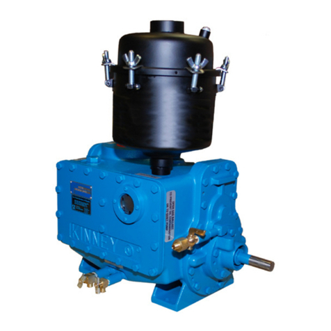
Kinney KC Model pumps are designed for low-pressure operation. They are generally not suitable for prolonged periods
of operation at high pressures. Each pump has been thoroughly tested and is ready for operation as soon as it is
installed and filled with oil. If the vacuum system is tight, including the connections to the pump, the ultimate system
pressure should be close to that obtained with the pump inlet closed off.
FILLING THE PUMP WITH OIL
Refer to the specifications chart for the quantity of oil required for the particular pump. On initial startup, pour a small
quantity of oil into the pump inlet to insure adequate lubrication on starting. Pour the remainder of the required oil
quantity into the pump as follows:
KC5/8: Unscrew the oil mist eliminator from the pump. Remove the high vacuum stage oil fill plug. Pour approximately

