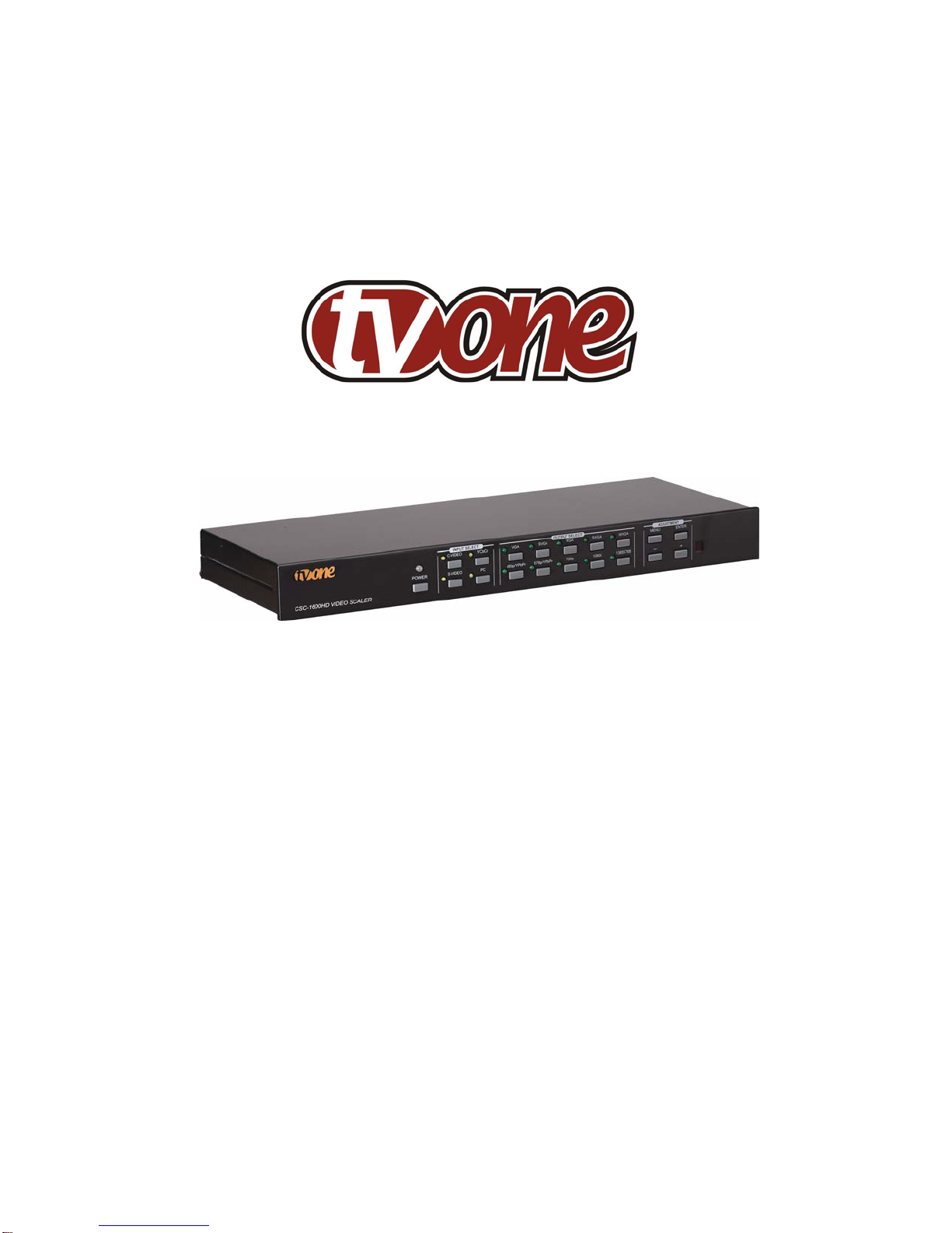
TV One Multimedia Solutions CSC-1600HD User manual

Instruction Manual
CSC-1600HD
Video Scaler

2

Table Of Contents
1.0 Introduction 4
2.0 &
3.0 Multi-Language Safety and IPR Information 6
4.0 Specifications 13
5.0 Package Contents 13
6.0 Connecting the Hardware 14
7.0 Operating The Unit 16
8.0 Troubleshooting 22
9.0 Limited Warranty 23
10.0 Regulatory Compliance 23
11.0 Contact Information 24
3

1.0 INTRODUCTION
Thanks for purchasing this CSC-1600HD Video Scaler from TV One. The CSC-1600HD
is designed to convert Composite Video, S-Video and YCbCr Component Video signals
to a variety of computer and HDTV resolutions. The unit accommodates most
worldwide NTSC, PAL and SECAM TV standards and has many features to enhance
performance. AFM (Adaptive Film Mode) is an automatic 3:2 pull-down detector that
provides clear and crisp de-interlacing video from 24 frames-per-second film. Our
professional video conversion products have been serving the industry for over twenty
years. TV One offers a full line of high quality Video Scalers, Scan Converters, Analog-
Digital (DV, SDI, DVI) Converters, Standards Converters, Digital Video Recorders,
Frame Synchronizers, Time Base Correctors, LCD Monitors, Matrix Routing Switchers
and Distribution Amplifiers.
1.1 Liability Statement
Every effort has been made to ensure that this product is free of errors. TV One cannot
be held liable for the use of this hardware or any direct or indirect consequential
damages arising from its use. It is the responsibility of the user of the hardware to check
that it is suitable for his/her requirements and that it is installed correctly. All rights
reserved. No parts of this manual may be reproduced or transmitted by any form or
means electronic or mechanical, including photocopying, recording or by any
information storage or retrieval system without the written consent of the publisher.
TV One reserves the right to revise any of its hardware and software following its policy
to modify and/or improve its products where necessary or desirable. This statement
does not affect the legal rights of the user in any way.
All third party trademarks and copyrights are recognised. The TV One logo, TV One-
task and CORIO are the registered Trademarks of TV One. All other trademarks are the
property of their respective holders.
4

1.2 FEATURES
The CSC-1600HD Video Scaler has many features that enable it to perform in a
superior manner. Among those features you will find:
•Direct Video Input Selection
•Composite, S-Video, YCbCr Component Inputs
•PC/HDTV (RGBHV-YPbPr) input for Bypass
•Individual Input Video Adjustments
•Automatic Input TV Standards Detection
•NTSC, PAL, SECAM Operation
•RGBHV Resolutions up to 1365x768
•YPbPr Output at 480p and 567p
•Output Signal Selectable on HD-15 or 5 BNC Connectors
•OSD (On Screen Display) for Menu Navigation
•RS-232 Interface and Windows Control Panel
•Infrared Remote Control
•IR and Front Panel Lockout Feature
•Desktop and Rackmount Cases
•Universal Internal Power Supply
1.3 Getting the Best Results
There are many factors affecting the quality of results when Composite, YCbCr or S-
Video signals are up-converted to computer or HDTV resolutions. Some basic
precautions will ensure the best possible performance from your Video Scaler.
•Output display device– The quality of the output signal will depend largely upon
the type and quality of display device used. For instance, some video projectors
just look better than others.
•Distance between the Video Scaler and the display device – This plays a
major role in the final result. Long distances are possible, but special measures
should be taken in order to avoid cable losses. These include using high quality
(coax-type) cables or adding line amplifiers.
•Output connection cables – Low quality cables are susceptible to interference.
They degrade signal quality due to poor matching and cause elevated noise
levels. Therefore, cables should be of the best quality. Coax-type computer
cables are recommended because of their superior internal shielding
characteristics.
•Interference from nearby electrical devices – Such devices can have an
adverse effect on signal quality. For example, an older computer monitor often
emits very high electromagnetic fields that can interfere with the performance of
video equipment in its proximity.
5

2.0 IMPORTANT SAFETY INSTRUCTIONS
To insure the best from this product, please read this manual carefully. Keep it in a safe
place for future reference.
To reduce the risk of electric shock, do not remove the cover from the unit.
No user serviceable parts inside. Refer servicing to qualified personnel.
2.1 POWER AND CONNECTIONS
This unit is not disconnected from the AC power source as long as it is connected to the
wall outlet. The off state for this unit is called standby mode. In standby mode the unit
is designed to consume a reduced quantity of power compared to normal operating
modes.
When not using the unit for a long period of time, insure that the AC power cord is
disconnected from the wall outlet.
The AC wall outlet should be installed near to the unit and be easily accessible.
Do not plug in or attempt to operate an obviously damaged unit.
2.2 WATER AND MOISTURE
To reduce the risk of fire, do not expose the unit to rain, water or excessive moisture.
2.3 GENERAL CARE
Do not force switches or external connections.
When moving the unit, disconnect the serial port connections first then the power cable
and finally the interconnecting cables to other devices.
Do not attempt to clean the unit with chemical solvents or aerosol cleaners, as this may
damage the unit. Use a clean dry cloth.
2.4 LOCATION
Installation of this unit should be in a cool dry place, away from sources of excessive
heat, vibration, dust, moisture and cold.
2.5 VENTILATION
Slots and openings in the sides of the unit are provided for ventilation. To insure
reliable operation, avoid obstruction of these openings and insure the unit is installed in
a well-ventilated area.
6

3.0 INTELLECTUAL PROPERTY
Some IC chips in this product include confidential and/or trade secret property.
Therefore you may not copy, modify, adapt, translate, distribute, reverse engineer,
reverse assemble, or decompile the contents thereof.
2.0 IMPORTANT: CONSIGNES DE SECURITE
Afin de tirer le meilleur de ce produit, merci de lire attentivement ce manuel. Gardez-le
dans un endroit sûr pour pouvoir le consulter à nouveau.
Afin de réduire le risque de choc électrique, ne retirez pas l’unité de sa protection.
Aucune pièce réparable par l’utilisateur à l’intérieur. Référez-vous à des personnes
qualifiées.
2.1 ALIMENTATION ELECTRIQUE ET CONNEXIONS
Cette unité n’est pas déconnectée de la source de courant électrique tant qu’elle est
connectée à la prise murale. Le mode éteint de cette unité est appelé mode de veille.
En mode de veille, cette unité est conçue pour consommer une quantité réduite de
courant par rapport aux modes normaux d’utilisation.
Lorsque vous n’utilisez pas l’unité pendant une longue période, assurez-vous que le
câble d’alimentation électrique est déconnecté de la prise murale.
La prise murale de courant doit être installée près de l’unité et aisément accessible.
Ne branchez pas et n’essayez pas d’utiliser une unité visiblement endommagée.
2.2 EAU ET HUMIDITE
Afin de réduire le risque d’incendie n’exposez pas l’unité à la pluie, l’eau ou à une
humidité excessive.
2.3 ENTRETIEN GENERAL
Ne forcez pas les boutons ou connexions externes.
Lorsque vous déplacez l’unité, déconnectez d’abord les connexions de ports en série
puis le câble d’alimentation et enfin les câbles de connexion avec d’autres appareils.
N’essayez pas de nettoyer l’unité avec des dissolvants chimiques ou des produits
nettoyants en aérosol, car cela peut endommager l’unité. Utilisez un chiffon propre et
sec.
7

2.4 EMPLACEMENT
L’installation de cette unité doit se faire dans un endroit frais et sec, éloigné de sources
excessives de chaleur, de vibrations, de poussière, d’humidité et de froid.
2.5 AERATION
Les rainures et les ouvertures sur les cotés de l’unité servent à l’aérer. Pour
permettre une utilisation sûre, évitez d’obstruer ces ouvertures et assurez-vous que
l’unité est installée dans un endroit bien aéré.
3.0 PROPRIETE INTELLECTUELLE
Certaines puces IC dans ce produit contiennent des éléments propriétaires confidentiels
et/ou des secrets commerciaux. Vous ne devez donc pas copier, modifier, adapter,
traduire, distribuer, démonter, désassembler, ou décomposer leur contenu.
2.0 INSTRUCCIONES IMPORTANTES DE SEGURIDAD
Para sacar el mejor provecho de este producto, léase este manual con detenimiento.
Guárdelo en un lugar seguro para poder hacerle referencia en el futuro.
Para reducir el riesgo de calambre, no quite la cubierta del aparato.
No hay piezas utilizables dentro. Remítase todo mantenimiento a personal cualificado.
2.1 CORRIENTE Y CONEXIONES
Mientras esté conectada a una toma de electricidad, el aparato seguirá conectado a la
fuente de corriente CA. A la posición de «off» de este aparato se le denomina posición
de espera. En la posición de espera, el aparato está diseñado a consumir una cantidad
reducida de electricidad en comparación con los modos de operación normales.
Asegúrese de desconectar el cable de corriente CA de la toma de la pared cuando no
va a utilizar el aparato por un periodo largo de tiempo.
La toma CA de la pared ha de estar instalada cerca del aparato y debe ser fácilmente
accesible.
No enchufe ni intente operar un aparato que esté evidentemente dañado.
2.2 AGUA Y HUMEDAD
Para reducir el riesgo de incendio no exponga el aparato a la lluvia, el agua o la
humedad excesiva.
8

2.3 CUIDADO GENERAL
No forzar interruptores o conexiones externas.
Al mover el aparato, desconecte las conexiones del puerto en serie primero, luego el
cable de electricidad y finalmente los cables interconectados a otros aparatos.
No intente limpiar el aparato con disolventes químicos o productos de limpieza aerosol,
ya que podrían dañar el aparato. Utiliza un paño limpio y seco.
2.4 UBICACIÓN
Este aparato se debe instalar en un lugar seco y fresco, lejos de fuentes de calor
excesivas, la vibración, el polvo, la humedad y el frío.
2.5 VENTILACIÓN
El aparato viene provisto de ranuras y agujeros en los lados para la ventilación.
Para asegurar una operación eficaz, se debe evitar la obstrucción de estos agujeros y
también asegurar que el aparato se instale en una zona con adecuada ventilación.
3.0 PROPIEDAD INTELECTUAL
Algunos chips con circuito integrado de este producto incluyen propiedad confidencial
y/o propiedad de secreto comercial. Por lo tanto queda prohibido copiar, modificar,
adaptar, traducir, distribuir, usar técnicas retroactivas, desmontar, o recopilar los
contenidos del mismo.
2.0 WICHTIGE SICHERHEITSVORSCHRIFTEN
Lesen Sie diese Bedienungsanleitung bitte sorgfältig, um Ihr Produkt optimal nützen zu
können, und bewahren Sie sie zum späteren Nachschlagen an einem sicheren Ort auf.
Entfernen Sie bitte keinesfalls die Abdeckung, um der Gefahr eines Stromschlags
vorzubeugen.
Im Inneren des Geräts befinden sich keine Teile, die vom Benutzer gewartet werden
können. Lassen Sie Wartungsarbeiten nur von Fachpersonal durchführen.
2.1 STROMVERSORGUNG UND ANSCHLÜSSE
Solange das Gerät mit einer Steckdose verbunden ist, bleibt die Stromversorgung
aufrecht. Der Ausschaltzustand des Geräts wird als Standbymodus bezeichnet. Im
Standbymodus verbraucht das Gerät weniger Strom als in den üblichen Betriebsarten.
9

Wird das Gerät über einen längeren Zeitraum hinweg nicht verwendet, ziehen Sie bitte
das Stromkabel aus der Steckdose.
Die Steckdose sollte sich in der Nähe des Geräts befinden und leicht zugänglich sein.
Verbinden Sie ein offensichtlich beschädigtes Gerät keinesfalls mit einer Steckdose und
versuchen Sie auch nicht, es zu bedienen.
2.2 WASSER UND FEUCHTIGKEIT
Setzen Sie das Gerät weder Regen, Wasser noch übermäßiger Feuchtigkeit aus, um
der Gefahr eines Brandes vorzubeugen.
2.3 ALLGEMEINE PFLEGE
Wenden Sie bei der Handhabung von Schaltern und Anschlüssen keine Gewalt an.
Beim Umstellen des Geräts entfernen Sie zuerst die seriellen Anschlüsse, dann das
Stromkabel und zum Schluss die Verbindungskabel zu anderen Geräten.
Versuchen Sie keinesfalls, das Gerät mit chemischen Lösungsmitteln oder
Sprayreinigern zu reinigen, da dies das Gerät beschädigen könnte. Verwenden Sie ein
sauberes, trockenes Tuch.
2.4 AUFSTELLUNG
Das Gerät sollte an einem kühlen, trockenen Ort aufgestellt werden, fern von
übermäßiger Wärme, Vibrationen, Staub, Feuchtigkeit und Kälte.
2.5 BELÜFTUNG
Seitliche Schlitze und Öffnungen sorgen für die Belüftung des Geräts. Um die
ordnungsgemäße Belüftung zu gewährleisten, dürfen diese Öffnungen nicht verdeckt
werden. Sorgen Sie außerdem dafür, dass das Gerät an einem gut belüfteten Ort
aufgestellt wird.
3.0 GEWERBLICHES EIGENTUM
Einige integrierte Schaltkreise in diesem Produkt enthalten vertrauliche
Informationen und/oder Betriebsgeheimnisse. Sie dürfen daher diese Inhalte nicht
kopieren, modifizieren, adaptieren, übersetzen, verteilen, rückentwickeln,
rückassemblieren oder dekompilieren.
10

2.0 BELANGRIJKE VEILIGHEIDSINSTRUCTIES
Lees deze handleiding zorgvuldig door om het beste uit uw product te halen. Bewaar
het op een veilige plek voor raadpleging in de toekomst.
Haal nooit het omhulsel van de eenheid af, dit om de kans op een elektrische schok te
verminderen. Maak het apparaat nooit open: er bevinden zich geen door de gebruiker in
te stellen onderdelen in het apparaat. Laat service en onderhoud over aan een
gekwalificeerde technicus.
2.1 ELEKTRICITEIT EN AANSLUITING
Deze eenheid is niet van de wisselstroom voedingsbron gescheiden wanneer de
stekker nog in het stopcontact zit. Wanneer de eenheid uitstaat, staat deze nog in de
stand-by modus. In de stand-by modus vergt de eenheid minder stroom dan in de
normale "aan" modus.
Wanneer u de eenheid voor langere tijd niet gebruikt, zorg er dan voor dat de stekker
van het wisselstroomsnoer uit het stopcontact is getrokken.
Het wisselstroom stopcontact moet dichtbij de eenheid geïnstalleerd worden en
makkelijk toegankelijk zijn.
Als de eenheid duidelijk beschadigd is moet u deze nooit op het lichtnet aansluiten of
bedienen.
2.2 WATER EN VOCHTIGHEID
Zorg ervoor dat de eenheid niet aan regen, water of extreme vochtigheid wordt
blootgesteld, dit om brand te voorkomen.
2.3 ALGEMEEN ONDERHOUD
Forceer schakelaars of externe aansluitingen nooit.
Bij verplaatsing van de eenheid, de seriële poortaansluitingen eerst loskoppelen, dan de
voedingskabel en als laatste de snoeren naar andere apparaten.
Probeer de eenheid nooit met chemische oplosmiddelen of schoonmaakmiddelen in
een spuitbus schoon te maken, omdat dit de eenheid kan beschadigen. Gebruik een
schone droge doek.
2.4 PLAATSING
Deze eenheid moet geïnstalleerd worden op een koele droge plaats, uit de buurt van
bronnen van extreme hitte, vibraties, stof, vocht en kou.
11

2.5 VENTILATIE
De sleuven en openingen aan de zijkant van de eenheid zijn voor ventilatie. Zorg er
voor dat de eenheid op een goed geventileerde plek geïnstalleerd wordt zodat deze
betrouwbaar werkt.
3.0 INTELLECTUEEL EIGENDOM
Sommige IC chips in dit product bevatten vertrouwelijke informatie en/of
fabrieksgeheimen. U mag daarom de inhoud hiervan niet kopiëren, wijzigen,
aanpassen, vertalen, verspreiden, nabouwen, of decompileren.
12

4.0 SPECIFICATIONS
Input Signals
PC/HD Input (Bypass Only) RGBHV or YPbPr via HD-15F Connector
Input Video Standard NTSC 3.58, NTSC 4.43, PAL-B/G/I/D, PAL-N, PAL-M, SECAM
Input Video Adjustments Brightness, Contrast, Color Saturation, Tint (NTSC), Sharpness
Composite Video Input
S-Video Input
YCbCr Component Video Input
via BNC Connector
via 4-Pin Mini-DIN Connector
via 3 RCA Connectors
Output Signals
PC Resolutions Vert Refresh Rate Horiz Scan Rate Composition Scan
VGA
SVGA
XGA
SXGA
WXGA
1365x768
640x480
800x600
1024x768
1280x1024
1280x768
1365x768
60, 72, 75 or 85 Hz
60, 72, 75 or 85 Hz
60, 70 or 75 Hz
60 Hz
60 Hz
60 Hz
31.25 to 43.27 KHz
37.88 to 53.66 KHz
48.36 to 60.03 KHz
63.98 KHz
48.36 KHz
48.37 KHz
RGBHV
RGBHV
RGBHV
RGBHV
RGBHV
RGBHV
Progressive
Progressive
Progressive
Progressive
Progressive
Progressive
HDTV Resolutions Vert Refresh Rate Horiz Scan Rate Composition
480p
576p
720p
1080i
852x480
852x576
1280x720
1920x1080
60 Hz
60 Hz
60 Hz
60 Hz
31.47 KHz
37.62 KHz
44.85 KHz
33.64 KHz
YPbPr
YPbPr
RGBHV
RGBHV
Progressive
Progressive
Progressive
Interlaced
General
Manual Control
RS-232 Control
Infrared Remote Control
Front Panel Buttons
Via Rear Panel DB9 Female
Via CR-16 IR Remote Control Unit
Weight (Unit Only) 2.25 kg (5.0 lbs.) Approx.
Dimensions - Desktop Version 1.75"H x 17.25"W x 7"D (44 x 438 x 178mm)
Dimensions - Rackmount Version 1.75"H x 19"W x 7"D (44 x 482 x 178mm)
Power Source 100-240VAC, 50/60Hz
Power Consumption Approximately 12 Watts
5.0 CHECKING PACKAGE CONTENTS
Before attempting to use this unit, please check the packaging and make certain the
following items are contained in the shipping carton:
1x Video Scaler Unit 1x User Manual 1x AC Power Cable
1x BNC to BNC Video Cable 1x 5 BNC to 5 BNC Cable 1x S-Video Cable
3x RCA-M to BNC-F Adapters 1x 3 RCA to 3 RCA Cable 1x HD15 to HD15 Cable
1x Infrared Remote Control 2x AA Batteries for IR Unit 4x Rackmount Screws
1x Windows Control Panel Software (CSC-1600HD-R Only)
Note: Please retain the original packing material should the need ever arise to return the
unit. If you find any items are missing, contact your reseller or TV One immediately.
Have the Model Number, Serial Number and Invoice available for reference when you
call.
13

6.0 CONNECTING THE HARDWARE
The first step is to connect a video source to the input of the Video Scaler and to
connect its output to a display device. Below is a photo of the CSC-1600HD rear panel.
6.1 Rack Mounting
The CSC-1600HD unit is mountable in a standard 19” (1RU) EIA rack assembly.
Desktop versions can be converted to Rackmount versions by changing the unit’s front
panel. Please contact Tech Support should assistance be required with the conversion.
6.2 Connecting the Video Inputs
The CSC-1600HD can accept a Composite Video, S-Video or YCbCr Component Video
input signal for scaling, as well as an RGBHV (or YPbPr) input that is passed through
the unit when the PC (Bypass) mode is selected.
Composite Video - Connect the Composite Video output from the source equipment to
the connector labeled “C-VIDEO” on the back of the Video Scaler.
S-Video - Connect the S-Video output from the source video equipment to the
connector labeled “S-VIDEO” on the back of the Video Scaler. S-Video provides
improved performance and is recommended over Composite Video.
Component Video – Connect the YCbCr output from the source video equipment to
the connectors labeled “Y, Cb, Cr” on the back of the Video Scaler. YCbCr provides
improved performance and is recommended whenever possible.
Computer RGBHV - Connect the source computer’s VGA output signal to the HD15
connector labeled “PC” on the back of the Video Scaler.
YPbPr Video - The PC input may also be used for a YPbPr Progressive Scan input.
Note: The PC input not scaled, but is available for pass-through when the Video Scaler
is in the PC (Bypass) Mode.
14

6.3 Connecting the Video Output
Connect the CSC-1600HD’s RGBHV or YPbPr output to the destination Computer
Monitor, HDTV Display, Video Projector or other display device via the HD15 connector
on the back labeled “HD-15” or via the 5 BNC connectors labeled “R/Pr, G/Y, B/Pb, H,
V”. The unit can either output RGBHV or YPbPr, but not both simultaneously. Refer to
Section 6.5 of this manual for instructions on choosing which output is active.
6.4 Connecting the AC Power
The CSC-1600HD is equipped with an internal Switching Power Supply that can
accommodate 100-240VAC, 50-60Hz. When AC Power is connected, the front panel
Power LED will illuminate Red, indicating the unit is in the Standby Mode. When the
front panel Power Switch is turned On, this LED will change to Green.
6.5 Front PANEL CONTROLS
The CSC-1600HD is controlled via Front Panel Push Buttons, Infrared Remote Control
or RS-232. Front Panel LED’s and an On Screen Display provide status indications.
The following photo shows the Control Buttons and LED Indicators.
Input Selection
Pressing the desired INPUT SELECT button directly selects the input signal and its
related Front Panel LED will illuminate:
Button Selects
C-VIDEO Composite Video Input
S-VIDEO S-Video Input
YCbCr YCbCr Component Video Input
PC Bypass Mode
15

Output Selection
Pressing the desired OUTPUT SELECT button directly selects the output signal type
and resolution and its related Front Panel LED will illuminate:
Button Resolution Composition Scan
VGA 640x480 RGBHV Progressive
SVGA 800x600 RGBHV Progressive
XGA 1024x768 RGBHV Progressive
SXGA 1280x1024 RGBHV Progressive
WXGA 1280x768 RGBHV Progressive
480p/YPbPr 852x480 YPbPr Progressive
576p/YPbPr 852x576 YPbPr Progressive
720p 1280x720 RGBHV Progressive
1080i 1920x1080 RGBHV Interlaced
1365x768 1365x768 RGBHV Progressive
7.0 OPERATING THE UNIT
7.1 Adjustments Available via the Menu
Many adjustments are available only by pressing the Menu button, which shows the
available options via the OSD (On Screen Display). Pressing the + button increases the
value of the selection, while pressing the – button decreases the value. Pressing the
ENTER button selects the chosen parameter. The settings are automatically saved
after adjustment.
7.2 Navigating the Menu Structure
Pressing the MENU button calls up an OSD, which will be visible at the CSC-1600HD’s
scaled output. The upper text block is a Status Line and indicates which Video Input is
selected, the Output Resolution selected and Vertical Refresh Rate selected. The lower
text block has four lines, labeled Video Adjustment, Vertical Frequency Adjustment,
OSD Display and Output Terminal. Each of these has associated Sub-Menus for
adjustments. Pressing the + or – button allows you to highlight any one of these four
lines and pressing the ENTER button takes you into the Sub-Menu that allows control
over the parameters for that section. Pressing MENU while navigating always takes
you back one level. After no activity for about seven seconds, the unit automatically
reverts to normal mode and the OSD disappears.
7.3 Video Adjust Section
The CSC-1600HD has an integral Processing Amplifier, capable of adjusting various
signal parameters of the incoming video. Each one of the three input video selections
(C-V, S-V and YCbCr) has its own memory, so the settings are retained separately for
16

each and, when a particular input is selected, its Proc Amp settings are automatically
recalled.
Note: These adjustments do not affect the incoming computer signal, which is simply
passed through the Video Scaler in the Bypass Mode.
Press MENU, and then ENTER to access the following choices:
Brightness – Sometimes called Video Level. When this is selected, press ENTER and
then + to increase the Brightness Level and – to decrease it.
Contrast – Sometimes called Black Level. When this is selected, press ENTER and
then + to increase the Contrast Level and – to decrease it.
Color - Sometimes called Saturation. When this is selected, press ENTER and then +
to increase the Chroma Saturation and – to decrease it.
Sharpness – Sometimes called Detail or Enhancement. When this is selected, press
ENTER and then + to increase the Sharpness Level and – to decrease it.
Tint – Sometimes called Hue or Color Phase. When this is selected, press ENTER
and then + to increase the Chroma Phase in relation to the current setting and – to
decrease it. Note – This adjustment is only available for NTSC signals.
Reset –When this is selected, press ENTER to reset all of the above parameters to the
factory preset positions.
7.4 Vertical Freq Adjust
Many of the Output Resolutions have multiple Vertical Refresh Rate possibilities. First
choose the desired Output Resolution by pressing the desired button in the OUTPUT
SELECT section on the front panel. Then, press MENU, choose the Vertical Freq
Adjust section and press ENTER. This Menu will display the available selections
associated with the Output Resolution selected. This may be as many as four choices,
however, some Output Resolutions have only one choice. Choose the desired rate and
press ENTER. After selection, pressing MENU twice removes the OSD from the
screen.
7.5 OSD Display
Under normal conditions, the OSD will briefly display the results of changes to the Input
or Output selection. However, this feature can be turned off when it is not desirable to
display this information. For example, when the unit is being used to switch Video
Inputs to a Projector or other display during a live event and it is undesirable to have the
change displayed for all to see. To disable the OSD during these selections, press
MENU, choose the OSD Display section and press ENTER. Then you may choose
OSD Display OFF or later turn it back on. In the OFF position, the OSD only appears
when the MENU is selected and not when an Input or Output selection is made.
17

7.6 Output Terminal
The RGBHV or YPbPr Output Signal is available on the rear panel either on 5 BNC
connectors or an HD-15 connector, but not both simultaneously. It is necessary to
choose via the Menu which is selected. Press MENU, choose the Output Terminal
section and press ENTER. Then choose either HD-15 Output Terminal or BNC Output
Terminal and Press ENTER. Shortcuts: (1) to select the HD-15 Output Terminal, hold
MENU for 3 seconds, and (2) to select the 5 BNC Output Terminal is to hold ENTER for
3 seconds.
7.7 IR Sensor
Under certain circumstances it may be desirable to disable the Infrared Sensor of the
unit. For example, if the unit is operating in the proximity of other IR-controlled devices
that may share the same commands or frequency. To disable the IR Sensor, press
MENU, choose the IR Sensor section and press ENTER. Then you may choose IR
Sensor OFF or, later turn it back on by choosing IR Sensor ON. In the OFF position, the
unit will not respond to commands from the IR Remote Control unit.
7.8 Front Panel Lockout
Under certain circumstances it may be desirable to disable the Front Panel Controls. To
do so, press MENU, choose the Front Panel Lockout section and press ENTER. Then
you may choose Front Panel Controls OFF. In the OFF position, the unit will not
respond to commands from the Front Panel. To return to normal operation, press and
hold simultaneously the + and – buttons for 3 seconds or use the IR Remote Control to
gain access to the Menu or the use the RS-232 commands.
7.9 Infrared Remote Control
The CR-16 IR Remote Unit duplicates the controls that are available via the Menu and
front panel push buttons.
The IR Control unit pictured
here provides most of the
same controls available from
the front panel of the unit.
18

7.10 RS-232 Control
The Video Input selection and signal parameter settings for the CSC-1600HD can also
be controlled via an external control system by using the RS-232 port on the unit. If
information for this control method is required beyond the scope of the instructions
provided in this section, please contact http://tvone.crmdesk.com. Create a technical
support request on the site and our support team will respond within a short period of
time. A disk is provided with the CSC-1600HD containing a sample Windows Control
Panel that permits remote control of the unit from a PC via RS-232.
Note: The connection between the CSC-1600HD unit and the RS-232 remote controller
is made with a modem cable.
Pin definition of modem cable: RS-232 transmission format:
Video Scaler Remote Controller
PIN Definition PIN Definition
1 NC 1 NC
2 TxD 2 RxD
3 RxD 3 TxD
4 NC 4 NC
5 GND 5 GND
6 NC 6 NC
7 NC 7 NC
8 NC 8 NC
9 NC 9 NC
BaudRate 9600bps
Data Bit 8 bits
Parity None
Stop Bit 1 bit
19

7.11 RS-232 Command/Response Codes
The command/response code is the combination of 3 bytes. The 1st & 2nd byte are text
and the 3rd byte is value.
Remote Controller Command Codes
Code Comment
‘PW’+0
‘PW’+1 POWER power off (standby)
power on (normal)
‘IN’+0
‘IN’+1
‘IN’+2
‘IN’+3
INPUT Composite video
S-video
YCbCr
PC bypass
‘JA’+0
‘JA’+1 JACK HD-15 (D-Sub)
BNC
‘OU’+0
‘OU’+1
‘OU’+2
‘OU’+3
‘OU’+4
‘OU’+5
‘OU’+6
‘OU’+7
‘OU’+8
‘OU’+9
OUTPUT
VGA
480p
SVGA
XGA
SXGA
576p
720p
1080i
WXGA
1365x768
‘DI’+0
‘DI’+1 DISPLAY osd display OFF
osd display ON
‘BR’+value
‘CO’+value
‘SA’+value
‘SH’+value
‘TI’+value
‘RE’+0
brightness
contrast
saturation
sharpness
tint
reset
value – 0~255
value – 0~63
value – 0~127
value – 0~14
value – -30~+30
video adjustment reset
‘ZV’+value
‘ZS’+value
‘ZX’+value
vga vert freq
svga vert freq
xga vert freq
value = 0:60hz 1:72hz 2:75hz 3:85hz
value = 0:60hz 1:70hz 2:75hz
‘IR’+0
‘IR’+1 IR IR sensor OFF
IR sensor ON
‘FP’+0
‘FP’+1 PANEL front panel lockout ON
front panel lockout OFF
retrieve video scaler all status
‘AL’+0
‘PW’+? ‘IN’+? ‘JA’+?
‘OU’+? ‘DI’+? ‘IR’+?
‘FP+? ‘BR’+? ‘CO’+?
‘SA’+? ‘SH’+? ‘TI’+?
‘ZV’+? ‘ZS’+? ‘ZX’+?
20
Table of contents