twall A16 User manual
Operator manual
March 2021 / Version 1.0

2 3
Congratulations
on purchasing your twall®.
Please read the entire operator manual carefully before beginning assembly.
Make sure all modules and components are present and complete by checking them against the delivery note.
The following packages should be present:
- Package of support frame with separate advertising panel
- Package of supports
- Package(s) of module(s)
- Package of universal base frame with weights (optional)
If everything is there, you can get started. When assembling the individual components, it is essential that you proceed in the order specied in the following
document.
1. Table of contents
1 Table of contents..........................................................................................
2 Product description......................................................................................
3 Intended use.................................................................................................
4 Hazard warnings...........................................................................................
5 Safety notice regarding epilepsy................................................................
6 Assembling the universal base frame.........................................................
7 Assembling the twall ®A16 support frame.................................................
8 Assembling the twall ®A16 support frame + universal base frame.........
9 Final assembly of the twall ®A16................................................................
10 Assembling the twall ®A32 support frame.................................................
11 Assembling the twall ®A32 support frame + universal base frame.........
12 Final assembly of the twall ®A32................................................................
13 Assembling the twall ®A64 support frame.................................................
14 Assembling the twall ®A64 support frame + universal base frame.........
15 Final assembly of the twall ®A64................................................................
16 Installing the supports.................................................................................
17 Installing the cabling....................................................................................
18 Stationaryinstallation..................................................................................
19 Installing the advertising panel..................................................................
20 Installing the control box (stationary installation)...................................
21 Stationarywall-mountedinstallation.........................................................
22 Direct stationary wall-mounted installation of the twall®A16...............
23 Decommissioning & disposal.......................................................................
24 Contact/service..............................................................................................
25 Technical specications................................................................................
3
4
4
5
5
6
20
26
28
34
40
42
48
54
56
64
70
76
80
86
90
94
98
98
99
The current version of this user manual can be found at twall.de/downloads

4 5
3. Intended use
The twall®is only intended to generate light effects and to prompt people to move. The operator is responsible for determining the
suitability of training programs for users. Free space of at least 1 metre must be maintained in front of the training device at all times!
For free-standing installation, the twall®must be placed on a stable, level surface.
It is neither intended nor suitable for use as general lighting in homes or businesses.
The twall®must be powered using the supplied power adapter only. When installing and operating the twall®, make sure that the
power supply cable cannot be damaged by sharp objects or edges. If damaged, any defective parts must be replaced immediately! If
the power supply cable for this device is damaged, it must be replaced with a special cable that can be obtained from the manufac-
turer or from its customer service or service partners.
Permanent operation of all light pads at maximum brightness is not permitted, as it can lead to overheating of the LED modules.
Exercise programs that force individual light pads or all light pads to illuminate for longer than two minutes are not permitted and
will void the warranty.
The twall®may only be used in dry areas after a sufcient period of temperature equalisation – all system components should be at
room temperature before switching on the device.
The use of LAN cables longer than 30 metres is not permitted.
The twall®is not waterproof!
Ensure that the twall®does not become contaminated with oil, grease or similar substances. 5. Safety notice regarding epilepsy
Flashing lights and patterns that occur during twall®exercises may trigger epileptic seizures in predisposed people. Even for players
who have not previously experienced epileptic symptoms in response to light stimuli, there is a possibility of having a previously undis-
covered predisposition to epilepsy.
If you have epilepsy, consult a doctor before using the twall®.
Parents should watch their children when the children are using the twall®. Interrupt the exercise if your child experiences one or more
of the following symptoms:
• Convulsions
• Eye or muscle spasms
• Loss of awareness of surroundings
• Altered vision
• Involuntary movements
• Disorientation
To minimise the risk of an epileptic seizure, please observe the following instructions:
• Do not exercise when exhausted or in need of sleep.
• Always exercise in a well-lit room.
• Take a 10-to-15 minute break every hour.
2. Product description
The twall®is an interactive exercise device that uses light pulses to prompt specic movement sequences. It indicates the
required movements by illuminating light pads, which the user must then touch to switch off again. Depending on the program,
this enables training for condition, mobility, responsiveness and, if necessary, even specic strength endurance. The different pads
respond in either a pre-programmed or random order, position and speed,
but the task is always the same: switch off the lights by quickly touching them.
Software-controlled program sequences enable individual training as well as group training (depending on version). Thanks to
the individual control of each pad, the twall®training area can be calibrated to the trainee’s body size, response radius, range of
visual perception and tactile situation. It is even possible to include cognitive exercises based on colour stimulation.
4. Hazard warnings
1. General hazard warnings:
Only operate a twall®when fully assembled.
To avoid injuries, always carry out assembly in the specied order! You will nd a detailed description of this in the operator manual.
To avoid injuries (e.g. cuts or lacerations caused by machined surfaces), make sure to install the cover caps.
Check the stability of your twall®daily by checking that the installation elements are rmly seated.
To avoid electric shocks, check the power supply cable for damage before each use.
The mobile twall®may only be used with its original counterweights and supports.
The twall®can be used by children from 8 years of age and by people with reduced physical, sensory or mental abilities or lack of ex-
perience and knowledge, if supervised or instructed in the safe use of the device and if the hazards are understood. Keep unsupervised
children away!
The twall®is not a climbing toy! Hanging or climbing on the frame is prohibited!
Standing behind the mobile twall®is only permitted for installation purposes.
The action area in front of the twall®must be free of obstacles and uneven surfaces to reduce the risk of falling.
In all cases, the operator is responsible for ensuring the stability of the device! Not intended for use in homes!
Make sure that the pre-assembly of the prole connectors is carried out precisely, to ensure the necessary strength and safety.
2. Hazard warnings for assembly of the modules/commissioning of the complete device
Assembly of the modules requires two people.
There is an increased risk of crushing when inserting the counterweights. So be careful of your hands and feet when inserting the
weights.
There is an increased risk of falling when working behind the mobile twall®.
The specied cable routing must be followed exactly.
The installation must be checked for functional and safety compliance before the device can be released for use.
6 7
Fig. 1
Dear valued customer,
The following section explains how to assemble the universal base frame
of the twall®, step by step.
The end result with frame structure, universal base frame and
angle brackets is shown in Fig. 1 above.
6. Assembling the universal base frame
Check that all parts are
present and complete!
Unpack the various components
and check to ensure that the
correct quantities are present.
A
B
1
!
21 2 3 4
5
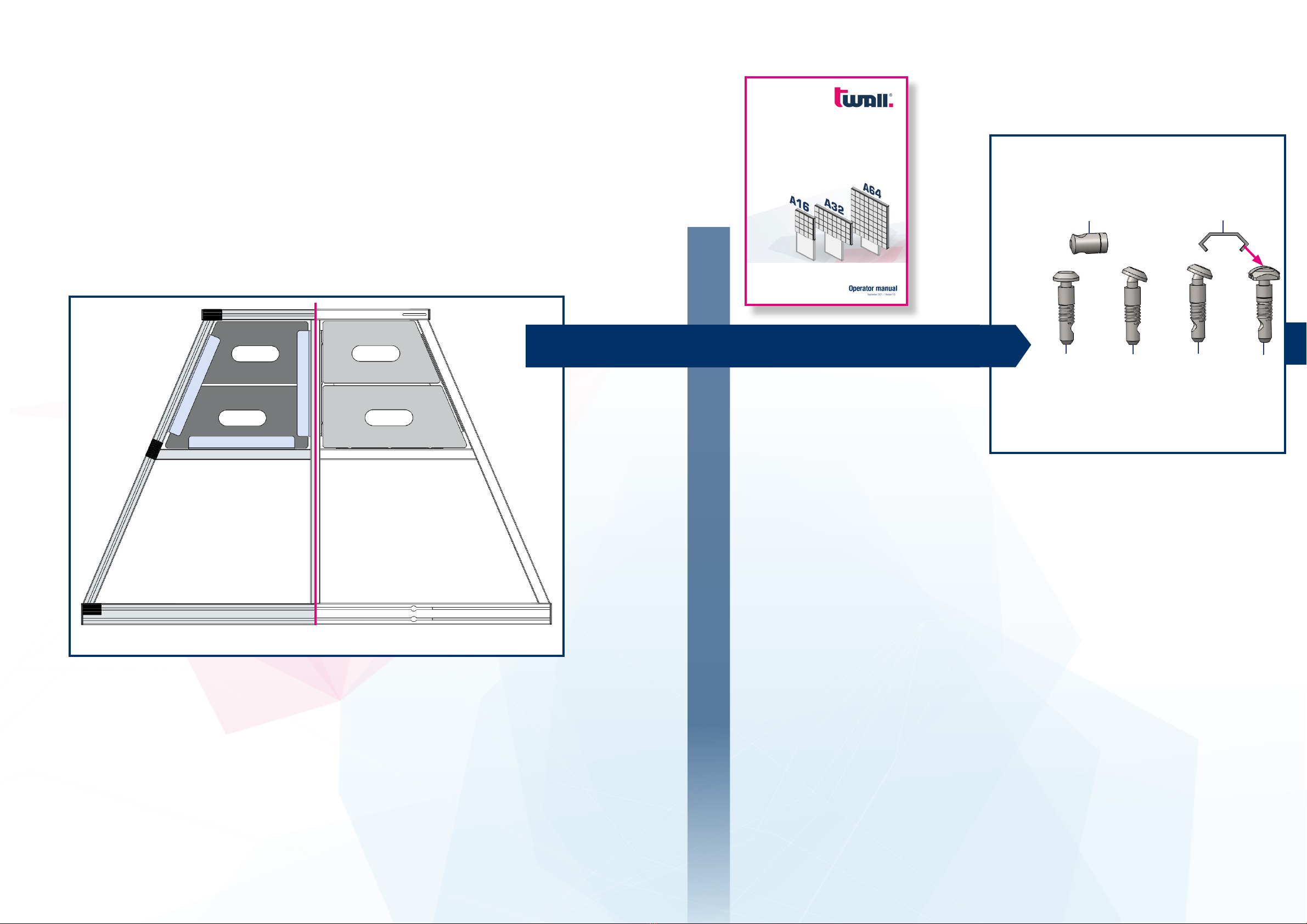
Unpack all the supplied components and check the quantities as fol-
lows:
6x anchors, straight (1)
4x bent anchors, angled -23° (2)
8x bent anchors, angled 23° (3)
2x anchors, square head incl. spring (4)
2x leaf springs for square head (5)
20x cross-pieces with set screw (6)
Fig. 2
Assembly instructions for the universal base frameAssembly instructions for the universal base frame
6
Bottom view Top view

8 9
2x cover caps (black, 80x80) (7)
2x cover caps (black, 40x80) (8)
9x rubber cover proles (black) (9)
18x button head ange screws M8x16 (10)
18x T-nuts M8 with ball (11)
6x support brackets (12)
4x combination proles, 440 mm (13)
1x prole (80x80x1760) (A)
2x proles (40x80x1182) with special angle, left: 23°, right: 23° (B)
1x prole (40x80x1072), straight (C)
1x prole (40x80x586), straight with slot (D)
2x proles (40x80x586) with special angle, left: 23°, right: straight
(E)
7
10 11
Fig. 3 Fig. 4
13 12
Fig. 5 Fig. 6
Arrangement of the individual proles:
Make sure that the smooth surfaces of proles B, C and E face upwards.
Proles A and D have mounting holes that are required for further as-
sembly. These sides must always face upwards (refer to Fig. 5).
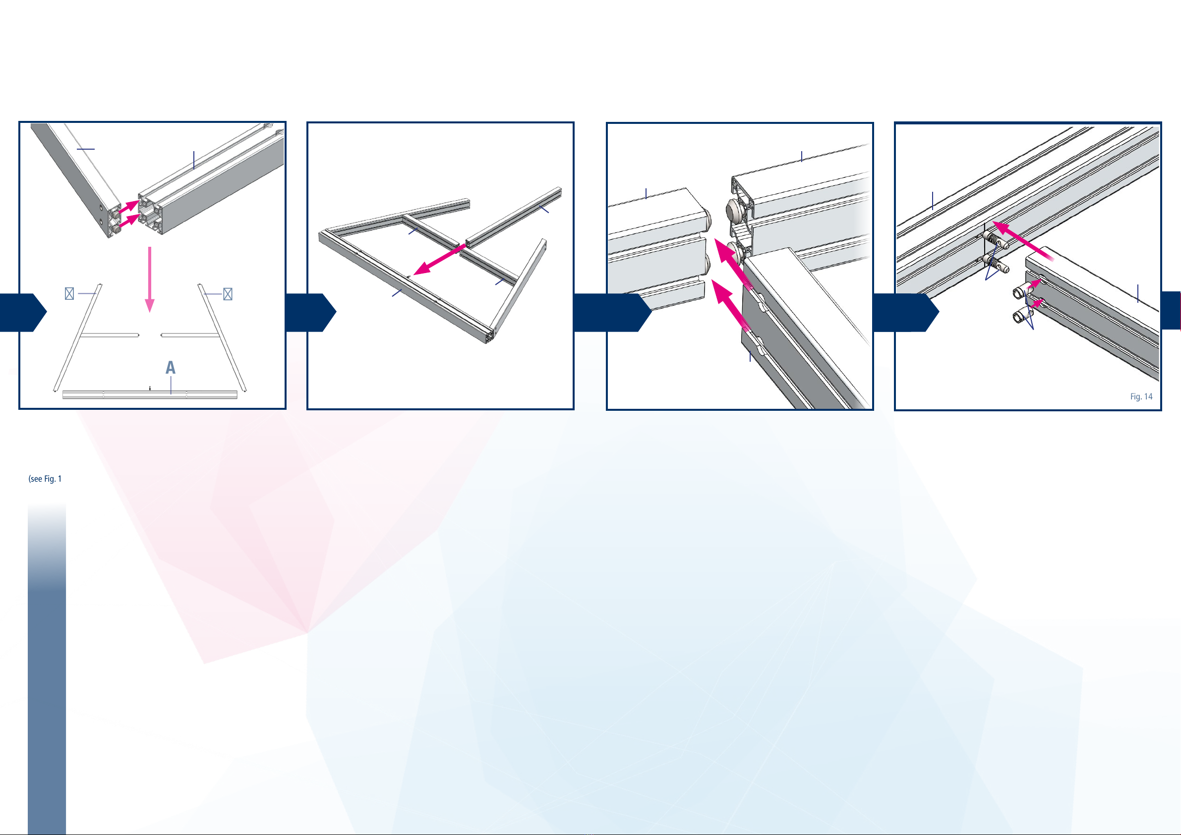
Pre-assembly of the straight anchors
Attach the straight anchors (Fig. 2, item 1) to the straight ends of the
following proles:
• 2x at one end of the prole 40x80x1072 mm (Fig. 4, item C)
• 2x on the proles with angle, left 23° 40x80x586 mm
(Fig. 4, item E)
D
EE
C
BB
A31
6
AB
CD
E
Assembly instructions for the universal base frameAssembly instructions for the universal base frame
89
C/E

10 11
1
6
Fig. 7 Fig. 8 Fig. 9 Fig. 10
6
3
4
A
B
E
4
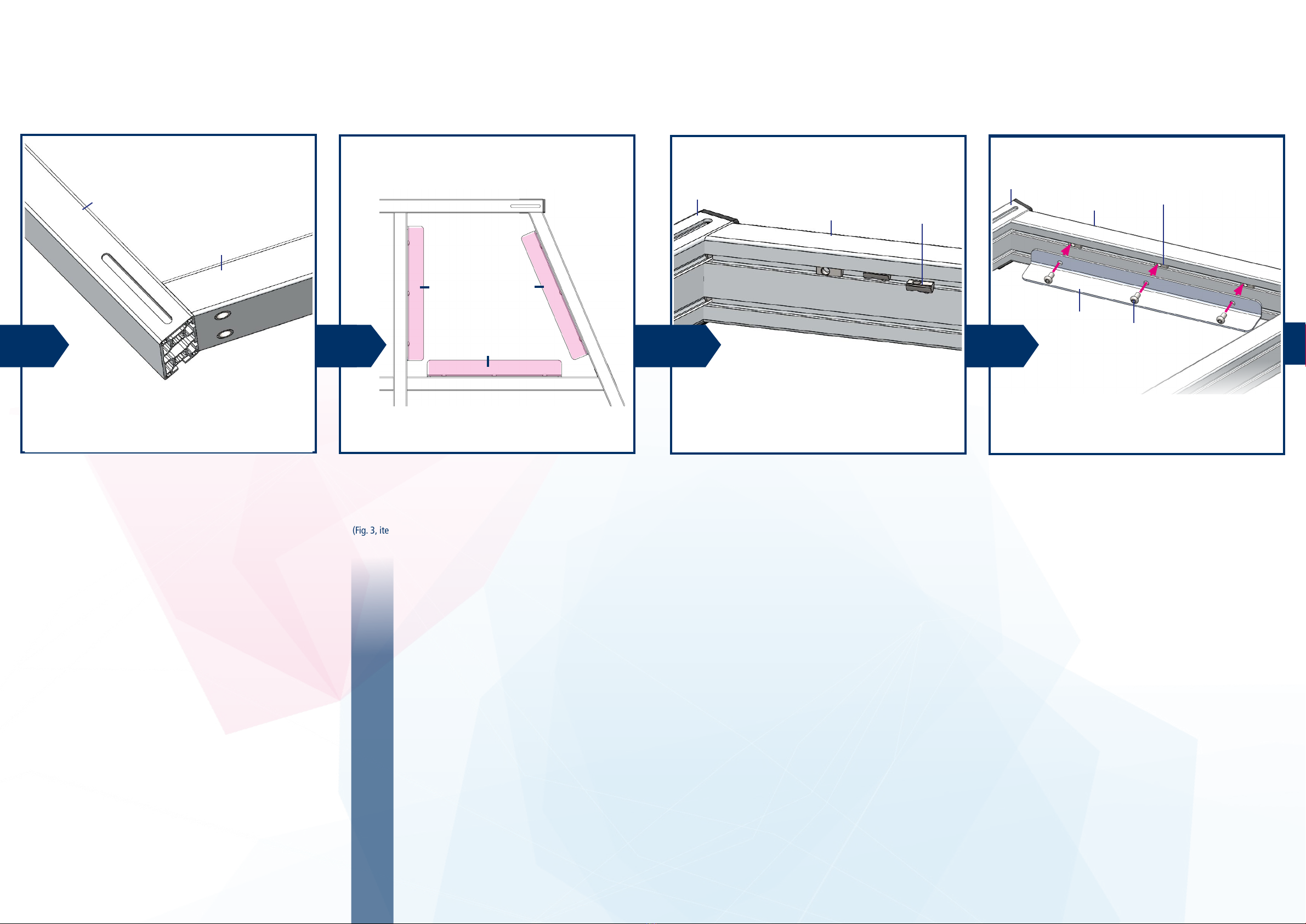
Pre-assembly of the straight anchors
The distance between prole and anchor head should be approx. 5 mm.
Make sure that the anchors are centred, using
the marking for reference.
The square head anchors are inserted in T-shaped grooves on the cor-
responding proles (Fig. 4, item A).
Before assembling the angled side proles (Fig. 4, item B), insert two
square head anchors (Fig. 2, item 4), to which you have attached the leaf
springs (Fig. 2, item 5) in the direction of insertion, into the T-grooves of
the prole Fig. 4, item A) to aid in the later assembly of the
centre prole (Fig. 4, item C).
Make sure that the anchors are centred, using the marking for reference.
Then insert the proles (Fig. 4, item E) into the side proles (Fig. 4,
item B).
Pre-assembly of the bent anchors
Attach the bent anchors, 23°/-23° (Fig. 2) at the angled ends of the
following proles:
• 2x at the ends of the proles with angle, left 23°/right 23°
40x80x1182 mm (Fig. 4, item B)
• 2x at the ends of the proles with angle, left 23° 40x80x586 mm (Fig.
4, item E).
5
Insert the straight anchors and the bent anchors in the centre of the head ends of the
prole pieces.
The tip of the cross-piece set screws is screwed into a recess of the anchor.
The cross-pieces are inserted laterally into the holes on the prole pieces.
Fix the anchors using the cross-piece set screws.
Caution: Do not fully tighten yet!
!
7
Caution: Do not fully tighten the
threaded components yet! Before
the universal base frame can be
assembled, the rubber cover pro-
les must be installed on proles
B and D (Fig. 1 and Fig. 24).
!
Assembly instructions for the universal base frameAssembly instructions for the universal base frame
6
12 13
A
E
Fig. 11 Fig. 12 Fig. 13
E
C
Fig. 14
E
C
BAE
A
C
4
6
10
B
A
B
8 9 7
11
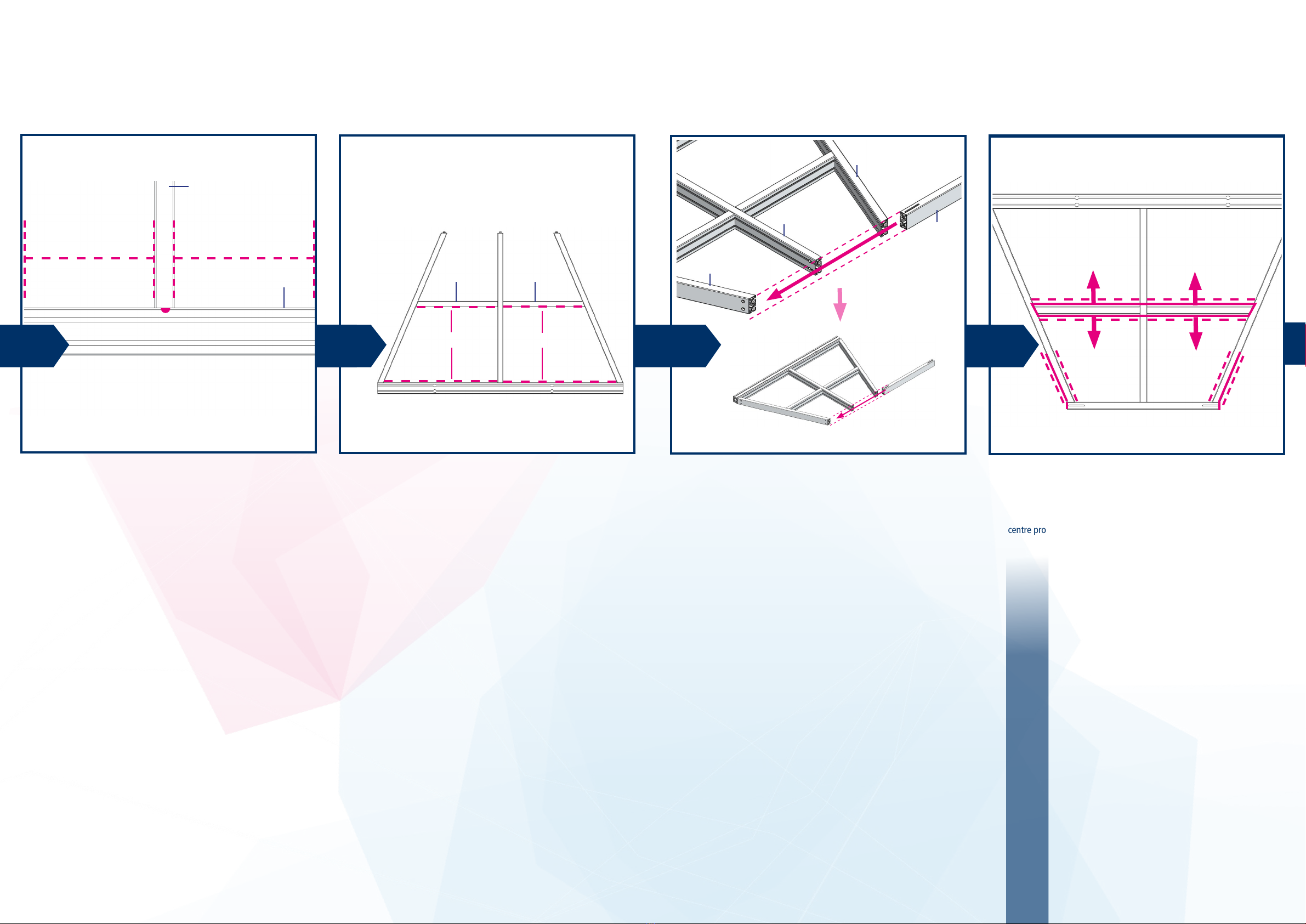
Next, insert the side proles (Fig. 4, item B) into the prole (Fig. 4, item A)
(see Fig. 11).
Insert the pre-assembled anchors of the proles (Fig. 4, item E) into the
grooves of the centre prole (Fig. 4, item C).
Then attach the centre prole (Fig. 4, item C), using the pre-assem-
bled square anchors (Fig. 2, item 4). Before doing so, however, insert
two cross-pieces (Fig. 2, item 6) laterally into the holes of the centre
prole.
Then assemble the centre prole (Fig. 4, item C)
(see Fig. 12).
Caution: Use the same grooves for
this as for the square head anchor
screws!
!
Assembly instructions for the universal base frameAssembly instructions for the universal base frame
14 15
Fig. 15 Fig. 16 Fig. 17
C
A
C
7
When assembling the prole (Fig. 4, item C), make sure that it is cen-
tred properly. Use the marking on the prole (Fig. 4, item A) for this.
Finish the assembly by sliding the prole with slot (Fig. 4,
item D) with its grooves over the pre-assembled anchors of the proles
(Fig. 4, item B/C).
Make sure that the slots are facing upwards.
If the components are not ush, correct the position of the two
centre proles by raising or lowering them.
Align the proles (Fig. 4, item E) so that they are the same
height.
Caution: Make sure that all
components are ush.
!
Fig. 18
12
860 mm 860 mm
13 540 mm 540 mm 14
B
B
D
15
Assembly instructions for the universal base frameAssembly instructions for the universal base frame
EE
16 17
Fig. 20 Fig. 21
7
When all components are correctly aligned, fully tighten all the cross-
piece set screws.
Insert 3 T-nuts (Fig. 3, item 11) into the upper grooves of each of the
proles B, C and D – as shown in Fig. 21.
The following section explains how to assemble the support brackets
(Fig. 3, item 12) for the counterweights.
Caution:When assembling the
support brackets (Fig. 3, item 12)
for the counterweights, make
sure that theT-nuts (Fig. 3, item
11) are inserted into the appro-
priate grooves.
!
Fig. 22
16
D
B
17
12 12
12 18
11
19
11
12 10
Then fasten 3 support brackets (Fig. 3, item 12) to the upper grooves
of each of the proles B, C and D, using the button head ange
screws M8x14 (Fig. 3, item 10).
Fig. 19
Assembly instructions for the universal base frameAssembly instructions for the universal base frame
BB
D
D
18 19
Fig. 24 Fig. 25
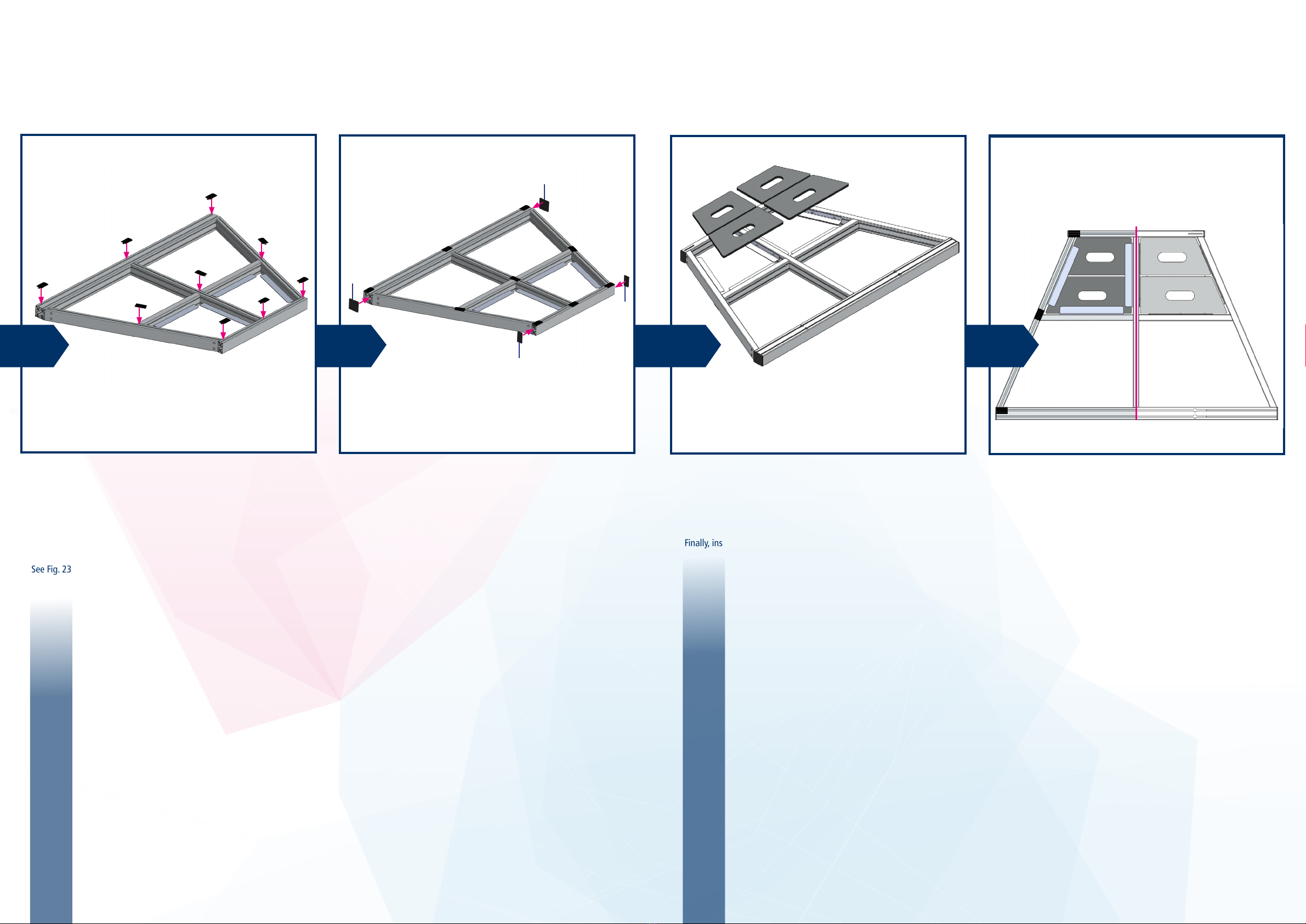
Next, turn the universal base frame on its back to install the rubber
cover proles (Fig. 3, item 9).
This is done by pressing the rubber cover proles into the open grooves
on the bottom.
See Fig. 23 for the correct positioning of the rubber cover proles.
Next, turn the universal base frame over onto the rubber feet.
Finally, insert the counterweights.
Then attach the cover caps (Fig. 3, item 7/8) to the open ends of the
proles.
Caution:The
rubber cover proles are in-
stalled on the bottom.
!
Fig. 26
5
You have completed assembly of the universal base frame of the
twall®.
Fig. 23
Caution: Crush hazard!
!
Congratulations!
Assembly instructions for the universal base frameAssembly instructions for the universal base frame
Bottom view Top view
7
7
8
8
20 21 22
This manual suits for next models
2
Table of contents
Popular Game manuals by other brands


Fundex Games
Fundex Games Timber Tumble User instructions

Go! Gater
Go! Gater 1-1-16453-TP02 Assembly instructions

Smoby
Smoby BBF Challenger quick start guide

Hathaway
Hathaway BG2019SK Assembly instructions

Roberto Sport
Roberto Sport INGLESE Assembly instructions

Beleduc
Beleduc XXL Witches' Kitchen Instruction


