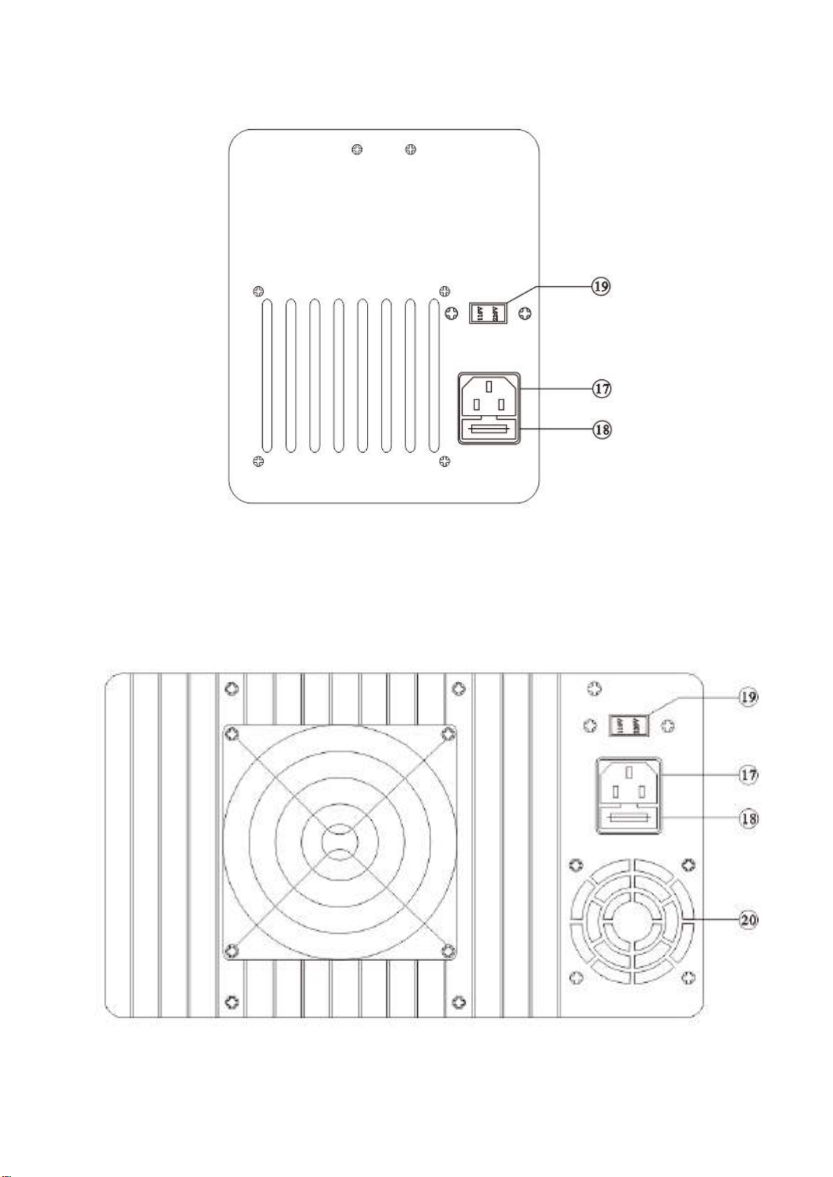
4-3. Rear Panel Control
17 Power socket
18 Fuse holder
19 AC input selector The power transformer is designed to permit operation in 110V (115V/120V)
or 220V (230V/240V),50/60Hz line voltage. To convert from one line voltage
to another is done by change AC input selector as shown in section 6-2.
20 Cooling fan
5. OPERATION INSTRUCTIONS
5-1. Precaution
1) AC input
AC input must be within the range of line voltage ±10% 50/60Hz.
WARNING.
To avoid electrical shock, the power cord protective grounding conductor must be
connected to ground.
2) Installation
Allow enough space around the power supply for ventilation.
WARNING. To avoid damaging the power supply, do not use it in a place where ambient
temperature exceeds 40℃.
WARNING.
Voltages more than 60V DC are a lethal shock hazard to the user. Be careful when
connecting power supplies to achieve voltages higher than 60V DC total or 60V DC between any
connection and earth ground.
CAUTION.
1 The instrument must be operated under rated main supply. If it is meant to work for a long time,
it is suggested to use 60-70% instead of full load so as to avoid rapid aging.
2. Avoid frequent short-circuit operations.
3. In case of the instrument with full load, do not turn on the instrument. Before adding load, adjust
the voltage knob to the minimum value, then turn on the instrument. Next turn the
voltage/current adjustment knob to set targeted values.
5-2. Setting Current Limit
1) Determine the maximum safe current for the device to be powered.
2) Temporarily short the positive “+” negative “-” terminals of the power supply together with a test lead.
3) Rotate the COARSE VOLTAGE control away from zero sufficiently for the CC indicator to light.
4) Adjust the CURRENT control for the targeted current limit. Read the current value on the ammeter.
5) The current limit (over load protection) has now been preset. Do not change the CURRENT control setting
after this step.
6) Remove the short between the “+” and “-” terminals and hook up for constant voltage operation.