twintex TP-2303E User manual

Multi-channel DC Power Supply
TP Series
Operation Manual V1.0
BENCHTOP INSTRUMENT

I
CONTENTS
1. INTRODUCTION.............................................................................................................................- 1 -
2. PRODUCTION MODELS................................................................................................................- 2 -
3. SPECIFICATIONS........................................................................................................................... - 2 -
3-1. Operation Mode .................................................................................................................... - 2 -
3-2. Specifications........................................................................................................................- 3 -
4. PANEL CONTROLS AND INDICATORS.........................................................................................- 4 -
4-1. Panel Illustration....................................................................................................................- 4 -
4-2. Front Panel Control............................................................................................................... - 7 -
4-3. Rear Panel Control................................................................................................................ - 8 -
5. OPERATION INSTRUCTIONS........................................................................................................- 9 -
5-1. Precaution.............................................................................................................................- 9 -
5-2. Setting Current Limit .............................................................................................................- 9 -
5-3. Constant Voltage/Constant Current Characteristic................................................................- 9 -
5-4. Operation Mode .................................................................................................................. - 10 -
5-4-1. Independent Operation.............................................................................................- 10 -
5-4-2. Series Tracking Operation ........................................................................................ - 11 -
5-4-3. Parallel Tracking Operation....................................................................................... - 12 -
5-4-4. Fixed 5V Power Supply Operation............................................................................- 13 -
6. MAINTENANCE ............................................................................................................................- 13 -
6-1. Fuse Replacement..............................................................................................................- 13 -
6-2. Line Voltage Conversion..................................................................................................... - 14 -
6-3. Cleaning..............................................................................................................................- 14 -

- 1 -
1. INTRODUCTION
TP series adjustable DC power supply are designed to be used in applications such as powering operational
amplifier, push pull stages, logic circuit and definition systems where plus and minus voltages are required to
track with an insignificant error, and in any application where three independent power supplies housed in a
single package represent an operating convenience.
The instruments consist of two identical, independently adjustable and one fixed 5V/3A DC power supplies. A
front panel switch selects one of three modes of operation: independent, series and parallel. In the
independent mode, the output voltage and current of each supply are controlled separately, and each supply
is isolated up to 300V from output to chassis or output to output. In the tracking mode, both outputs are
automatically connected in series or parallel, and the controls of the left supply adjust the magnitudes of both
the positive and negative output voltages. Because the outputs are connected in a tracking configuration, any
internal disturbance in the master supply (such as drift or ripple) will cause an equal percentage change in the
outputs of both the supplies.
Each power supply is a completely transistorized, well-regulated, constant voltage/constant current supply
that will furnish full rated output voltage at the maximum output current or can be continuously adjusted
throughout the output range. The front panel current controls can be used to establish the output current limit
(overload or shout circuit) when the supply is used as a constant voltage source (independent or tracking
modes) and the voltage controls can be used to establish the voltage limit (ceiling) when the supply is used as
a constant current source(independent mode only).The supply will automatically cross over from constant
voltage to constant current operation(current limited operation in the tracking mode) and vice versa if the
output current or voltage exceeds these preset limits. Each supply had its own front panel meter that can
measure output voltage and current. One power supply may be used as a master supply controlling, one
slave supplies furnishing various voltages or current for a system. When operated with the front panel mode
switch in the tracking position, the instrument is automatically internally connected in auto-tracking
configuration.
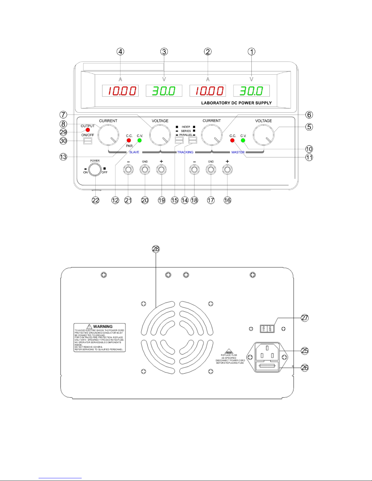
Another feature of this instrument is its output ON/OFF key.
a. For model TP-2303E/2305E/2303K/2305K/2303/2305, it is only the key to cut off or resume the output as
other similar instrument.
b. For model TP-2303TK/2305TK, it is not only the key to cut off or resume the output, but also be endowed
with a new function which its kindred has not. This function is that when the output has been cut off, the both
intending voltage and current can be preset, though in model TP-2303K/2305K/2303/2305 condition, only the
intending voltage can be adjusted. It means that CC preset is very easy as CV preset. Also in this way, an
over current by any unknown load can be avoided. So the new function of the key is a safety design.
Especially this feature is very important to the student use.

- 2 -
2. PRODUCTION MODELS
Item Model Output
Voltage
Output
Current
Output
ON/OFF
Fixed
5V/3A
V/A
preset
Heat Sink Weight
kg
1 TP-2303E 0-30Vx2 0-3A x2 Built-in 7
2 TP-2305E 0-30V x2 0-5A x2 Built-in 9
3 TP-2303K 0-30V x2 0-3A x2 ●●Built-in 7
4 TP-2305K 0-30V x2 0-5A x2 ●●Built-in 9
5 TP-2303 0-30V x2 0-3A x2 ●●External 8
6 TP-2305 0-30V x2 0-5A x2 ●●External 10
7 TP-2303TK 0-30V x2 0-3A x2 ●●●External 8
8 TP-2305TK 0-30V x2 0-5A x2 ●●●External 10
9 TP-30102 0-30V x2 0-10A x2 ●●Built-in 16
10 TP-60052 0-60V x2 0-5A x2 ●●Built-in 16
Dimensions:
TP-30102/TP-60052: 255Wx155Hx460D mm
TP-2303/2305/2303TK/2305TK: 255Wx155Hx370D mm
TP-2303E/2305E/2303K/2305K: 255Wx155Hx330D mm
3. SPECIFICATIONS
3-1. Operation Mode
1) Independent: Two independent outputs and 5V fixed output.
Output from 0 to rating volts and 0 to rating amperes.
2) Series: Output from 0 to ± rating volts at rating amperes each.
Output from 0 to double rating volts at rating amperes.
3) Parallel: Output from 0 to double rating amperes at rating volts.

- 3 -
3-2. Specifications
Constant voltage operation
Line regulation ≤0.01%+3mV
Load regulation ≤0.01%+3mV (I≤3A)
≤0.02%+5mV (I>3A)
Ripple & Noise ≤1mVrms (I≤3A), 5Hz~1MHz
≤2mVrms (I>3A), 5Hz~1MHz
Constant current operation
Line regulation ≤0.2%+3mA
Load regulation ≤0.2%+3mA (I≤3A)
≤0.2%+5mA (I>3A)
Ripple & Noise ≤3mArms (I≤3A)
≤6mArms (I>3A)
Tracking operation
Parallel Line regulation ≤0.01%+3mV
Load regulation ≤0.01%+3mV (I≤3A)
≤0.02%+5mV (I>3A)
Series Line regulation ≤0.01%+5mV
Load regulation ≤300mV
Tracking error ≤0.5%+10mV of the master, no load (with load, add load regulation ≤300mV)
Fixed output
Output voltage 5V±0.25V
Output current 3A
Load regulation ≤25mV @110/220VAC rated input
Ripple & noise
≤2mVrms, 5Hz~1MHz
Display
Voltmeter 3 digits 0.4" LED display
Ammeter 3 digits 0.4" LED display
Resolution
100mV/10mA
Accuracy Real voltage and current output: ±(1% reading+2 digits)
Preset voltage and current: ±(1%reading+8 digits)
General
Insulation Between chassis & terminal: ≥20MΩ/500VDC
Between chassis and AC cord:≥300MΩ/500VDC
Operating environment
0
℃
~40
℃
, ≤80%RH
Storage environment -10℃~70℃, ≤70%RH
Power source AC110V/220V±10%, 50/60Hz
Accessories Power cord x1, Operation manual x1, Test lead x1

- 4 -
4. PANEL CONTROLS AND INDICATORS
4-1. Panel Illustration
a. TP-2303E/2305E Front panel
Fig.4-2
b. TP-2303K/2305K/2303/2305/2303TK/2305TK Front panel
Fig.4-2

- 5 -
c. TP-30102/60052 Front panel
Fig.4-3
d. TP-2303E/2305E/2303K/2305K Rear panel
Fig.4-4

- 6 -
e. TP-2303/2305/2303TK/2305TK Rear panel
Fig.4-5
f. TP-30102/60052 Rear panel
Fig.4-6

- 7 -
4-2. Front Panel Control
22 Power switch : ON/OFF the power input.
1 V LED display : Indicates the MASTER output voltage.
3 V LED display : Indicates the SLAVE output voltage.
2 A LED display : Indicates the MASTER output current.
4 A LED display : Indicates the SLAVE output current.
5 Voltage control : For adjustment of the output voltage of the MASTER supply. Also functions
as adjustment control for the maximum output voltage of the SLAVE supply
when either parallel or series tracking operation.
7 Voltage control : For adjustment of the output voltage of the SLAVE supply when the
independent operation.
6 Current control : For adjustment of the output current of the MASTER supply. Also functions
as adjustment control for the maximum output voltage of the SLAVE supply
when either parallel or series tracking operation.
8 Current control : For adjustment of the output current of the SLAVE supply.
9 Over load indicator : Lights when load on 5 volt supply becomes too large.
10 C.V indicator : Lights when the MASTER supply is in the constant voltage operation, in
either the Series or Parallel Tracking mode, both the MASTER AND SLAVE
supplies are in the constant voltage operation.
12 C.V indicator : Lights when the SLAVE supply is in the constant voltage operation.
11 C. C. indicator : Lights when the MASTER supply is in the constant current operation.
13 C. C. indicator : Lights when the SLAVE supply is in the constant current operation.Also
lights when the TRACKING PARALLEL mode is selected.
14 & 15 TRACKING Mode Switches:
Two push-button switches that select INDEPENDENT mode, SERIES TRACKING
mode, or
PARALLEL TRACKING mode as follows:
a) When both switches are disengaged (out), the unit is in the INDEPENDENT mode and the
MASTER and SLAVE power supplies are completely independent from one another.
b) When the left switch is engaged (in) and the right switch is disengaged (out), the unit is in the
TRACKING SERIES mode.
In this mode, maximum voltage of both supplies is set usi
ng the MASTER VOLTAGE controls
(voltage at output terminals of the SLAVE supply tracks the voltage at the output terminals of
the MASTER supply). Also, in this mode of operation the positive terminal (red) of the SLAVE
supply is connected to the negative terminal (black) of the MASTER supply.
This allows the two supplies to be used as one 0 to double rating voltage supply.
c)
When both switches are engaged (in), the unit is in the TRACKING PARALLEL mode. In this
mode the MASTER and
SLAVE supplies are wired together in parallel and both the maximum current and voltage are
set using the MASTER controls. The MASTER and SLAVE outputs can be used as two
individual (but tracking) power supplies or just the MASTER output can be used as a 0 to rating
voltage supply with a 0 to double rating current capability.

- 8 -
16 “+” Output terminal : Positive polarity output terminal for the MASTER supply.
19 “+” Output terminal : Positive polarity output terminal for the SLAVE supply.
17 “GND” terminal : Earth and chassis ground.
20 “GND” terminal : Earth and chassis ground.
18 “-” Output terminal : Negative polarity output terminal for the MASTER supply.
21 “-” Output terminal : Negative polarity output terminal for the SLAVE supply.
23 “+” Output terminal : Positive polarity output terminal for 5V supply.
24 “-” Output terminal : Negative polarity output terminal for 5V supply.
29 Output indicator : Lights when switch is engaged (in).
30 Output ON/OFF
switch : DC power supply output when switch is engaged (in).And when output is
off, both the voltage and current can be adjusted before the output is
resumed.
4-3. Rear Panel Control
25 Power socket
26 Fuse holder
27 AC input selector The power transformer is designed to permit operation in 110V (115V/120V)
or 220V (230V/240V), 50/60Hz line voltage. To convert from one line voltage
to another is done by change AC input selector as shown in section 6-2.
28 Cooling fan

- 9 -
5. OPERATION INSTRUCTIONS
5-1. Precaution
1) AC input
AC input must be within the range of line voltage ±10%, 50/60Hz.
WARNING.
To avoid electrical shock, the power cord protective grounding conductor must be
connected to ground.
2) Installation
Avoid using the supply in a place where the ambient temperature exceeds 40℃.
Allow enough space around the power supply for ventilation.
WARNING.
To avoid damaging the power supply, do not use it in a place where ambient
temperature exceeds 40℃.
WARNING.
Voltages more than 60V DC are a lethal shock hazard to the user. Be careful when
connecting power supplies to achieve voltages higher than 60V DC total or 60V DC between any
connection and earth ground.
Operation mode: single or tracking (serial or parallel) operation (two units).
CAUTION.
1 The instrument must be operated under rated main supply. If it is meant to work for a long time,
it is suggested to use 60-70% instead of full load so as to avoid rapid aging.
2. Avoid frequent short-circuit operations.
3. In case of the instrument with full load, do not turn on the instrument. Before adding load, adjust
the voltage knob to the minimum value, then turn on the ins
trument. Next turn the
voltage/current adjustment knob to set targeted values.
3) Output voltage overshoot
Voltage between output terminals may exceed the present value when the power is turned on or off.
5-2. Setting Current Limit
1) Determine the maximum safe current for the device to be powered.
2) Temporarily short the positive “+” negative “-” terminals of the power supply together with a test lead. But for
TP-2303TK/2305TK/30102/60052, just pushing the output ON/OFF key can make the short circuit function.
3) Rotate the COARSE VOLTAGE control away from zero sufficiently for the CC indicator to light.
4) Adjust the CURRENT control for the targeted current limit. Read the current value on the ammeter.
5) The current limit (over load protection) has now been preset. Do not change the CURRENT control setting
after this step.
6) Remove the short between the “+” and “-” terminals and hook up for constant voltage operation.
5-3. Constant Voltage/Constant Current Characteristic
The working characteristic of this series Power Supplies is called a constant voltage/constant current
automatic crossover type. This permits continuous transition from constant current to constant voltage modes
in response to the load change. The intersection of constant voltage and constant current modes is called the
crossover point. Fig.5-1 shows the relationship between this crossover point and the load.

- 10 -
For example, if the load is such that the power supply is operating in the constant voltage mode, a regulated
output voltage is provided. The output voltage remains constant as the load increases up until the point where
the preset current limit is reached. At that point, the output current becomes constant and the output voltage
drops in proportion to further increases in load. The point is indicated by the front panel LED indicators. The
crossover point is reached when the CV indicator goes off and the CC indicator comes on.
Similarly, good example of this would be seen when charging a 12-volt battery. Initially, the open circuit
voltage of the power supply may be preset for 13.8 volts. A low battery will place a heavy load on the supply
and it will operate in the constant current mode, which may be adjusted for a 1 amp charging rate. As the
battery becomes charged, and its voltage approaches 13.8 volts, its load decreases to the point where it no
longer demands the full 1 amp charging rate. This is the crossover point where the power supply goes into the
constant voltage mode.
Crossover from the constant current to the constant voltage mode automatically occurs from a decrease in
load.
Fig.5-1 Constant Voltage/Constant Characteristic
5-4. Operation Mode
5-4-1. Independent Operation
The "MASTER" and "SLAVE" supplies each provide a 0 to rating volts output at up to rating amps. This
procedure covers the use of the MASTER and SLAVE supplies only when they are used independently from
one another. When used in the INDEPENDENT operating mode, the operating controls of the two power
supplies are completely independent and either supply can be used individually or both can be used
simultaneously.
A. Disengage both TRACKING mode switches (both switches out) so that the power supply is in the
INDEPENDENT operating mode.
B. Adjust "Voltage" control and "Current" control to the desired output voltage and current.

- 11 -
C. Turn off the power supply and the equipment to be powered during hook-up.
D. Connect the positive polarity of the device being powered to the red (+) terminal of the power supply.
E. Connect the negative polarity of the device being powered to the black (-) terminal of the power supply.
F. Fig.5-2 illustrates the connection procedure.
Fig.5-2 Independent Operation
5-4-2. Series Tracking Operation
When the series tracking mode of operation is selected, the positive (red) terminal of the SLAVE supply output
is internally connected to the negative (black) terminal of the MASTER supply.
In the series tracking mode, the maximum output voltage of both MASTER and SLAVE supplies can be
simultaneously varied with one control. The maximum SLAVE supply voltage is automatically set to the same
value as the MASTER supply by using the MASTER VOLTAGE controls.
A. Set the power supplies to the TRACKING SERIES mode by engaging the left TRACKING switch and
release the right TRACKING switch. In this case, the output voltage (across the two supplies) is actually
double the displayed value.
For example, if the MASTER display is set for voltage metering and the SLAVE display for current metering,
the output voltage across the MASTER positive (red) terminal and the SLAVE negative (black) terminal
would be double the reading on the MASTER LED Display (since both supplies are putting out the same
voltage). The actual output current would be the value read from the SLAVE LED Display (since the two
supplies are wired in series, current flowing through each supply must be equal).
B. Set the SLAVE CURRENT control the fully clockwise position. The maximum current is set using the
MASTER CURRENT control. Follow the instructions for "Setting Current Limit" (INDEPENDENT USE OF
"MASTER" OR "SLAVE" SUPPLY section of this manual, using the MASTER CURRENT control.
NOTE:
Because the supplies are being used in series, either CURRENT control can be used to set maximum
current. If desired, the MASTER CURRENT control can be rotated fully clockwise and the SLAVE
CURRENT control can be used to adjust the maximum current value. Because current through the two
supplies must be equal when they are being used in series, the lower CURRENT control setting will set
the maximum output current.
C. Adjust the output voltage to the desired level using the MASTER VOLTAGE controls.
D. Turn off the power supply and the equipment to be powered during hook-up.

- 12 -
E. If "single supply" operation is desired, this allows the power supply to be used as twice the voltage and
rating current simply by using the negative (black) terminal of the SLAVE supply and the positive (red)
terminal of the MASTER supply, the configuration as shown in Fig.5-3.
Fig.5-3 Single Supply
If the chassis or common of the equipment being powered is separate from both positive and negative
polarity power inputs. The output of the SLAVE (negative) supply is tracking the output of the MASTER
(positive) supply. The configuration is shown in Fig.5-4.
Fig.5-4 Positive and Negative Supply
5-4-3. Parallel Tracking Operation
In the parallel tracking mode of operation, both supplies are strapped together (in parallel). This allows for a
rating voltage supply with a double rating current capability. Only the MASTER output terminals are used for
parallel tracking operation. In the parallel tracking mode, the SLAVE supply output voltage and current are
tracking the MASTER supply output voltage and current.
A. Set the power supplies to the TRACKING PARALLEL mode by engaging both TRACKING switches.
B. Because both voltage and current of the SLAVE supply track the MASTER supply, the maximum current
and voltage are set using the MASTER controls. Using the MASTER supply output jacks, follow the
instructions for "Setting Current Limit" (5-2 Section). Remember that the actual current output at the
MATER supply output jack is double the reading on the SLAVE indicator meter.. Then push the output
on/off key to enter voltage and current setting.
C. Adjust the output voltage to the desired level using the MASTER VOLTAGE controls.
D. Turn off the power supply and the equipment to be powered during hook-up.
E. Connect the positive polarity of the device being powered to the red (+) terminal of the MASTER power
supply.

- 13 -
F. Connect the negative polarity of the device being powered to the black (-) terminal of the MASTER power
supply. The configuration is as shown in Fig.5-5.
Fig.5-5 Parallel Tracking Operation
5-4-4. Fixed 5V Power Supply Operation
The fixed 5V supply provides a 5V DC output with a 3 amp current capacity. The supply is ideal for use with
TTL circuits.
A. Turn off the power supply and the equipment to be powered during hook-up.
B. Connect the polarity the device being powered to the red (+) terminal of the 5V supply.
C. Connect the negative polarity of the device being powered to the black (-) terminal of the 5V supply.
D. If the red OVERLOAD indicator lights, too much load has been placed on the supply. This will cause
voltage and current to drop and prevent proper operation of the 5V supply. To correct this situation, the
load on the supply must be decreased so that no more than 3 amps of current are sucked.
6. MAINTENANCE
WARNING
The following instructions are for use by qualified personnel only. To avoid electrical shock, do not perform
any servicing other than contained in the operating instruction unless you are qualified to do so.
6-1. Fuse Replacement
If the fuse blows, the CV or CC indicators will not light and the power supply will not operate. The fuse shall
not normally open unless a problem has developed in the unit. Try to determine and correct the cause of the
blown fuse, then replace only with a fuse of the correct rating type.
The fuse is located in rear panel.
WARNING. For continued fire protection, replace fuse only with 250V of the specified type and
rating. And disconnect the power cord before replacing fuse.
WARNING. To protect the transformer and circuits of the unit, a fuse of the correct rating and type
must be used. Refer to below for correct fuse ratings.

- 14 -
Fuse rating:
Model 220VAC rated input 110VAC rated input
TP-2303E TSD3.15A TSD6.3A
TP-2303K TSD3.15A TSD6.3A
TP-2303 TSD3.15A TSD6.3A
TP-2303TK TSD3.15A TSD6.3A
TP-2305E TSD6.3A TSD10A
TP-2305K TSD6.3A TSD10A
TP-2305 TSD6.3A TSD10A
TP-2305TK TSD6.3A TSD10A
TP-30102 TSD10A TSD10A
TP-60052 TSD10A TSD10A
6-2. Line Voltage Conversion
The primary winding of the power transformer is tapped to permit operation from 110 or 220Vac ±10%,
50/60Hz line voltage. Conversion from one line voltage to another is done by change AC input selector switch.
The rear panel identifies the line voltage to which the unit was factory set. To convert to a different line voltage,
perform the following procedure:
1) Make sure the power cord is unplugged.
2) Change the AC select switch to the desired line voltage position.
3) A change in line voltage may also require a corresponding change of fuse value. Install the correct
fuse as listed on rear panel.
lf the output voltage is unstableness, please check the AC line that it may be less than 207V/105V.
6-3. Cleaning
To clean the power supply, use a soft cloth dampened in a solution of mild detergent and water. Do not spray
cleaner directly onto the instrument, since it may leak into the cabinet and cause damage.
Do not use chemicals containing benzene, benzene, toluene, xylene, acetone, or similar solvents.
Do not use abrasive cleaners on any portion of the power supply.
Should the problems can not be solved, please contact local distributor or the manufacturer.
This manual suits for next models
9
Table of contents
Other twintex Power Supply manuals