CREATIVE ELECTRONICS SMC-3303X User manual

No.35, Hartron Complex, Sector-18, Electronic City, Type-A, Udyog Vihar, Phase-IV, Gurugram 122015 Haryana, India
Tel: +91-124-4909 850; Fax: +91-11 66173638
Email: ptgsales@smcel.com; Web: www.smcel.com
Triple Output Digital
Power Supply
Model No.: SMC-3303X
Operation Manual
BENCHTOP INSTRUMENT
S.M.CREATIVE
ELECTRONICS LIMITED

No.35, Hartron Complex, Sector-18, Electronic City, Type-A, Udyog Vihar, Phase-IV, Gurugram 122015 Haryana, India
Tel: +91-124-4909 850; Fax: +91-11 66173638
Email: ptgsales@smcel.com; Web: www.smcel.com
SAFEFY INSTRUCTION........................................................................................................................................I
1. OVERVIEW.....................................................................................................................................................- 1 -
1.1 Operation and Storage Environment...................................................................................................- 1 -
1.2 Introduction ...........................................................................................................................................- 1 -
1.5 Front Panel Overview............................................................................................................................- 2 -
1.6 Rear Panel Overview.............................................................................................................................- 5 -
1.7 CV/CC Crossover Characteristics .......................................................................................................- 6 -
2. SETUP ..............................................................................................................................................................- 7 -
2.1 Power Up................................................................................................................................................- 7 -
2.2 Load Cable Connection.........................................................................................................................- 7 -
2.3 Output ON/OFF.....................................................................................................................................- 8 -
2.4 Beep ON/OFF.........................................................................................................................................- 8 -
2.5 Front Panel Lock ...................................................................................................................................- 8 -
3. OPERATION...................................................................................................................................................- 9 -
3.1 CH1/CH2 Independent Mode...............................................................................................................- 9 -
3.2 CH3 Independent Mode........................................................................................................................- 9 -
3.3 CH1/CH2 Tracking Series Mode........................................................................................................- 10 -
3.4 CH1/CH2 Tracking Parallel Mode ....................................................................................................- 13 -
4. SAVE/RECALL SETUP...............................................................................................................................- 15 -
4.1 Save Setup ............................................................................................................................................- 15 -
4.2 Recall Setup..........................................................................................................................................- 15 -
5. REMOTE CONTROL ..................................................................................................................................- 16 -
5.1 Remote Control Setup.........................................................................................................................- 16 -
5.2 Remote Connection Step.....................................................................................................................- 16 -
5.3 Command Syntax.................................................................................................................................- 17 -
5.4 Error Messages....................................................................................................................................- 17 -
5.5 Command List......................................................................................................................................- 17 -
5.6 Command Details.................................................................................................................................- 18 -
6. MAINTENANCE...........................................................................................................................................- 21 -
6.1 Inspection .............................................................................................................................................- 21 -
6.2 Fuse Replacement................................................................................................................................- 21 -
6.3 Cleaning................................................................................................................................................- 21 -
I
SAFEFY INSTRUCTION
This chapter contains important safety instructions that you must follow when operating the instrument and when
keeping it in storage. Read the following before any operation to insure your safety and to keep the best condition for
the instrument.
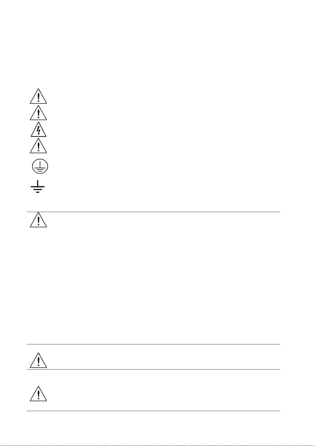
Safety Symbols
The following safety symbols may appear in this manual or on the instrument:
WARNING Identifies conditions or practices that could result in injury or loss of life.
CAUTION Identifies conditions or practices that could result in damage to the instrument or to
other properties.
DANGER High voltage
ATTENTION Refer to the manual
Protective conductor terminal
Earth (ground) terminal
Safety Guidelines
CAUTION
Before plugging into local AC mains, check and make sure that the output voltage is
compatible to the load. (It is suggested to disconnect a load before plugging into
local AC mains.
Do not use this instrument near water.
Do not operate or touch this instrument with wet hands.
Do not open the casing of the instrument when it is connected to AC mains.
The max.output voltage of the instrument may be over 60VDC, avoid touch the
metal contact part of the output terminals.
Do not use the instrument in an atmosphere which contains sulfuric acid mist or
other substances which cause corrosion to metal.
Do not use the instrument in a dusty place or a highly humid place as such will
cause instrument reliability degradation and instrument failures.
Install the instrument in a place where is free from vibration.
Install the instrument in a place where the ambient temperature is in range of
-10~70℃.Note that the instrument operation may become unstable if it is operated
in an ambient temperature exceeding the range of 0~40℃
Power supply
WARNING
AC Input voltage: 110V/220V ±10%, 50/60Hz
Connect the protective grounding conductor of the AC power cord to an earth ground to
avoid electrical shock.
Fuse
WARNING
Fuse type: 110V: T6.3A /250V, 220V: T3.15A/250V.
Make sure the correct type of fuse is installed before power up.
Replace the AC fuse with the same type and rating as the original fuse.
Disconnect the power cord before fuse replacement.
Make sure the cause of fuse blowout is fixed before fuse replacement.

- 1 -
1. OVERVIEW
This chapter describes the instrument in a nutshell, including its main features and front /rear panel introduction. After
going through the overview, follow the SETUP chapter to properly power up and set operation environment.
1.1 Operation and Storage Environment
Operation Environment
Location: Indoor, no direct sunlight, dust free, almost non-conductive pollution (note below)
Relative Humidity: < 80%
Altitude: < 2000m
Temperature: 0° to 40°
Storage Environment
Location: Indoor
Relative Humidity: < 70%
Temperature: -10° to 70°
1.2 Introduction
This series of regulated programmable DC power supply are light weight, adjustable, multifunctional work stations.
They have three independent outputs: two with adjustable voltage level and one with fixed level selectable from 2.5V,
3.3V and 5V. The power supply can be used for logic circuits where various output voltage or current are needed, and
for tracking mode definition systems where positive and negative voltages with good accuracy are required.
Independent /Tracking Series /Tracking Parallel
The three output modes of the power supply - independent, tracking series, and tracking parallel - can be selected by
pressing the TRACKING key on the front panel. In the independent mode, the output voltage and current of each
channel are controlled separately. The isolation degree, from output terminal to chassis or from output terminal to
output terminal, is 300V. In the tracking modes, both the CH1 and CH2 outputs are automatically connected in series or
parallel; no need to connect output leads. In the series mode, the output voltage is doubled; in the parallel mode, the
output current is doubled.
Constant Voltage/Constant Current
Except for CH3, each output channel is completely transistorized and well-regulated, and works in constant voltage
(CV) or constant current (CC) mode. Even at the maximum output current, a fully rated, continuously adjustable output
voltage is provided. For a big load, the power supply can be used as a CV source; while for a small load, a CC source.
When in the CV mode (independent or tracking mode), output current (overload or short circuit) can be controlled via
the front panel. When in the CC mode (independent mode only), the maximum (ceiling) output voltage can be
controlled via the front panel. The power supply will automatically cross over from CV to CC operation when the
output current reaches the target value. The power supply will automatically cross over from CC to CV when the output
voltage reaches the target value. For more details about CV/CC mode operation, see page8.
Automatic Tracking Mode
The front panel display (CH1, CH2) shows the output voltage or current. When operating in the tracking mode, the
power supply will automatically connect to the auto- tracking mode.

- 2 -
Main Features
Performance Low ripple & noise, intelligent cooling fan
Compact design, light weight
Operation
Constant voltage/constant current operation
Tracking series/tracking parallel operation
Output ON/OFF control
3 outputs:30V/3A×2, 2.5V/3.3V/5V/3A×1
Digital panel control
Panel lock function
4 programming presets for voltage and current save/recall
Coarse and fine control for voltage and current
Software calibration
Beeper output
Voltage and current limit preset
Protection Over load, over temperature protections
Reverse polarity protection
Interface
USB interface for remote PC control
1.5 Front Panel Overview
Fig.1.5-1 Front panel
- 3 -
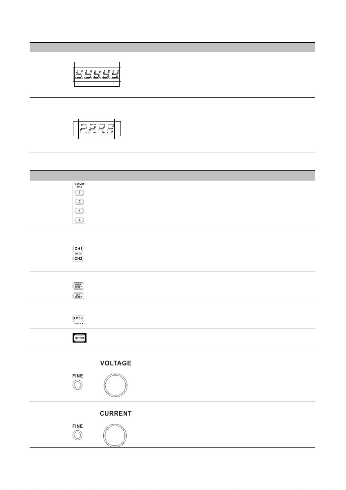
Display
Voltmeter
Displays CH1 or CH2 output voltage
`
V
Ammeter Display CH1 or CH2 output current
A
Control Panel
Memory keys
Saves or recalls panel settings. Max.4 sets for programming preset. Refer
to page 17 for details.
CH1/CH2
beep keys
Selects the output channel for level adjustment. Refer to page 11 for
level setting details
Pressing and holding CH2 key enables beep sound. Refer to page 10 for
details.
Parallel/Series
keys
Activates Tracking Parallel operation or Tracking Series operation. Refer
to page 12 for details.
Lock key Locks or unlocks the front panel settings. Refer to page 10 for details.
Output key Turns the output on or off.
Voltage
knobs
Adjusts the output voltage level for CH1 or CH2. Pressing the knob
switches for coarse and fine level setting. When in fine adjustment, the
FINE indicator lights on.
Current knobs
Adjusts the output current level for CH1 or CH2. Pressing the knob
switches coarse and fine level setting. When in fine adjustment, the
FINE indicator lights on.

- 4 -
Terminals
Power switch
Turns on or off the main power. Refer to page 9 for power up
sequence.
GND terminal Accepts a grounding wire.
CH1 output Outputs CH1 voltage and current.
CH1 CV/CC
indicator
Indicates CH1 constant voltage or constant current operation mode.
CH2 output Outputs CH2 voltage and current.
CH2 CV/CC/
PAR indicator
Indicates CH2 constant voltage, constant current or tracking parallel
operation mode.
CH3 output
Outputs CH3 voltage and current.
CH3 overload
Indicator Indicates when CH3 output current is overloaded.
CH3 voltage
Selector Selects CH3 output voltage from 2.5V, 3.3V, 5V.

- 5 -
1.6 Rear Panel Overview
Fig.1.6-1 Rear panel of models with USB interface
USB connector
Accepts a USB slave connector for command-based remote control (page 18).
For models with USB interface.
Power cord/fuse
socket
The power cord socket accepts the AC mains. Refer to page 9 for power up
details.
The fuse holder contains the AC main fuse. Refer to page 23 for details of
fuse replacement.
AC line voltage
selector Selects AC line voltage from 110V/220V.
- 6 -
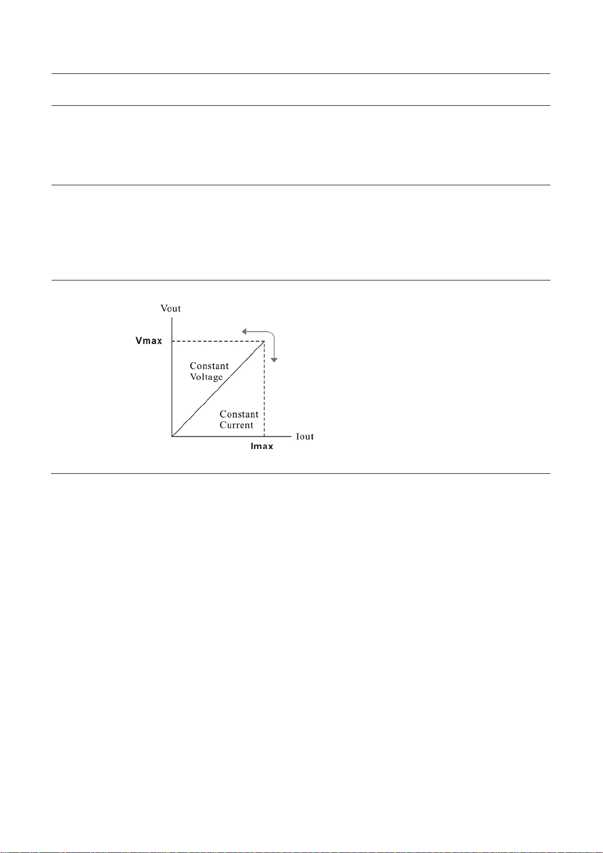
1.7 CV/CC Crossover Characteristics
Background The instrument automatically switches between constant voltage mode (CV) and constant current
mode (CC), according to load condition.
CV mode When the current level is smaller than the output setting, the instrument operates in Constant
Voltage mode. The indicator on the front panel turns green (C.V.) The Voltage level is kept at the
setting and the Current level fluctuates according to the load condition until it reaches the output
current setting.
CC mode When the current level reaches the output setting, the instrument starts operating in Constant Current
mode. The indicator on the front panel turns red (C.C.) The Current level is kept at the setting but
the Voltage level becomes lower than the setting, in order to suppress the output power level from
overload. When the current level becomes lower than the setting, the instrument goes back to the
Constant Voltage mode.
Diagram
- 7 -
2. SETUP
This chapter describes how to properly power up and configure the power supply series before operation.
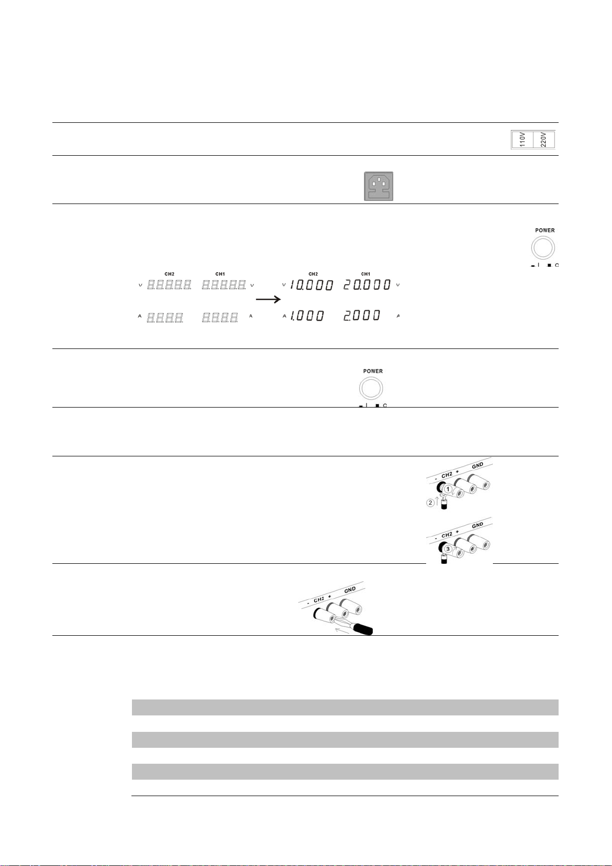
2.1 Power Up
Select AC line
voltage
Before powering up the power supply, select the AC input voltage from the rear panel.
Connect AC
power cord
Connect the AC power cord to the rear panel socket.
Power on Press the power switch to turn on the power. The display shows the initialization screen,
followed by the last recalled settings.
Power off Press the power switch again to turn off the power.
2.2 Load Cable Connection
Standard
accessory
1. Turn the terminal counterclockwise and loosen the screw.
2. Insert the cable terminal.
3. Turn the terminal clockwise and tighten the screw.
Banana plug Insert the plug into the socket.
Wire type When using load cables other than the attached, make sure they have enough current capacity for
minimizing cable loss and load line impedance. Voltage drop across a wire should not excess 0.5V.
The following list is the wire current rating at 450A/cm
2
.
Wire size (AWG)
Max. current (A)
20
2.5
18
4
16
6
14
10
12 16
- 8 -
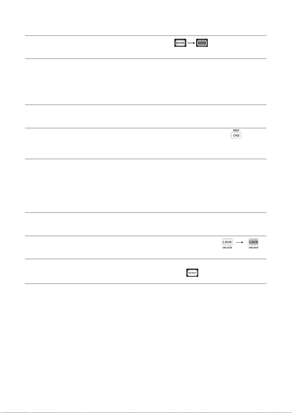
2.3 Output ON/OFF
Panel operation Pressing the Output key turns on all CH 1/2/3 outputs.
The key LED also turns on. Pressing the Output key again turns off the output and the key LED.
Automatic
output off
Any of the following actions during output on automatically turns it off. They might involve sudden
and harmful change in the output level.
Change the operation mode between independent / tracking series / tracking parallel
Recalling other setups from the memory
Storing the setup into the memory
2.4 Beep ON/OFF
Panel operation By default, the beeper sound is enabled. To turn off the beep, press the beep key
for 2 seconds.
A beep sound comes out and the beeper setting will be turned off. To enable the beeper, press the
beep key again for 2 seconds.
List of beeper
The following operations go with a beep sound when the beeper setting is on.
Power on
INDEP – SER – PAR mode switching
Setup save/recall
Voltage/current knob, fine/coarse knob
Output on/off
Panel lock/unlock
CH1/CH2 output level knob
Voltage/current level reaching minimum
(zero) level
2.5 Front Panel Lock
Panel operation Press the LOCK key to lock the front panel key operation. The key LED
turns on. To unlock, press the LOCK key for 2 seconds. The key LED also
turns off.
Note The OUTPUT key is not affected by the lock operation.
- 9 -
3. OPERATION
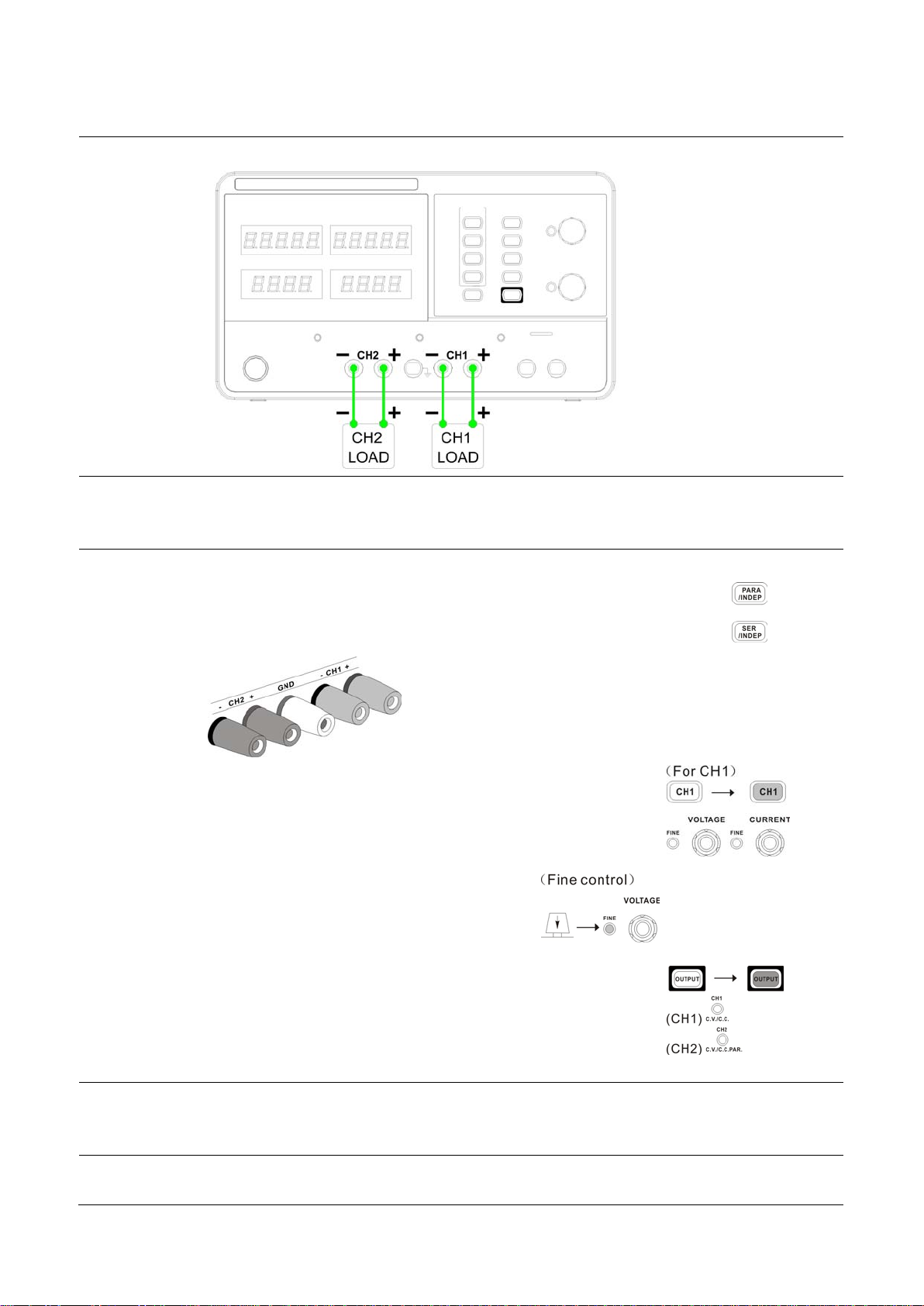
3.1 CH1/CH2 Independent Mode
Background/
Connection
CH1 and CH2 outputs work independent of each other and are separately controlled.
Output rating 0~30V/0~3A for each channel (I≤3A)
0~30V/0~5A for each channel (I>3A)
Panel operation 1. Make sure the PARA INDEP and SERIES INDEP keys are turned off (the
key LEDs are off)
2. Connect the load to the front panel terminals, CH1 +/-, CH2 +/-.
3. Set the CH1 output voltage and current. Press the CH1 switch
(LED turns on) and use the Voltage and Current knob. By default,
the Voltage and Current knob work in the coarse mode. To
activate the fine mode, press the knob and turn on the FINE LED.
Coarse: 0.1V or 0.1A @ rotation click.
Fine: the smallest digit @ rotation click.
4. Repeat the above settings for CH2 channel.
5. To turn on the output, press the output key. The key LED turns on
and the CH1 /CH2 indicator shows the output mode, CV or CC.
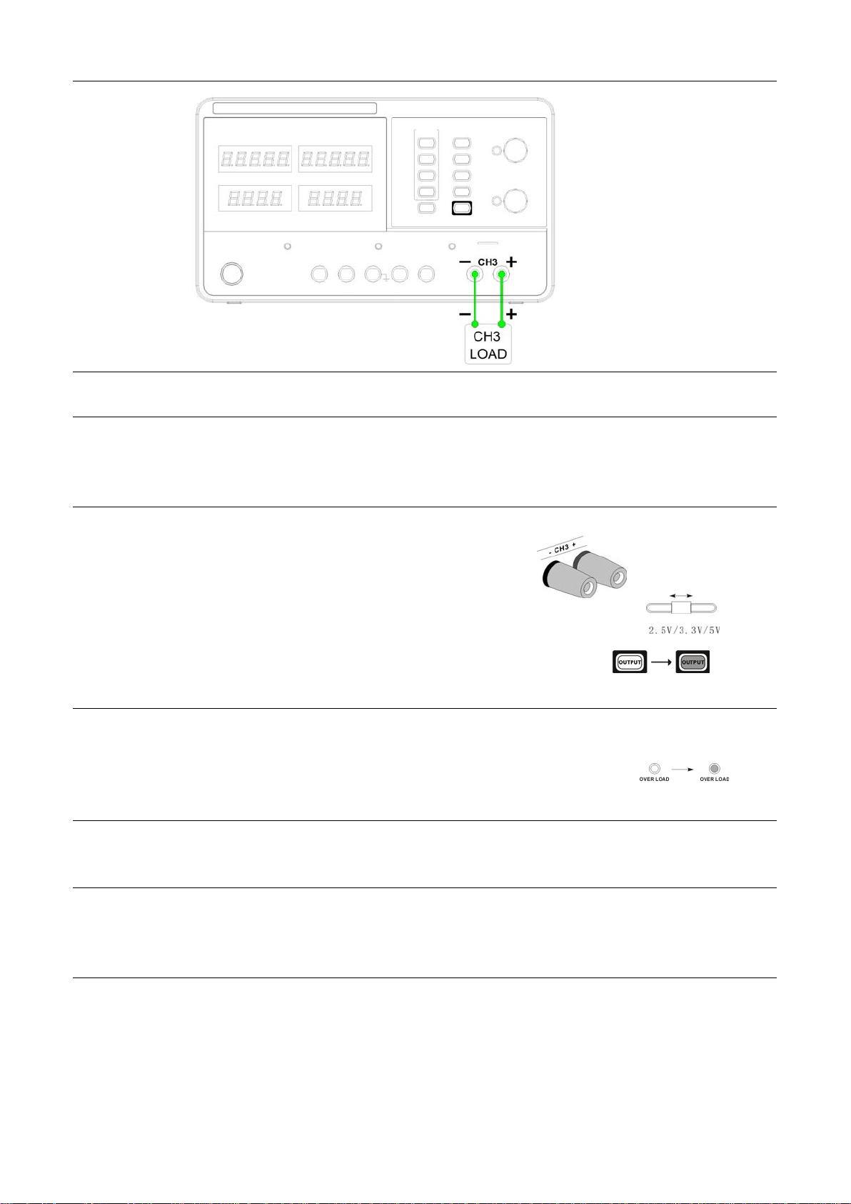
3.2 CH3 Independent Mode
Background/
Connection
The CH3 rating is 2.5V/3.3V/5V, maximum 3A. It works independently from CH1 and CH2,
regardless of their modes.
- 10 -
Output rating
Fixed 2.5V/3.3V/5V, 3A
No tracking
Series/Parallel
mode
CH3 does not have tracking series/parallel mode. Also, CH3 output is not affected by CH1 and 2
modes.
Panel operation 1. Connect the load to the front panel CH3 +/- terminal.
2. Select the output voltage from 2.5V, 3.3V and 5V, using the CH3
voltage selector switch.
3. To turn on the output, press the output key. The key LED turns on.
CC to CV When the output Current level exceeds 3A, the overload indicator turns red and CH3 operation mode
switches from Constant Voltage to Constant Current.
Note: “overload” in this case does not mean an abnormal operation.
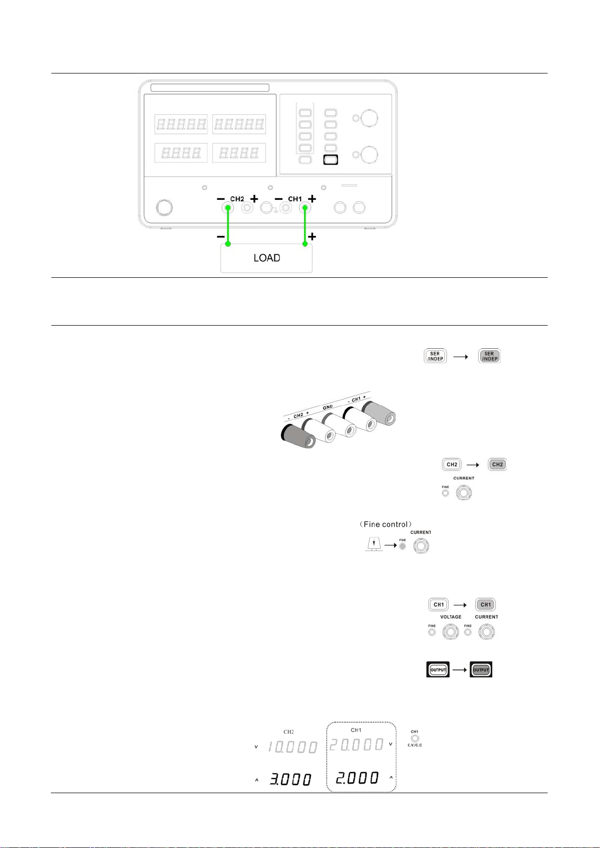
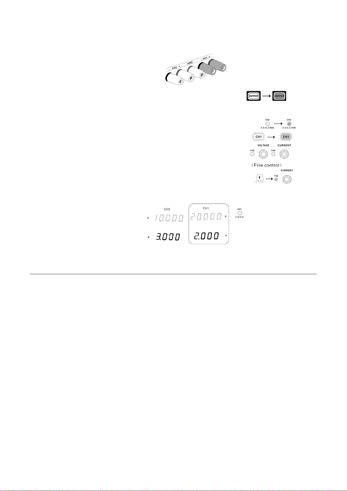
3.3 CH1/CH2 Tracking Series Mode
Background Tracking series operation doubles the Voltage capacity of the power supply series by internally
connecting CH1 (Master) and CH2 (Slave) in series and combining the output to a single channel.
CH1 (Master) controls the combined Voltage output level.
The following describes two types of configurations depending on the common ground usage.
- 11 -
Tracking series without common terminal
Connection
Output rating 0~60V/0~3A (I≤3A)
0~60V/0~5A (I>3A)
Panel operation 1. Press the SER/INDEP key to activate the tracking series mode.
The key LED turns on.
2. Connect the load to the front panel terminals, CH1+ & CH2-. (Single supply).
3. Press the CH2 switch (LED turns on) and use the Current knob to set
the CH2 output current to the maximum level. By default, the
Voltage and Current knob work in the coarse mode. To activate the
fine mode, press the knob and turn on the FINE LED.
Coarse: 0.1V or 0.1A @ rotation click.
Fine: the smallest digit @ rotation click.
4. Press the CH1 switch (LED turns on) and use the Voltage and
Current knob to set the output voltage and current level.
5. To turn on the output, press the output key. The key LED turns on.
6. Refer to the CH1 (Master) meter and indicator for the output setting level and CV/CC status.

- 12 -
Voltage level Double the reading on the CH1 Voltage meter. In the above case, the actual output is 20.0 x 2=
40.0V.
Current level CH1 meter reading shows the output Current. In the above case, 2.000A. (CH2 Current control must
be in the Maximum position=3.0A(I≤3A) or 5.0A(I>3A)).
Tracking series with common terminal
Connection
Output rating 0~30V/0~3A for CH1~COM (I≤3A) 0~30V/0~5A for CH1~COM (I>3A)
0~-30V/0~3A for CH2~COM (I≤3A) 0~-30V/0~5A for CH2~COM (I>3A)
Panel operation 1. Press the SER/INDEP key to activate the tracking series mode.
The key LED turns on.
2. Connect the load to the front panel terminals, CH1+/- & CH2-. Use the CH1 (-) terminal as the
common line connection.
3. Press the CH1 switch (LED turns on) and use the Voltage knob
to set the master & slave output voltage (the same level for both
channels). By default, the Voltage and Current knob work in
the coarse mode. To activate the fine mode, press the knob
and turn on the FINE LED.
Coarse: 0.1V or 0.1A @ rotation click.
Fine: the smallest digit @ rotation click.
4. Use the current knob to set the master output current.
5. To turn on the output, press the output key. The key LED turns on.
6.
For the master (CH1) output level and CV/CC status, refer to the CH1 meter and indicator.

- 13 -
Master (CH1) voltage level: CH1 meter reading shows the output voltage. In the above case,
20.0V.
Master (CH1) current level: CH1 meter reading shows the output current. In the above case,
2.000A.
7. Press the CH2 switch (LED turns on) and use the Current knob to set the
slave output current.
8. For the slave (CH2) output level and CV/CC status, refer to the CH1/2 meter and CH2 indicator.
Slave (CH1) voltage level: CH1 meter reading shows the output voltage. In the above case,
20.0V.
Slave (CH1) current level: CH1 meter reading shows the output current. In the above case,
2.000A.
3.4 CH1/CH2 Tracking Parallel Mode
Background/
connection
Tracking parallel operation doubles the current capacity of the power supply series by internally
connecting CH1 and CH2 in parallel and combining the output to a single channel. CH1 controls the
combined output.
Output rating 0~30V/0~6A (I≤3A)
0~30V/0~10A (I>3A)
Panel operation 1. Press the PAR/INDEP key to activate the tracking parallel mode.
- 14 -
The key LED turns on.
2. Connect the load to the CH1 +/- terminals.
3. To turn on the output, press the output key. The key LED turns on.
4. The CH2 indicator turns red, indicating tracking parallel (PAR) mode.
5. Press the CH1 switch (LED turns on) and use the Voltage and
Current knob to set the output voltage and current. The CH2
output control is disabled. By default, the Voltage and Current
knob work in the coarse mode. To activate the fine mode, press the
knob and turn on the FINE LED.
6. For the output level and CV/CC status, refer to the CH1 meter and indicator.
Voltage level: The CH1 meter reading shows the output voltage. In the above case, 20.0V.
Current level: Double the amount of CH1 current meter reading. In the above case,
2.0A x 2 = 4.0A.
- 15 -
4. SAVE/RECALL SETUP
4.1 Save Setup
Background
The front panel settings can be stored into one of the four internal memories.
Programming
contents
The following list shows the programming setting contents:
Independent / tracking series / tracking parallel mode
CH1/CH2 knob selection
Fine/coarse knob editing mode
Beep on/off
Output voltage/current level
The following settings are always saved as “off”:
Output on/off
Front panel lock on/off
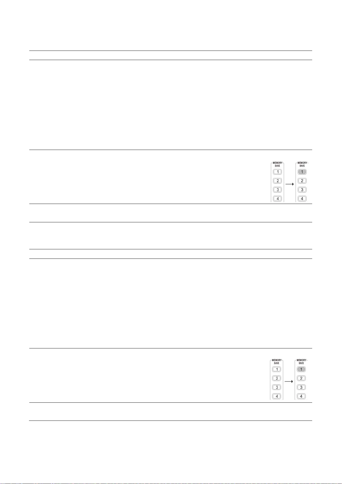
Panel operation Press one of the 1~4 Memory keys for 2 seconds, for example memory 1. The
panel settings will be saved in memory 1 by long push to this key and the key
LED turns on. When the panel settings are modified, the LED turns off.
Note When the setting is stored, the output automatically turns off.
4.2 Recall Setup
Background
The front panel settings can be recalled from one of the four internal memories.
Programming
contents
The following list shows the programming setting contents:
Independent / tracking series / tracking parallel mode
CH1/CH2 knob selection
Fine/coarse knob editing mode
Beep on/off
Output voltage/current level
The following settings are always recalled as “off”:
Output on/off
Front panel lock on/off
Panel operation Press one of the 1~4 Memory keys, for example memory 1. The panel settings
saved in memory 1 will be recalled by pressing this key. The key LED turns on.
When the panel settings are modified, the LED turns off.
Note
When a setting is recalled, the output automatically turns off.
- 16 -
5. REMOTE CONTROL
5.1 Remote Control Setup
Background
The power supply is capable of being remotely controlled via the USB connection.
Interface USB slave port, rear panel
COM setting Set up the COM port inside the PC according to the following list:
Baud rate: 9600
Parity bit: None
Data bit: 8
Stop bit: 1
Data flow control: None
Functionality check Run this query command via the terminal application such as MTTTY (Multi-threaded
TTY).
*IDN?
This should return the identification information: series number, firmware version.
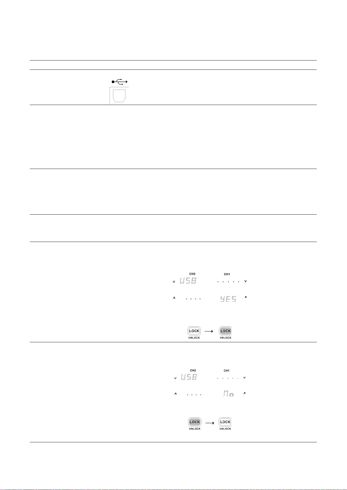
5.2 Remote Connection Step
Enter the remote control
mode
1. Connect the USB cable to the slave port.
2. The connection will be automatically established, and the front panel shows
“USB…YES” message.
3. The power supply also automatically enters the lock state (the Lock key will be
activated).
Exit the remote control
mode
1. Disconnect the USB cable from the rear.
2. The display shows “USB…NO” message.
3. Unlock the power supply by pressing the Lock key until it turns off backlight.
4. The power supply goes back to local operation mode.

- 17 -
5.3 Command Syntax
Command format
1: command header
2: output channel
3: separator
4: parameter
Parameter Type
<Boolean>
<NR1>
<NR2>
Description
Boolean logic
Integers
Decimal numbers
Example
0 (off), 1 (on)
0, 1, 2, 3
0.1, 3.14, 8.5
Output channel
1 (CH1) or 2 (CH2)
Note Commands must be capital letters
5.4 Error Messages
The following error messages might appear when the power supply cannot accept the command.
Message contents
Descriptions
a
Program mnemonic too
long
The command length must be 15 characters or less.
b
Invalid character
Invalid characters, such as symbols, are entered. Example: VOUT#
c Missing parameter The parameter is missing from the command. Example: VSET: (should
have a number)
d Data out of range The entered value exceeds the specification. Example: VSET:33 (should
be≤32V)
e Command not allowed The entered command is not allowed in the circumstance. Example: trying
to set CH2 output while in the tracking mode.
f Undefined header The entered command does not exist, or the syntax is wrong.
5.5 Command List
Detailed descriptions of each command starts from the next page.
The “HELP” command shows all the following commands and their meanings, except for the HELP command itself.
Command
Meanings
ISET<X>:<NR2>
Sets the output current
ISET<X>?
Retunes the output current setting
VSET<X>:<NR2> Sets the output voltage
VSET?
Returns the output voltage setting
IOUT<X>? Returns the actual output current
VOUT<X>?
Returns the actual output voltage
TRACK<NR1>
Selects the operation mode
BEEP<BOOLEAN> Turn on or off the beep
OUT<BOOLEAN>
Turn on or off the output
STATUS? Returns the MODEL status
Table of contents


