Twitoplast OPAL RC-11 User manual

OPAL RC-11
Operating
And Manual
instructions

congratulates you on your purchase of the remote control and receiver for
the proportional damper. The is part of a smart system that controls the temperature
measurement in one room. The system was designed by the company’s engineers
for quick and easy installation and optimum performance to assure perfect and uniform air
conditioning.
Contents:
Part 1 - Before Installation
Part 2 - Installation of & Receiver for the Proportional
Damper and Connecting to the Power Supply Box
Part 3 - Checking regularity of the System
Part 4 - Characteristics
Part 5 - Operating Instructions and Functions of the Buttons
Remote control for
the proportional
damper :
1
Page
2-3
4-5
6
7
8-15

1. Before Installation
1.1 Auxiliary Equipment
1.1.1 Power Supply Unit Type C315 (not included)
The remote control must be used only with a C315 power supply box.
1.1.2 Cable with Quick Connection Connector (cable 140106 included)
The following standard length cables with quick-connecting connectors between the receiver and the
power Supply Box may be used with:
1.2 Alternative System Configurations.
The system enables to connect up to four remote controls and dampers to one power supply box and
thus provides flexibility and comfort in installation according to the requirements on site. The connection
possibilities are detailed as follows:
Type No. of channels Supply
C315 1 One remote control
C315
›
2 2 Up to 2 remote controls
C315
›
4 4 Up to 4 remote controls
Length Code
6 m 140106
10 m 140110
15 m 140115
20 m 140120
Two Channels
Connection of up to two remote controls
to one Power Supply Box C315 - 2
And up to two dampers.
One Channel
Connection one remote to one Power Supply Box
C315 and one damper.
230
Volt (V)
230
Volt (V)
2

RJ-11
RJ-11RJ-11
Four Channels
Connecting of up to four remote controls
To one Power Supply Box C315 - 4
And up to four dampers.
1.3 Warning for Safe Installation
-Before starting to work, make sure that the power supply cable is disconnected from the 220v electrical
network!
-The installations must be carried out by a qualified electrician or a certified technician.
-For the connection between the receiver and the power supply box, use only cables with quick-
connecting connectors, supplied by the manufacturer.
-The connection to the supply voltage must be carried out only with a standard cable to the end of
which a standard connector has been connected.
Two Units One Channel
Connecting one remote control
To two Power Supply Boxes and two dampers (in a similar way
3 power supply boxes and dampers can be connected)
230
Volt (V)
230
Volt (V)
230
Volt (V)
Distributor
3
BEFORE STARTING TO WORK...

2.2 Connecting to the Power Supply Box
2.2.1 Power Supply Box Location
-Connect the power supply box to the air conditioner or to the wall using four screws. the power supply
box should be accessible for service .
2. Installing the RC- 10 & Receiver to the Power Supply Box
RJ11
2.1 Installation of the receiver and remote control holders
2.1.1 Installation of the remote control holder
-Choose a location for the holder, considering the customer’s requirements
-Install the remote control holder in air conditioned environment on a
spot, where the temperature can be detected best.
-Height of 1.5 m above the floor is recommended.
The holder should not be installed on an external wall, near a stairway,
or an area that is exposed to the external temperature, (radiation from
the sun, heating elements, air pocket etc.). The remote control holder
should be installed under the receiver. It can also be installed in another
place only in a straight visual line from the receiver. For the installation
of the remote control holder, use two screws.
2.1.2 Installation of the receiver C612 (the receiver should not be opened.)
-The receiver has to be installed close to the ceiling, or in a location considering the requirement of
the customer. Ensure that the receiver will be at a visual line from the
remote control holder.
-In order to install the receiver, mark the screw locations on the wall with the measurable tag provided..
-Apply one dowel pin, apply the screw via the holding device and tighten the screw fastening the
holder to the wall as much as possible. Plug the RJ-11 wire into the socket on the side of the receiver.
Adjust the receiver according to the markings and fasten it to the holding device (until you hear a
“click”).
WARNING: The Power Supply Box must not be installed close to lighting accessories or where it is
exposed to water and humidity.
Screw Screw
Pin
Pin
Pin
Remote
Control
Holder
Remote
Control
Holder
4

2.2.2 Connecting the Power supply box to the Receiver
-Mark the cable with the snap connection (RJ
›
11) with a color sticker “flag” (stickers provided with
the power supply box).
-Connect the receiver to the power supply box using a cable with a quick-connection (RJ
›
11).
-Connect the power supply box to the damper motor with a multiple line flexible cable.
Connection of the receiver to the power supply box: C315
›
4 four channels
Connection diagrams:
Connection details:
Receiver connection
Connection to motor
Damper motor Power supply box Receiver
T1
T2
T3
T4
+ -
+ -
+ -
+ -
D1- D1+
D2- D2+
D3- D3+
D4+ D4+
T1
T2
T3
T4
Connection of the receiver to the power supply box: C315
›
1 one channel
Connection of the receiver to the power supply box: C315
›
2 two channels
5
Cable
Code
Code
Code
Power Supply Box
Power Supply Box
Power Supply Box
4 Channels
2 Channels
One Channel
Cable
Motor
zero
Phase volt
zero
Phase volt
Motor
Motor
Motor Motor
Motor
Motor
zero
Phase volt
Cable
Cable

Make sure the remote control is not off.
1. Make sure no crossing of connections of the receiver or damper took place, e.g. receiver
no. 1 was connected to inlet T1 and the damper is connected to inlet D2+ and D2-.
2. Make sure the connections of the receiver to the power supply box are orderly (see solution
no. 2).
3. If the connections were checked and were OK as detailed above, operate the damper with
the AUTO button on the receiver. If the damper reacts, check the batteries in the remote
control.
3. Checking the Proper Installation of the System
3.1.1 Connections
Ascertain:
- Receiver no. 1 (T1) is connected to entry no. 1 (T1) and motor no. 1 (T1) is connected to terminals D1 +, D1
›
- Receiver no. 2 (T2) is connected to entry no. 2 (T2) and motor no. 2 (T2) is connected to terminals D2 +, D2
›
- Receiver no. 3 (T3) is connected to entry no. 3 (T3) and motor no. 3 (T3) is connected to terminals D3 +, D3
›
- Receiver no. 4 (T4) is connected to entry no. 4 (T4) and motor no. 4 (T4) is connected to terminals D4 +, D4
›
- With the connection of the power supply box to line voltage ensure that the red indicator light on the power
supply box is on.
-Wait 70 seconds and switch the remote control off. Make sure that the damper is switched off (closed). In case
the damper is open, cross the two wires that reach the motor or the two wire connections +D and
›
D.
- Move between status 1/3 and 2/3 and make sure the damper actually moves.
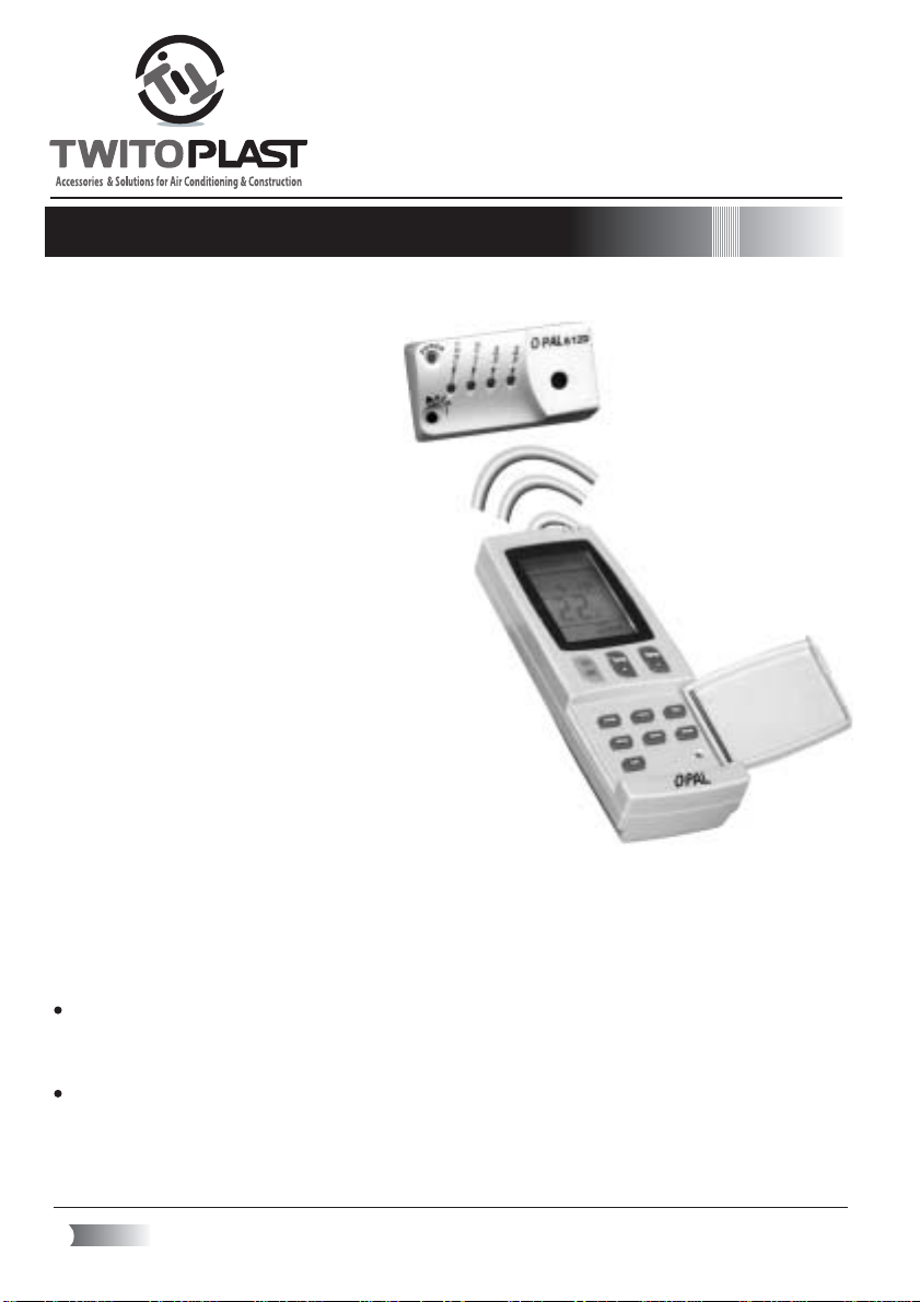
3.1.2 Communication between Remote Control and Receiver.
- When finishing the installation of the receiver and the holder of the Remote Control unit, try to activate the
receiver with the remote control when it is still in the holder.
- On the remote control press the ON button and check whether the red light on the receiver is blinking. The
blinking of the red on the Receiver informs that, the receiver absorbed the transmission from the remote control.
- In case there is no red light blinking on the receiver, change the required temperature on the remote control
and/or transfer the operational status from heating to cooling. Then check once again if the red lamp is blinking
in the receiver. If the receiver is not blinking, change the location of the remote control holder.
- Make sure to explain to the customer that the place for the remote control is in the holder unit. Keeping the
remote control in the holder, ensures the constant reception of reliable signals and enables a correct operation
of the system. In addition, this ensures the remote control will not be damaged.
3.2 Troubleshooting
Problem Solution
The indicator lamp on the
power supply box is not on
Check for 230 V electricity outlet.
1.Check that the connection of the power supply box to the 230v.
No ON/STBY indicator
on the receiver is alight.
The damper does not
react in spite of switching
from 1/3 to 2/3 and
changing the MODE
(heating / cooling)
1. Make sure that the snap connections are connected properly to the receiver and to the power
supply box.
2. Ensure that the indicator light in the power supply box is on, if not see solution to problem
6

4.1 Remote Control Character
- Rigid plastic body
- Digital LCD display for activity status
- Digital temperature display for actual and desired temperature
- Operates at 3V potential - with (AAA) batteries
- The temperature adjustment range is from 10 ∞C to 30 ∞C
- Accuracy is ±1˚C
- Includes an internal temperature receiver
- Operates on heating and cooling
- Manual or Automatic mode
4.2 C315 Power Supply Box Characteristics
- Fire proof plastic V0
- Protection against voltage drop in the supply network
- Nominal voltage: 230 V AC (50
›
60 Hz)
- Exit voltage of 12 V
- Light indicator operation
- Relative Humidity: RH = 10% - 90%
- Constructed according to UL/IEC Standard
- Dimensions: 60 x 78 x 125 mm
4. Characteristic
7

Before activating:
Make sure that the power supply
box is connected to the power
120v AC and that the green led in the
C315 power supply box is on.
BATTERIES REPLACMENT AND REAL TIME
CLOCK SETTING.
Slide down the batteries cover that is located at the
back of the remote control. Insert two 1.5V sizeAAA
batteries.
After placing the batteries, the real time clock on the
display (10) will blink 0:00. Set the actual time by pressing
the +/- buttons (2).when the digits show the real time,
press SET (14) for setting the time.
The real time clock can also be set using the CLOCK button
(12) and then the same procedure using the +/- buttons (2)
and SET (14).
Please, pay attention to the following
The remote control signal can be received at a distance of up to 7 meters.
Communication between the Remote control and the I.R receiver is done
via infrared signal. Therefore, the Remote control should always be aimed
directly at the I.R receiver, without any obstructions.
Neither the Remote control nor the I.R Receiver should be exposed to direct
sun light or florescent light or any heat source.
Using the RC-11 to Activate the Proportional Damper
8

On / OFF button.
Temperature & time Up / Down buttons.
Damper Mode selection Button.
Operation Mode selection button.
Operation Mode Display.
Set Temperature Display.
Room Temperature icon.
Low battery icon.
Sleep mode icon.
Real time clock Display.
ON & off Timers Display.
Real time clock button.
Timer select button.
Timer Set button.
Room temperature button.
Reset Button.
Sleep Button.
Transmission Icon.
Temperature sensor.
± ≤
≥
¥
µ
∑
∏
π
∂
±≥
±≤
±±
±∞
±¥
±µ
±∂
±∑
±∏
±π
HOW TO USE THE REMOTE CONTROL
9
≤∞

TURNING THE DAMPER ON & OFF
Press On/Off button (1) to turn on & off the Damper unit.
When pressing on, the Power and the Heat Or Cool
indicators on the I.R receiver will light.
Pressing the On/Off button (1) again, will close the Damper
and turn of the LCD display and the lights on the I.R receiver.
The Damper unit will always work at the last mode of
operation.
SELECTING THE MODE OF OPERATION
Pressing the OPERATION MODE button (4) will
determine the Mode. The MODES are:
COOL- Cools, dehumidifies the room air. Maintains
desired room temperature. Cool indicator on the I.R
receiver will light.
HEAT- Heats the room air. Maintains desired room
temperature. heat indicators on the I.R receiver will light.
The OPERATION MODE should be always the same as the
OPERATION MODE of the A.C. Unit
The OPERATION MODE selected will be shown on the
operation mode display (5).
DAMPER MODES
Pressing the FAN button (3) will determine the Damper Mode:
MANUAL MODE 1 - In this mode the damper is open
constantly to 1/3 of the maximum air supply.
The LCD display will show and the + / - buttons
will be inactive.
MANUAL MODE 2 - In this mode the damper is open
constantly to of the maximum air supply.
The LCD display will show
and the + / - buttons will be inactive.
MANUAL MODE 2- In this mode the damper is fully
opened.
The LCD display will show and the + / - buttons
will be inactive.
UTO MODE - InAUTO MODE the Damper is opened
in accordance with the difference between the desired
(set) and the room temperature.
10

11
SETTING THE DESIRED TEMPERATURE
To set the desired temperature press the Temperature & time
UP / DOWN buttons (2).
Setting the desired temperature is possible only inAUTO damper mode.
While the damper is in MANUAL mode the + / - buttons are inactive.
ROOM TEMPERATURE
Pressing the ROOM button (15) will show the room temperature,
the room icon will be shown. Pressing the room button once again
will show the set temperature .
SLEEP MODE
This mode is designed to create comfortable sleeping conditions.
Pressing the sleep button (17) will activate the sleep mode.
In this mode when the DAMPER unit is in heating mode, the desired
temprature will decrease in one degree every hour for three hours.
When the DAMPER unit is in cooling mode, the desired temprature
will increase in one degree every hour for three hours.
RESET BUTTON
Pressing the RESET button (16) will return all the definitions of the
Remote Control back to the default status.

12
SETTING ON & OFF TIMERS
Pressing the TIMER button (13) activate the timer opeartion mode.
Each time the timer button (13) is pressed, it changes the timer
operation mode. There are 3 timer opeartion mode:
TIMER ON-This mode sets a time for starting the operation of the
Damper
TIMER OFF- This mode sets a time for stopping the operation
of the Damper
Press SET button(14)
to activate the timer.
To set the ON timer press TIMER
button (13). The ON icon on the
ON & OFF Timers Display (11)
will blink .Pressing the +/- buttons
will adjust the starting time
respectively
Press TIMER button (13) once
again. The OFF icon on the
ON & OFF Timers Display (11)
will blink. .Pressing the +/-
buttons will adjust the stopting
time respectively.
To set the ON timer press TIMER
button (13). The ON icon on the
ON & OFF Timers Display (11)
will blink.
Press SET button(14) to
activate the timer.

13
TIMER ON & OFF - This mode enables setting the start and
stop time of operation of the Damper
NOTE: To cancel the timers operation press TIMER button (13) until the ON or OFF icons are not
shown on the LCD display.
All the timers are cyclic
Press TIMER button (13) once again.
The OFF icon on the ON & OFF Timers
Display (11) will blink.
To set the ON and OFF timers
press TIMER button (13)
The ON icon on the ON & OFF
Timers Display (11) will blink.
Press TIMER button (13) again.
The OFF icon on the ON & OFF
Timers Display (11) will blink. And the
ON icon will be shown. Pressing the
+/- buttons will adjust the starting time
respectively.
Press TIMER button (13) again.
The ON icon on the ON & OFF Timers
Display (11) will blink. And the OFF
icon will be shown. Pressing the +/-
buttons will adjust the starting time
respectively.
Press SET button(14) to
activate the timer.
STEP 1 STEP 2
STEP 3 STEP 4
STEP 5

14
ID CODE
Assigning ID CODE to the remote control, enable distinguishing
between remote controls that are placed nearby.
When two or more remotes are placed near by there is a chance
that the I.R transmission from one remote will be received by the
wrong I.R receiver
Pressing simultaneously the MODE & ROOM button for more
than 6 seconds, while the remote control is On, will allow entering
the ID CODE setting of the remote. The LCD will show 00 blinking.
By pressing + / - the code is selected .The ID CODE range is
from 00 to 08. Pressing SET button will store the ID CODE and
the display is back to normal operation with the last temperature.
If the SET button is not used for over 6 sec from last button press,
the modification shall be canceled automatically and recover the
normal operation with the original ID code (the one used before
entry to the modify mode).
When replacing the batteries the E set again ID COD.!!!
BATTERIES LOW
When batteries are low, the LOW BAT icon will be shown. Replace the
old batteries with new AAA batteries (Alkaline).
Set clock as mentioned above.

±
≤
≥
¥
µ
∑
∂
±≤
≥¥
µ
∂
∑
The I.R receiver includes leds that represent the mode of operation and a button that enable operating
the DAMPER unit.
THE I.R RECEIVER
COOL LIGHT (LED)
The COOL light indicates that the DAMPER unit is operating in cool mode. Recieving signal
from the Remote control is indicated by a blinking of the light(led).
HEAT LIGHT (LED)
The HEAT light indicates that the DAMPER unit is operating in heat mode. Recieving signal
from the Remote control is indicated by a blinking of the light(led).
1/3 LIGHT (LED)
The ? light indicates that the DAMPER unit is operating in MANUAL mode and the DAMPER
is ? open. Recieving signal from the Remote control is indicated by a blinking of the light(led).
2/3LIGHT (LED)
The ? light indicates that the DAMPER unit is operating in MANUAL mode and the DAMPER
is ? open. Recieving signal from the Remote control is indicated by a blinking of the light(led).
When the ? light and the ? light are lighting together, it indicates that the DAMPER is fully
opened.
POWER ON/OFF LIGHT (LED)
The POWER light indicates that the DAMPER unit is ready to operate. When the light is off the
DAMPER is Closed.
AUTO BUTTON
Auto button enables operating the DAMPER unit when the remote control is missing OR when
the batteries are low. Pressing the button while the DAMPER button is OFF, will move the damper
from off to on positions ?, ? , full opening and then back again to to close position.
I.R RECEIVER
Receive signal from the Remote Control.
15
OPAL 612D

Notes
16

Additional Producte In This Series: km
Mechanical kit for modular Damper
OPAL EL - Electronic Dimmer control for proportional Modular Damper
OPAL C-128DD - Wall mounted thermostat for propotional
Modular Damper
OPAL 650DD Flush Mount - Electronic Thermostat for
Propotional Modular Damper
OPAL C-210RF-Wall Thermostat (Radio Frequency for
proportional Modular Damper)
Tel: +972-3-9345888, Fax: +972-3-9042729 | www.twitoplast.co.il | E-mail: [email protected]

Also Available
OPAL EL
Opal – 680 RF
OPAL RC 11
Opal -650DD
Table of contents