TXT MX VTX-58 PRO HV Series User manual

MX VTX-58XX PRO HV Series Video Transmitter
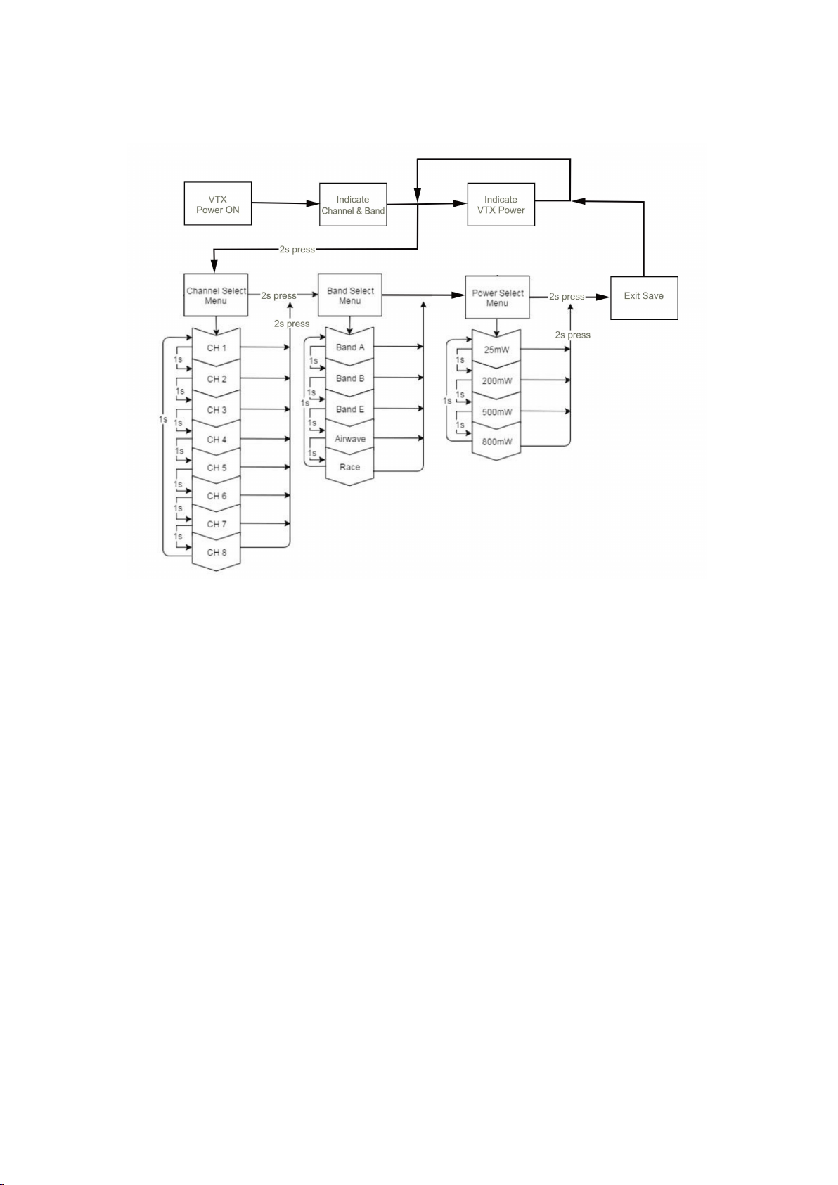
Button Operation:
The button on VTX board has three functions or use ways: set up channel, set up frequency band,
set up VTX power. Connect VTX with power, wait till the LED finishes indicating the present working
frequency, long press the button(SW) 2 seconds, VTX will enter set up menu, two of the LED will
show the present menu state. The exact operation will be as the following:
1)Set up channel(Channel): long press button(SW) for 2 seconds till the blue LED is turned on,
then release the button, entering channel set up mode(red LED flashes one time), select channel
by short pressing the button(SW)----times of the blue LED flashes indicating the current channel
value;
2)Set up channel group (Band): long press button(SW) 2 seconds till blue LED light is on, then
release the button(SW), it enters channel set up mode(red LED flashes two times), short press the
button(SW), select channel group(Band)----times of the blue LED flashes indicating the value of
current channel group(Band).
3)Set up transmitting power: long press button(SW) 2 seconds till the blue LED light is on, then
release the button(SW), it enters set up channel mode(red LED flashes 3 times), select power by
short pressing button(SW)---times the blue LED flashes indicating the current value of power.
4)Exit and save: long press the button (SW) 2 seconds till blue ELD is on, then release the
button(SW), after red and blue LED flashes in turn for 5 times, VTX logs out of set up mode, the
changed parameters are saved.
Note:
1) The above operation should only be in 1),2),3),4) order.
2) The transmitting power will be 25mW automatically when VTX enters set up mode, and VTX will
return to the already setup power when VTX exits set up mode.
3) When manually control power function is in use, the power of VTX will follow the manually
controlled power. When manually control power function is not in use, the working power of VTX will
be decided by the setup power of VTX.

Structure of button press menu

SmarAudio Protocol:
SmartAudio protocol is a convenient operation for setting up VTX working frequency and power on
OSD display through radio, it is a solution for connection between VTX and flight control board.,
which is very simple and direct way.
For using this function, please connect RXD on VTX to TXD on UART3 or UART6 of flight control
board first, turn on SmartAudio function on flight control board as the following:
Then enter set up mode according to guided message on OSD, and enter set up menu for VTX,
VTX will save the data automatically as soon as the setup is effective(red and blue LED flashes 6
times in turn).

Indication for VTX working frequency and power:
LED flashing state indicates current working frequency when VTX is powered. Circulated flashing
blue LED indicates the current transmitting power of VTX after VTX working frequency is indicated.
● Red and blue LED flashing state indicates the current working frequency of VTX at the time VTX
is powered.
● Circulated flashing blue LED(red LED is solid bright) indicates the current transmitting power of
VTX.

LED Indication function:
MX VTX-58XX PRO HV indicates different working state through two color LED lights which is
simple and efficiency. Flashing times of red LED indicates different option, flashing one time
indicates Channel, flashing two times indicates Band, flashing three times indicates power.
Flashing times of blue LED indicates the value of the option.
Red LED
Option:(Channel),(Band), VTX power
Blue LED
value of the option
Example: Channel 5, Band B, 500mW power, the LED flashes like the following:
● 1x Red & 5x Blue = Channel, 5
● 2x Red & 2x Blue = Band, 2 (=B)
● 3x Red & 3x Blue = Power, 3 (= 500mW)
Menu table:
Red LED
Blue LED
1*
2*
3*
4*
5*
6*
7*
8*
1*
Channel
1
2
3
4
5
6
7
8
2*
Band
A
B
E
Airwave
Race
3*
Power
25mW
200mW
500mW
800mW
Frequency table:
Channel
1
2
3
4
5
6
7
8
Band A
5865
5845
5825
5805
5785
5765
5745
5725
MHz
Band B
5733
5752
5771
5790
5809
5828
5847
5866
MHz
Band E
5705
5685
5665
5645
5885
5905
5925
5945
MHz
Airwave
5740
5760
5780
5800
5820
5840
5860
5880
MHz
Race
5658
5695
5732
5769
5806
5843
5880
5917
MHz
Power
25mW
200mW
500mW
800mW
(The selections in yellow requires HAM license to operate legally. The video transmitter ensures
that you cannot select illegal channels or power levels by accident:)

Ports description (marked at the back of the board)

Note: A0 gets two functions: GND and PWM, when A0 at the back of the board is connected with
GND port, the manually power control function will be terminated, as a result, A0 functions GND.
Manually power real time control:
Manually power real time control is for adjusting transmitting power of VTX manually according to
distance between transmitter and flying model, through which VTX can be less power consumption
and less interference to other pilots at the scene. Transmitting power of VTX is decided by
(button)SW set up or by the setup value of SmartAudio protocol if manually power control function
is not in use.
The manually power control function changes VTX power according to standard servo signal
(1.0~2.0Ms). When signal is added to A0 pin, MCU on VTX changes VTX power accordingly
through checking signal width, blue LED flashing times indicates the current power.

Matchup table between blue LED flashing times and VTX power:
Blue LED
Times
1*
2*
3*
4*
Power
25mW
200mW
500mW
800mW
Matchup table between standard servo signal(1.0~2.0Ms) and VTX power:
VTX-5808 PRO-A HV
VTX-5804 PRO-A HV
VTX-5805 PRO-B HV
Power
Standard servo signal(1.0~2.0mS)
25mW
A0-t<1.2mS
A0-t <1.2mS
A0-t <1.2mS
200mW
1.2 mS < A0-t <1.6mS
A0-t >1.2 mS
1.2 mS < A0-t <1.8mS
500mW
1.6 mS < A0-t <1.8mS
NC
A0-t >1.8 mS
800mW
A0-t >1.8 mS
NC
NC
Note: A0-t indicates the time of high level when standard servo signal inputs A0 port. NC means
nothing for the VTX.
Example for manually power real time control:
Set up one signal channel A on receiver or on flight control board as standard servo signal output
mode ( on CLI mode), connect signal A to A0 port on VTX, set up corresponding channel for signal
A onto a 3-gear switch on transmitter, when the 3-gear switch on transmitter is pulled, flashing
times of the blue LED will be changed indicating the current transmitting power.
For MX VTX-5808 PRO-A HV with 4 transmitting power options, you can’t use a 3-gear switch for
setting up the value of 4 transmitting power options, customer can set up corresponding channel for
signal A onto a VR potentiometer channel, or set up 2.0ms as the highest value for getting
800Mw(no use for 500mW) power on the 3-gear switch(the corresponding channel for A) on the
transmitter, or set up 1.7ms as the highest value for getting 500Mw(no use for 800mW) power on
the 3-gear switch(the corresponding channel for A) on the transmitter. Customer can figure out the
highest value of transmitting power according to LED flashing times by pulling 3-gear switch.
Installation:
MX VTX-58XX PRO HV serial video transmitters have mounting holes on the board, customer can
install it by screws for FPV multirotor. Customer can install it by 3M tape on fixed-wing FPV
airplane.
This manual suits for next models
3
Table of contents
Popular Extender manuals by other brands

D-Link
D-Link DAP-1620 Quick install guide

Shenzhen Shunxun Electronics
Shenzhen Shunxun Electronics SX-EHU100 Operating instruction

zBoost
zBoost SOHO Xtreme YX545x Setup manual

Gefen
Gefen DVI-3000HD user manual

Smart Cabling & Transmission
Smart Cabling & Transmission HW02 user manual

R&S
R&S SMW-K550 user manual