TYAN S5372-LH User manual

1
Tempest i5000VS /// S5372-LH
Version 1.0
Copyright
Copyright © TYAN Computer Corporation, 2007. All rights reserved. No part of
this manual may be reproduced or translated without prior written consent from
TYAN Computer Corp.
Trademark
All registered and unregistered trademarks and company names contained in
this manual are property of their respective owners including, but not limited to
the following.
TYAN, Tempest i5000VS are trademarks of TYAN Computer Corporation.
Intel, 5000V, and combinations thereof are trademarks of Intel Corporation.
Phoenix, Phoenix-Award BIOS are trademarks of Phoenix Technologies.
Notice
Information contained in this document is furnished by TYAN Computer
Corporation and has been reviewed for accuracy and reliability prior to printing.
TYAN assumes no liability whatsoever, and disclaims any express or implied
warranty, relating to sale and/or use of TYAN products including liability or
warranties relating to fitness for a particular purpose or merchantability. TYAN
retains the right to make changes to product descriptions and/or specifications
at any time, without notice. In no event will TYAN be held liable for any direct or
indirect, incidental or consequential damage, loss of use, loss of data or other
malady resulting from errors or inaccuracies of information contained in this
document.

2
Table of Contents
Check the box contents! 3
Chapter 1: Introduction
1.1 Congratulations 5
1.2 Hardware Specifications 5
Chapter 2: Board Installation
2.1 Board Image 8
2.2 Block Diagram 9
2.3 Board Parts, Jumpers and Connectors 10
2.4 Tips on Installing Motherboard in Chassis 18
2.5 Installing the Processor(s) 19
2.6 Installing the Memory 22
2.7 Attaching Drive Cables 24
2.8 Installing Add-in Cards 26
2.9 Connecting External Devices 27
2.10 Installing the Power Supply 28
2.11 Finishing up 28
Chapter 3: BIOS Setup
3.1 About the BIOS 29
3.2 BIOS Main Menu 31
3.3 Advanced Menu 39
3.4 Security Menu 57
3.5 Power Menu 58
3.6 Boot Menu 60
3.7 Exit Menu 61
Chapter 4: Diagnostics
4.1 Beep Codes 63
4.2 Flash Utility 63
4.3 Phoenix BIOS Post Code 64
Appendix: SMDC Information 67
Glossary 69
Technical Support 77

3
Check the box contents!
1x S5372-LH motherboard
1 x Ultra-DMA-133/100/66/33 IDE cable
2 x Serial ATA power cable
4 x Serial ATA Cable
1 x USB2.0 cable
1 x S5372-LH user’s manual
1 x S5372-LH Quick Reference guide
1 x TYAN driver CD
1 x I/O shield
2 x CPU Back Plane
If any of these items are missing, please contact your vendor/dealer for
replacement before continuing with the installation process.

4
NOTE

5
Chapter 1: Introduction
1.1 - Congratulations
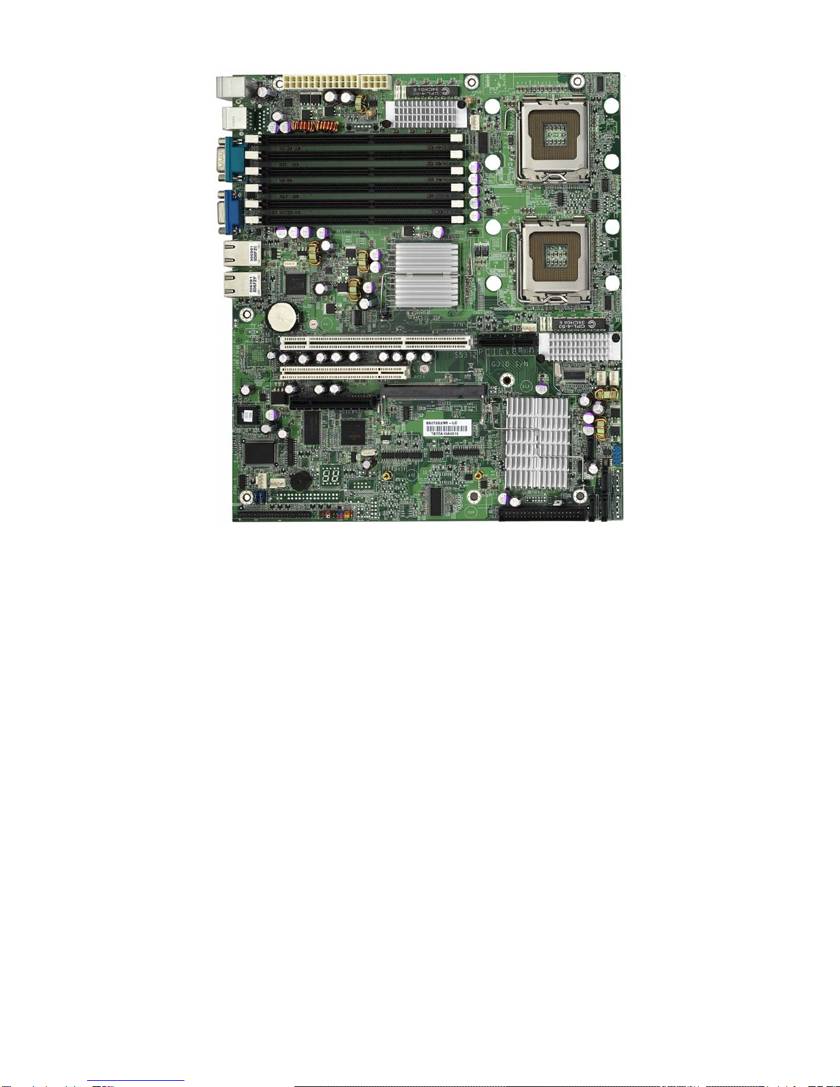
You have purchased one of the most powerful server solutions. The Tempest
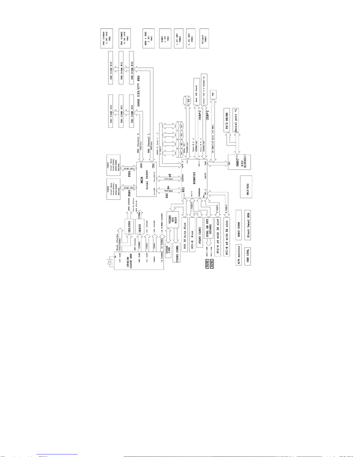
i5000VS (S5372-LH) is a flexible Intel®platform for multiple applications, based
on Intel®5000V MCH and ESB6321 chipsets.
Designed to support Intel®Xeon 5100/5200/5300/5400(80W or lower)
processors and DDR2-533/667 FB-DIMM memory, and featured with integrated
Dual Gigabit Ethernet LAN, built-in 16MB XGI XG20TM video plus four serial
ATA ports, the S5372-LH offers exceptional performance and versatile solution
for your server platform.
Remember to visit TYAN’s Website at http://www.TYAN.com. There you can
find information on all of TYAN’s products with FAQs, online manuals and BIOS
upgrades.
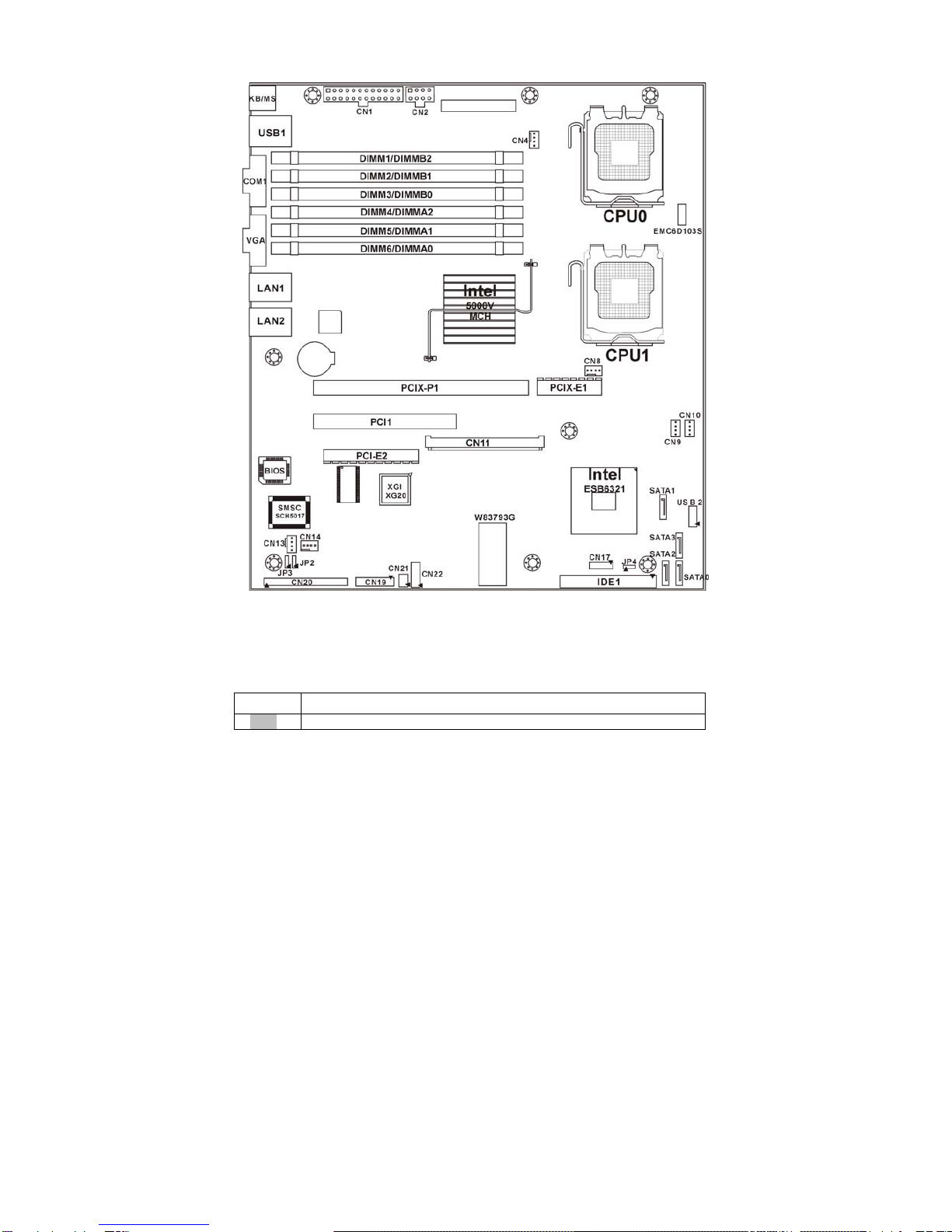
1.2 – Hardware Specifications
Processors
•Dual LGA771 sockets
•Supports up to two (2) Intel® Xeon
5100/5200/5300/5400 series
processors
- Intel Xeon CPU support for 80W
CPU or lower
•1066/1333 MHz FSB
Chipset
•Intel® 5000V MCH
•Intel ESB6321 south bridge
•SMSC SCH5017 super I/O chip
Memory
•Dual memory channels, six (6)
240-pin FBDIMM socket
•Supports DDR2 FBDIMM
667/533MHz
*FB-DIMM: Fully Buffered DIMM
Expansion Slots
•One (1) 64/133 PCI-X slot in-lined
with one (1) inversed PCI-E x4 slot
(routed to PCI-E x8 bus)
•One (1) 32/33 PCI 2.3 slot
Integrated LAN Controllers
•Dual Gigabit MAC (ESB6321
embedded) with i82563EB Dual
PHY
Integrated PCI IDE (ESB6321)
•Single channel master modes
support up to two (2) IDE devices
•Support Ultra ATA-100/66/33 IDE
drives and ATAPI compliant
devices
Integrated SATA Controller
(ESB6321)
•One Serial ATA Host controller
embedded
•Supports four ports running up to
3.0Gb/s
•RAID 0, 1, 5, 10 supported
(Windows OS only)
Back Panel I/O Ports
•Stacked PS/2 Mouse & Keyboard
ports
•Stacked two (2) USB 2.0
•One (1) 15-pin VGA port

6
•One (1) x8 PCI-E slot (with PCI-E
x4 bus)
•One (1) TYAN TARO SO-DIMM
socket
Integrated I/O
•One (1) IDE connector
•Four (4) SATA ports
•Four (4) USB 2.0 ports (2 at rear,
2 via cable)
•TYAN 2x9 front-panel pin header
•2 x 25 connector for optional TYAN
IPMI SMDC
System Management
•SMSC SCH5017, EMC6D103 &
Winbond 83793G with H/W
monitoring
•Two (2) 3+1-pin CPU fan headers
with tachometer monitoring and
auto fan speed control
•Temperature and voltage
monitoring
•Chassis intrusion header
•Watchdog timer
BIOS
•PhoenixBIOS on 8Mbit Flash ROM
•Supports APM 1.2 & ACPI 1.0
•Serial Console Redirect
•USB boot supported
•PnP, DMI2.0, WfM2.0 power
management
Power
•Onboard dual 4-phase VRM
•EPS 12V/SSI (24+8-pin) power
connectors
•One (1) 9-pin COM port
•Two (2) RJ45 10/100/1000 Base-T
ports with activity LED
Integrated PCI Graphics
•XGI XG20 PCI graphics controller
•16MB DDR Frame Buffer of video
memory
Optional Modules
•M3291, IPMI 2.0 Remote System
Management Card
- Renesas H8S2167 BMC controller
- BT, KCS, Logging support
- IPMI-over-LAN
- Remote power on/off and reset
•M7901/M7902, Ultra 320 SCSI
“TARO” card
- Adaptec AIC-7901/7902
single/dual-channel Ultra320 SCSI
controller
- Adaptec HostRAID 0, 1 & 10
supported
•M9000 SAS/SATA II “TARO” card
- Adaptec AIC-9405/9410 SAS
controller
- Supports up to 4-port (M9000-5)
and 8-port (M9000-10) SAS &
SATA running at 3.0Gb/s
- Adaptec HostRAID 0,1 & 10
supported
Regulatory
•FCC Class B (DoC)
•CE (DoC)
Form Factor
•SSI CEB v1.01 footprint
•12.0” x 10.5” (305mm x 267mm)

7
Chapter 2: Board Installation
You are now ready to install your motherboard. The mounting hole pattern of
the Tempest i5000VS S5372-LH matches the SSI CEB v1.01 specification.
Before continuing with installation, confirm that your chassis supports an SSI
CEB v1.01 motherboard.
How to install our products right… the first time
The first thing you should do is reading this user’s manual. It contains important
information that will make configuration and setup much easier. Here are some
precautions you should take when installing your motherboard:
(1) Ground yourself properly before removing your motherboard from the
antistatic bag. Unplug the power from your computer power supply and
then touch a safely grounded object to release static charge (i.e. power
supply case). For the safest conditions, TYAN recommends wearing a
static safety wrist strap.
(2) Hold the motherboard by its edges and do not touch the bottom of the
board, or flex the board in any way.
(3) Avoid touching the motherboard components, IC chips, connectors,
memory modules, and leads.
(4) Place the motherboard on a grounded antistatic surface or on the
antistatic bag that the board was shipped in.
(5) Inspect the board for damage.
The following pages include details on how to install your motherboard into your
chassis, as well as installing the processor, memory, disk drives and cables.
NOTE DO NOT APPLY POWER TO THE BOARD IF IT HAS BEEN
DAMAGED.

8
2.1- Board Image
This picture is representative of the latest board revision available at
the time of publishing. The board you receive may or may not look
exactly like the above picture.

9
2.2 – Block Diagram
Tempest i5000VS S5372-LH Block Diagram

10
2.3 – Board Parts, Jumpers and Connectors
This diagram is representative of the latest board revision available at the time of
publishing. The board you receive may not look exactly like the above diagram.
Jumper Legend
OPEN – Jumper OFF, without jumper cover
CLOSED – Jumper ON, with jumper cover

11
Jumper/Connector Function
JP2/JP3 ASF1.0/SMDC Select Header
Pin 1-2 closed: support ASF 1.0 (Default)
Pin 2-3 closed: support SMDC
JP4 Clear CMOS Jumper
Pin 1-2 closed: normal (Default)
Pin 2-3 closed: clear
CN1/CN2 ATX Power Connectors
CN4/CN8 CPU Fan Connectors
(CN4: CPU0 Fan / CN8: CPU1 Fan)
CN9/CN10/CN13/CN14 Chassis Fan Connectors
(CN9: FAN2 / CN10: FAN1
CN13: FAN3 / CN14: FAN4)
CN11 Tyan SO-DIMM Connector
CN12 Front Panel USB 2.0 Connector
CN17 TYAN Fan speed Header for Barebone
CN19 Front Panel Header
CN20 SMDC Connector
CN21 TYAN LCM Header for Barebone
CN22 TYAN LAN LED Header for Barebone

12
JP4
JP3
JP2
CN12
CN22

13
JP2/JP3: SMDC/ASF1.0 Select Header
1
3
Support ASF1.0
3
1
Support SMDC card (default)
JP4: Clear CMOS Jumper
13
Normal
(Default)
13
Clear
Use this jumper when you forgot your system/setup
password or need to clear system BIOS setting.
How to clear the CMOS data
-Power off system and disconnect power
supply from AC source
-Use jumper cap to close Pin_2 and 3 for
several seconds to Clear CMOS
-Replace jumper cap to close Pin_1 and 2
Reconnect power supply to AC source
Power on system
CN12: Front Panel USB2.0 Connector
10
2
9
1
Signal Pin Pin Signal
USB PWR 1 2 USB PWR
USB_P6_N_FB 3 4 USB_P7_N_FB
USB_P6_FB 5 6 USB_P7_FB
GND 7 8 GND
Key 9 10 NC
Use these headers to connect to the USB devices via
the enclosed USB cable.
CN22: LAN LED Header for Barebone
1
2
11
12
It is designed for barebone use only.
Pin Signal Pin Signal
1 LAN1 LED+ 2 LAN1 LED-
3 LAN2 LED+ 4 LAN2 LED-
5 LAN3 LED+ 6 LAN3 LED-
7 ID LED+ 8 ID LED-
9 ID SW+ 10 ID SW-
11 KEY 12 Reserved

14
CN20
CN19
CN11
CN14
CN21

15
CN20: SMDC Connector
The SMDC connector allows you to connect with TYAN Server Management
Daughter Card (SMDC). The S5372-LH supports TYAN SMDC M3291. See
Appendix for more information on SMDC.
CN11: TYAN SO-DIMM Connector
Use this connector to connect the TYAN TARO card.
CN19: Front Panel Header
The Front Panel Header is used to connect some control or signal wires from
motherboard to chassis, such as HDD LED, power LED, power button, and
reset button.
CN4: CPU0 Fan Connector
12V
PWM
GN
D
Ta c ho met e r
Use this header to connect the processor cooling
fan to your motherboard to keep the system at
optimum performance levels.
CN21: LCM Header for Barebone
5
1
6
2
5
1
Use this header to connect the LCM module with
system monitoring function. It is designed for barebone use
only.
Signal Pin Pin Signal
VCC 1 2 RXD
_ 3 4 GND
VCC5SBY 5 6 TXD
HDDLED+ 1 2 PWR LED+
HDDLED- 3 4 PWR LED-
GND 5 6 PWR SW+
Reset SW+ 7 8 GND
VCC5 9 10 W_LED+
NMI_BTN 11 12 W_LED-
3.3Vsb 13 14 key
SMBus Data 15 16 GND
SMBus Clock 17 18 Chassis Intr# (Active Low)

16
CN8
SATA 0/1/2/3
CN10
CN13
CN14
CN9
CN17

17
CN8: CPU1 Fan Connector
12V
SpeedControl GND
Tachometer
Use this header to connect the processor cooling
fan to your motherboard to keep the system at
optimum performance levels.
CN13/CN9/CN10/CN14: Chassis Fan Connectors
12V
PWM
GND
Ta c ho met e r
Use this header to connect the chassis cooling
fan to your motherboard to keep the system at
optimum performance levels.
CN 13: FAN3, CN9: FAN2, CN10: FAN1
CN14: FAN4
These fan connectors support tachometer
monitoring and auto fan speed control.
SATA0/1/2/3: Serial ATA RAID Connector
7 GND
6 RXP
5 RXN
4 GND
3 TXN
2 TXP
7
1
1 GND
Connects to the Serial ATA ready drives via the
Serial ATA cable
You may use these four Serial ATA ports to
have the support of RAID 0, 1, 5 and 10
through the on board Intel ESB6321 chipset.
(Window OS only)
CN17: Fan Speed Header for Barebone
1
14
13
2
It is designed for barebone use only.
Pin Signal Pin Signal
1 FAN1 TACH 2 FAN2 TACH
3 FAN3 TACH 4 FAN4 TACH
5 FAN5 TACH 6 FAN6 TACH
7 FAN7 TACH 8 FAN8 TACH
9 FAN9 TACH 10 Reserved
11 GND 12 KEY
13 GND 14 CPU0_FAN_PWM CTRL

18
2.4 – Tips on Installing Motherboard in Chassis
Before installing your motherboard, make sure your chassis has the
necessary motherboard support studs installed. These studs are usually
metal and are gold in color. Usually, the chassis manufacturer will pre-install
the support studs. If you are unsure of stud placement, simply lay the
motherboard inside the chassis and align the screw holes of the
motherboard to the studs inside the case. If there are any studs missing,
you will know right away since the motherboard will not be able to be
securely installed.
Some chassis’ include plastic studs instead of metal. Although the plastic
studs are usable, TYAN recommends using metal studs with screws that will
fasten the motherboard more securely in place.
Below is a chart detailing what the most common motherboard studs look
like and how they should be installed.

19
2.5 – Installing the Processor(s)
Your Tempest i5000VS S5372-LH supports the latest processor technologies
from Intel. Check the TYAN website for latest processor support:
http://www.tyan.com
Processor Installation
The processor should be installed carefully. Make sure you are wearing an
antistatic strap and handle the processor as little as possible.
Follow these instructions to install your processor
1. Locate the processor socket on the motherboard and lift the protective
cover off as shown.
WARNING:
This new processor socket
designed by Intel is easy to be
damaged. The processor has to be
installed very carefully to prevent
the contact pins of the socket from
breaking. It is strongly
recommended the processor
installation job to be handled by the
experienced technician.
2. Pull the locking lever out of it’s locked position and let it spring into the
open position.

20
3. Lift the metal cover to expose the socket interior and place the socket in
as shown.
4. Close the cover and return the locking lever to its locked position.
5. Repeat this procedure for the second processor socket.
6. Turn the board upside down and insert the heat sink spring mechanism
as shown.
7. Turn the board the right way up again and screw the heat sink into place.
Pin 1
This manual suits for next models
1
Table of contents
Other TYAN Motherboard manuals

TYAN
TYAN S5548 User manual

TYAN
TYAN Tiger 100 S1832DL User manual

TYAN
TYAN THUNDER N3600R User manual

TYAN
TYAN TOMCAT I7230W User manual

TYAN
TYAN Tiger i7501 User manual

TYAN
TYAN Tempest i5000VS S5372 User manual

TYAN
TYAN THUNDER 2 ATX User manual

TYAN
TYAN THUNDER K8SD PRO User manual

TYAN
TYAN TIGER 200 User manual

TYAN
TYAN S2723 User manual

TYAN
TYAN Toledo i965R (S5180AG2N) User manual

TYAN
TYAN InterServe 90 User manual

TYAN
TYAN S7055 User manual

TYAN
TYAN S7065 User manual

TYAN
TYAN S7120 User manual

TYAN
TYAN S1832DL User manual

TYAN
TYAN Tiger i7525 User manual

TYAN
TYAN S3115 User manual

TYAN
TYAN S1854 Trinity 400 User manual

TYAN
TYAN S8253 User manual