TYAN S8036 User manual

http://www.tyan.com
1
S8036
Version 1.0f
Copyright
Copyright © 2019 MiTAC International Corporation. All rights reserved. No part of
this manual may be reproduced or translated without prior written consent from
MiTAC International Corporation.
Trademark
All registered and unregistered trademarks and company names contained in this
manual are property of their respective owners including, but not limited to the
following.
TYAN®is a trademark of MiTAC International Corporation.
AMD®is a trademark of AMD®Corporation.
AMI, AMI BIOS are trademarks of AMI Technologies.
Microsoft®, Windows®are trademarks of Microsoft Corporation.
Winbond®is a trademark of Winbond Electronics Corporation.
Notice
Information contained in this document is furnished by MiTAC International
Corporation and has been reviewed for accuracy and reliability prior to printing.
MiTAC assumes no liability whatsoever, and disclaims any express or implied
warranty, relating to sale and/or use of TYAN®products including liability or
warranties relating to fitness for a particular purpose or merchantability. MiTAC
retains the right to make changes to product descriptions and/or specifications at
any time, without notice. In no event will MiTAC be held liable for any direct or
indirect, incidental or consequential damage, loss of use, loss of data or other
malady resulting from errors or inaccuracies of information contained in this
document.

http://www.tyan.com
2
Contents
S8036............................................................................................................1
Before you begin…....................................................................................3
Chapter 1: Instruction ................................................................................4
1.1 Congratulations .................................................................................4
1.2 Hardware Specifications....................................................................4
1.3 Software Specifications.....................................................................8
Chapter 2: Board Installation.....................................................................9
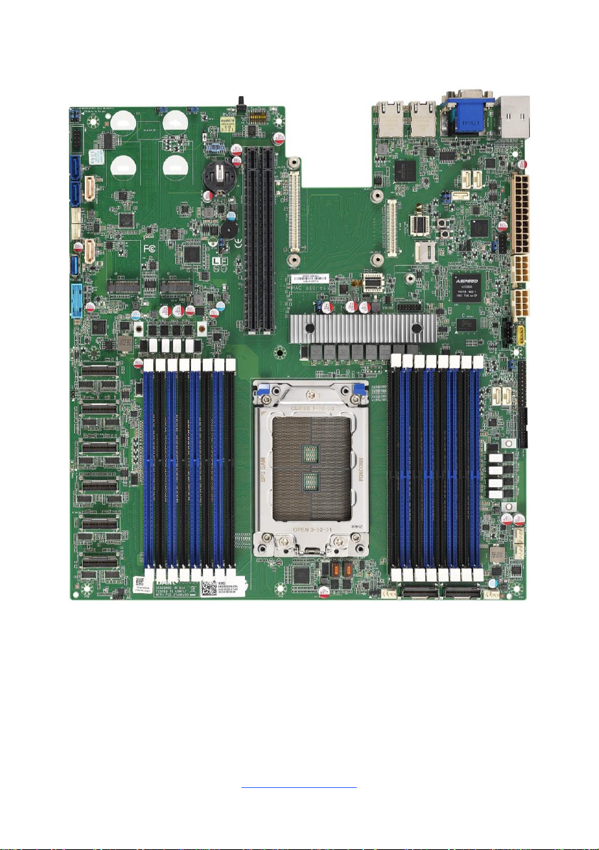
2.1 Board Image....................................................................................10
2.2 Block Diagram.................................................................................12
2.3 Motherboard Mechanical Drawing...................................................13
2.4Board Parts, Jumpers and Connectors...........................................14
2.5 LED Definitions................................................................................28
2.6Installing the Processor and Heatsink.............................................30
2.7Thermal Interface Material...............................................................35
2.8Tips on Installing Motherboard in Chassis ......................................36
2.9Installing the Memory ......................................................................38
2.10 Attaching Drive Cables..................................................................42
2.11 Installing Add-In Cards..................................................................43
2.12 Connecting External Devices ........................................................44
2.13 Installing the Power Supply...........................................................45
2.14 Finishing Up...................................................................................45
Chapter 3: BIOS Setup .............................................................................46
3.1 About the BIOS................................................................................46
3.2 Main Menu.......................................................................................48
3.3 Advanced Menu...............................................................................50
3.4 Chipset Menu ..................................................................................85
3.5AMD CBS Menu..............................................................................88
3.6 Server Management......................................................................104
3.7Security..........................................................................................109
3.8Boot ...............................................................................................114
3.9Save & Exit....................................................................................117
Chapter 4: Diagnostics...........................................................................119
4.1 Flash Utility....................................................................................119
4.2 AMIBIOS Post Code (Aptio)..........................................................120
Appendix I: Fan and Temp Sensors .....................................................127
Glossary...................................................................................................132
Technical Support ..................................................................................138

http://www.tyan.com
3
Before you begin…
Check the box contents!
The retail motherboard package should contain the following:
S8036 Motherboard x 1
SATA Single Cable x 2
Rear IO shielding x 3
1 x S8036 Quick Installation Guide
M.2 Screw kit x2
IMPORTANT NOTE:
Sales samples may not come with any of the accessories listed above.
If you have ordered a sales sample and you are missing any of the above items,
please contact your sales representative to help order accessories.

http://www.tyan.com
4
Chapter 1: Instruction
1.1 Congratulations
You have purchased the powerful TYAN® S8036 motherboard, based on the
Aspeed®AST2500 chipset. The S8036 is designed to support AMD®EPYC™ 7002
series Processor, and Up to 1,024GB RDIMM/ 4,096GB LRDIMM DDR4 2667 MHz
memory. Leveraging advanced technology from AMD®, the S8036 is capable of
offering scalable 32 and 64-bit computing, high-bandwidth memory design, and
lightning-fast PCI-E bus implementation.
The S8036 not only empowers you in today’s demanding IT environment but also
offers a smooth path for future application upgradeability. All of these rich feature
sets provide the S8036 with the power and flexibility to meet demanding
requirements for today’s IT environments.
Remember to visit the TYAN® website at http://www.tyan.com. There you can find
all the information on all TYAN®products as well as all the supporting documentation,
FAQs, Drivers and BIOS upgrades.
1.2 Hardware Specifications
S8036GM2NE Specifications
Processor
Q'ty / Socket Type
(1) AMD Socket SP3
Supported CPU Series
(1) AMD EPYC™ 7002 Series Processor
Thermal Design Power
(TDP) Wattage
Max up to 225W
Memory
Supported DIMM Qty
(16) DIMM slots
DIMM Type / Speed
DDR4 ECC RDIMM/RDIMM 3DS/LRDIMM/LRDIMM 3DS
3200
Capacity
Up to 1,024GB RDIMM/ 4,096GB LRDIMM
Memory channel
8 Channels per CPU
Memory voltage
1.2V
Expansion
Slots
PCI-E
(1) PCI-E Gen4 x 24 slot, (1) PCI-E Gen4 x 24 slot (w/x16
link; can be x24 link if OCP mezz. conn.B is not used.
Please contact with Tyan technical support for details.)
Recommended TYAN Riser
Card (PCI-E Gen3)
M7106-L24-3F, PCI-E x16 slot 2U riser card (left) ,M7106-
R24-3F, PCI-E x16 slot 2U riser card (right)
Recommended TYAN Riser
Card (PCI-E Gen4)
M8036-L24-3F, PCI-E x16 slot 2U riser card (left), M8036-
R24-3F, PCI-E x16 slot 2U riser card (right)

http://www.tyan.com
5
Others:
(1) PCI-E Gen3 x16 OCP 2.0 slot (conn.A+conn.B)
or (1) PCI-E Gen3 x8 OCP 2.0 slot (conn.A)
LAN
Q'ty / Port
(2) GbE ports + (1) dedicated for IPMI
Controller
Broadcom BCM5720
PHY
Realtek RTL8211E
Storage
SATA
Connector
(2) SFF-8654 for (16) SATA ports
Controller
Direct from AMD CPU
Speed
6Gb/s
RAID
N/A
Additional
SATA
Connector
(2) SATA-DOM,(2) SATA
Controller
Marvell 9235
Speed
6Gb/s
RAID
N/A
NVMe
Connector (M.2)
(2) 22110/2280 (by PCI-E Gen3 interface)
Connector (Slim
SAS)
(8) SFF-8654 for (16) NVMe ports
Graphic
Connector type
D-Sub 15-pin
Resolution
Up to 1920x1200
Chipset
Aspeed AST2500
Input
/Output
USB
(2) USB3.0 ports (at rear), (2) USB 2.0 ports (via
cable), (1) Type-A USB3.0 port
COM
(1) DB-9 COM Connector (at rear, COM1) + (1)
Header (COM2)
VGA
(1) D-Sub 15-pin VGA port (at rear)
RJ-45
(2) GbE ports, (1) Dedicated for IPMI
Front Panel
(1) 2x12-pin SSI front panel header
Power
SSI 24-pin + 8-pin + 8-pin power connectors
TPM
(Optional)
TPM Support
Please refer to our TPM supported list.
System
Monitoring
Chipset
Aspeed AST2500
Fan
Total (6) 4-pin headers
Temperature
Monitors temperature for CPU & memory & system
environment
Voltage
Monitors voltage for CPU, memory, chipset & power
supply
LED
Fan fail LED indicator, Over temperature warning
indicator, Fan & PSU fail LED indicator
Others
Watchdog timer support
Server
Management
AST2500 iKVM Feature
24-bit high quality video compression, Supports
storage over IP and remote platform-flash, USB 2.0

http://www.tyan.com
6
virtual hub
AST2500 IPMI Feature
IPMI 2.0 compliant baseboard management
controller (BMC), 10/100/1000 Mb/s MAC interface
BIOS
Brand / ROM size
AMI, 32MB
Feature
Hardware Monitor, SMBIOS 3.0/PnP/Wake on LAN,
Boot from USB device/PXE via LAN/Storage, Console
Redirection, ACPI 6.1, ACPI sleeping states S0, S5,
FAN speed control automatic
Physical
Dimension
Form Factor
EATX
Board Dimension
12" x 13" (305 x 330mm)
Regulation
FCC (SDoC)
Class A
CE (DoC)
Class A
Operating
Environment
Operating Temp.
10°C ~ 35°C (50°F~ 95°F)
Non-operating Temp.
- 40°C ~ 70°C (-40°F ~ 158°F)
In/Non-operating Humidity
90%, non-condensing at 35°C
RoHS
RoHS 6/6 Compliant
Yes
Operating
System
OS supported list
Please refer to our AVL support lists.
Package
Contains
Motherboard
(1) S8036 Motherboard
Manual
(1) Quick Installation Guide
I/O Shield
(1) I/O Shield
Cable (SATA)
(2) SATA signal cables
S8036GM2NE-LE Specifications
Processor
Q'ty / Socket Type
(1) AMD Socket SP3
Supported CPU Series
(1) AMD EPYC™ 7002 Series Processor
Thermal Design Power (TDP)
Wattage
Max up to 225W
Memory
Supported DIMM Qty
(16) DIMM slots
DIMM Type / Speed
DDR4 ECC RDIMM/RDIMM 3DS/LRDIMM/LRDIMM
3DS 3200
Capacity
Up to 1,024GB RDIMM/ 4,096GB LRDIMM
Memory channel
8 Channels per CPU

http://www.tyan.com
7
Memory voltage
1.2V
Expansion
Slots
PCI-E
(1) PCI-E Gen4 x 24 slot, (1) PCI-E Gen4 x 24 slot
(w/x16 link; can be x24 link if OCP mezz. conn.A is
not used. Please contact with Tyan technical support
for details.)
Recommended TYAN Riser
Card (PCI-E Gen3)
M7106-L24-3F, PCI-E x16 slot 2U riser card
(left) ,M7106-R24-3F, PCI-E x16 slot 2U riser card
(right)
Recommended TYAN Riser
Card (PCI-E Gen4)
M8036-L24-3F, PCI-E x16 slot 2U riser card (left),
M8036-R24-3F, PCI-E x16 slot 2U riser card (right)
Others:
(1) PCI-E Gen3 x16 OCP 2.0 slot (conn.A+conn.B) or
(1) PCI-E Gen3 x8 OCP 2.0 slot (conn.A)
LAN
Q'ty / Port
(2) GbE ports + (1) dedicated for IPMI
Controller
Broadcom BCM5720
PHY
Realtek RTL8211E
Storage
SATA
Connector
(2) SFF-8654 for (16) SATA ports
Controller
Direct from AMD CPU
Speed
6Gb/s
RAID
N/A
Additional
SATA
Connector
(2) SATA-DOM,(2) SATA
Controller
Marvell 9235
Speed
6Gb/s
RAID
N/A
NVMe
Connector (M.2)
(2) 22110/2280 (by PCI-E Gen3 interface)
Graphic
Connector type
D-Sub 15-pin
Resolution
Up to 1920x1200
Chipset
Aspeed AST2500
Input
/Output
USB
(2) USB3.0 ports (via cable), (2) USB3.0 ports (at
rear), (1) Type-A USB3.0 port
COM
(1) DB-9 COM Connector (at rear, COM1) +
(1) Header (COM2)
VGA
(1) D-Sub 15-pin VGA port (at rear)
RJ-45
(2) GbE ports, (1) Dedicated for IPMI
Front Panel
(1) 2x12-pin SSI front panel header
Power
SSI 24-pin + 8-pin + 8-pin power connectors
TPM
(Optional)
TPM Support
Please refer to our TPM supported list.
System
Monitoring
Chipset
Aspeed AST2500
Fan
Total (6) 4-pin headers
Temperature
Monitors temperature for CPU & memory & system

http://www.tyan.com
8
environment
Voltage
Monitors voltage for CPU, memory, chipset & power
supply
LED
Fan fail LED indicator, Over temperature warning
indicator, Fan & PSU fail LED indicator
Others
Watchdog timer support
Server
Management
AST2500 iKVM Feature
24-bit high quality video compression, Supports
storage over IP and remote platform-flash, USB 2.0
virtual hub
AST2500 IPMI Feature
IPMI 2.0 compliant baseboard management controller
(BMC), 10/100/1000 Mb/s MAC interface
BIOS
Brand / ROM size
AMI, 32MB
Feature
Hardware Monitor, SMBIOS 3.0/PnP/Wake on LAN,
Boot from USB device/PXE via LAN/Storage, Console
Redirection, ACPI 6.1, ACPI sleeping states S0, S5,
FAN speed control automatic
Physical
Dimension
Form Factor
EATX
Board Dimension
12" x 13" (305 x 330mm)
Regulation
FCC (SDoC)
Class A
CE (DoC)
Class A
Operating
Environment
Operating Temp.
10°C ~ 35°C (50°F~ 95°F)
Non-operating Temp.
- 40°C ~ 70°C (-40°F ~ 158°F)
In/Non-operating Humidity
90%, non-condensing at 35°C
RoHS
RoHS 6/6 Compliant
Yes
Operating
System
OS supported list
Please refer to our AVL support lists.
Package
Contains
Motherboard
(1) S8036 Motherboard
Manual
(1) Quick Installation Guide
I/O Shield
(1) I/O Shield
Cable (SATA)
(2) SATA signal cables
1.3 Software Specifications
For the latest AST2500 User’s Guide and OS (operation system) support, please
visit the Tyan’s Web site at http://www.tyan.com for the latest information

http://www.tyan.com
9
Chapter 2: Board Installation
You are now ready to install your motherboard.
How to install our products right… the first time
The first thing you should do is read this user’s manual. It contains important
information that will make configuration and setup much easier. Here are some
precautions you should take when installing your motherboard:
(1) Ground yourself properly before removing your motherboard from the
antistatic bag. Unplug the power from your computer power supply and
then touch a safely grounded object to release static charge (i.e. power
supply case). For the safest conditions, MiTAC recommends wearing a
static safety wrist strap.
(2) Hold the motherboard by its edges and do not touch the bottom of the
board, or flex the board in any way.
(3) Avoid touching the motherboard components, IC chips, connectors,
memory modules, and leads.
(4) Place the motherboard on a grounded antistatic surface or on the antistatic
bag that the board was shipped in.
(5) Inspect the board for damage.
The following pages include details on how to install your motherboard into your
chassis, as well as installing the processor, memory, disk drives and cables.
Caution!
1. To avoid damaging the motherboard and associated
components, do not use torque force greater than
5~7kgf/cm (4.35~6.09 lb/in) on each mounting screw
for motherboard installation.
2. Do not apply power to the board if it has been
damaged.

http://www.tyan.com
10
2.1 Board Image
S8036GM2NE

http://www.tyan.com
11
S8036GM2NE-LE
This picture is representative of the latest board revision available at the time of
publishing. The board you receive may not look exactly like the above picture.

http://www.tyan.com
12
2.2 Block Diagram
S8036 Block Diagram

http://www.tyan.com
13
2.3 Motherboard Mechanical Drawing

http://www.tyan.com
14
2.4 Board Parts, Jumpers and Connectors
This diagram is representative of the latest board revision available at the time of
publishing. The board you receive may not look exactly like the above diagram. The
DIMM slot numbers shown above can be used as a reference when reviewing the
DIMM population guidelines shown later in the manual. For the latest board revision,
please visit our web site at http://www.tyan.com.

http://www.tyan.com
15
Motherboard Components
Connectors
1. Dedicated IPMI port+USB3.0 x 2(LAN1)
24. PCIE 74P SlimSAS Connector (SLIMSAS 7
removed on -LE SKU)
2. CPU SMBUS Header (HDR_2)
25. PCIE 74P SlimSAS Connector (SLIMSAS 5
removed on -LE SKU)
3. CPU SMBUS Header (HDR_1)
26. PCIE 74P SlimSAS Connector (SLIMSAS 4
removed on -LE SKU)
4. VGA + COM Port (VGA_COM1)
27. PCIE 74P SlimSAS Connector (SLIMSAS 3
removed on -LE SKU)
5. CPU SMBUS Header (HDR_3)
28. Power SMBUS Header (PJ1)
6. BCM5720 RJ45 LAN Connector (LAN2)
29. CPU_FAN (CPU_FAN)
7. BCM5720 RJ45 LAN Connector (LAN3)
30. PCIE/SATA 74P SLIMSAS Connector
(SLIMSAS2)
8. TYAN Module Header (DBG_HD1)
31. PCIE/SATA 74P SLIMSAS Connector
(SLIMSAS1)
9. Rear ID LED Button (ID LED_BTN1)
32. Front Fan_3 (SYS_FAN_3)
10. HDT Header (HDT1)
33. Front Fan_2 (SYS_FAN_2)
11. COM2 Header (COM2)
34. Front Fan_1 (SYS_FAN_1)
12. SATA Connector (SATA 3.0 signals)
7Pin+2Power(SATADOM2)
35. CPU SMBUS Header (HDR_5)
13. SATA Connector (SATA4)
36. CPU SMBUS Header(HDR_4)
14. SATA Connector (SATA3)
37. FAN Header (FAN_HD1)
15. RearFan_2 (SYS_FAN_5)
38. Front Panel Header (FPIO_2)
16. RearFan_1 (SYS_FAN_4)
39. PSMI Header (PSMI_HD1)
17. SATA Connector(SATA 3.0 signals)
7Pin+2Power (SATADOM1)
40. IPMB Header (IPMB1)
18. Vertical Type A USB Connector
(TYPEA_USB1)
41. 8-pin Power Connector (PW3)
19. FPB USB2.0/USB3.0*2 Header
(USB3_FPIO1)
42. CPLD JTAG Connector (JTAG1)
20. NGFF 32x80mm & 32x110mm M.2
Connector (NGFF2)
43. 8-pin Power Connector (PW2)
21. NGFF 32x80mm & 32x110mm M.2
Connector (NGFF1)
44. ATX Power Connector (24p)(PW1)
22. PCIE 74P SlimSAS Connector
(SLIMSAS 8 removed on -LE SKU)
45. Power Button (PWR_BTN1)
23. PCIE 74P SlimSAS Connector
(SLIMSAS 6 removed on -LE SKU)
46. Reset Button (COLD_RST_BTN1)
Jumpers
a. J1 NVMe or SATA Select (J9_13)
e. BMC CPU COM1 (RX) (J197)
b. J1 NVMe or SATA Select (J9_24)
f. BMC COM PORT2 (TX) (J191)
c. CMOS Clear Jumper (J194)
g. BMC COM PORT2 (RX) (J190)
d. BMC CPU COM1 (TX) (J193)
h. PC BEEP (J120)
I. System RESET (J192)
PCIE Slots
A OCP B Slot (OCP1_B)
C. PCIE3.0 Slot x24 (PESLOT1)
B. OCP B Slot (OCP1_A)
D. PCIE3.0 Slot x24 (PESLOT2)

http://www.tyan.com
16
LEDs
iPSU_ALERT_N LED (PSMI_LED1)
vi BMC Heartbeat LED (BMC_HBLED)
ii PWR_GOOD_LED (LED5)
vii NGFF1_LED(LED_M1)
iii RESET_LED_LED (LED7)
viii NGFF2_LED(LED_M2)
iv P0_PROCHOT_ LED (LED4)
ix Onboard BMC IPMI ALERT LED (IPMI__LED2)
v Rear ID LED (ID_LED2)
x HDD_ACT_LED (HDD_LED3)
NOTE:
1. SD card socket is an OEM-reserved feature which is not enabled on current
product offering.
2. HDR_1-5: NVME Hotplug I2C connector for NVME HDD backplane.

http://www.tyan.com
17
HDR_1/HDR_2/HDR_3/HDR_4/HDR_5: CPU SMBUS Header
1
Signal
Pin
Pin
Signal
VDD_33_DUAL
1
2
HP_SCK
HP_SDA
3
4
HP_ALERT
NA
5
6
NA
GND
7
DBG_HD1: TYAN Module Header
Signal
Pin
Pin
Signal
VDD_33_RUN
1
2
FRAME_N
LAD0
3
4
KEY
LAD1
5
6
RESET#
LAD2
7
8
GND
LAD3
9
10
CLK
DBG_SERIRQ
11
12
GND
DBG_PRES_N
13
14
3VSB
NA
15
16
TPM_PP_EN
COM2: Serial Port Header
Signal
Pin
Pin
Signal
DCD
1
2
DSR
SIN
3
4
RTS
SOUT
5
6
CTS
DTR
7
8
RI
GND
9
10
KEY
CPU FAN/ SYS FAN1~5: 4-pin CPU Fan Connector
Pin
1
2
3
4
Signal
GND
VCC12
Sensor
Control
Use this header to connect the cooling fan to your motherboard to
keep the system stable and reliable.
Note: A 4-pin fan is required for fan support 4pin Control

http://www.tyan.com
18
SATADOM1/SATADOM2: SATA Connector
Name
TYPE
1
GND
2
SATA TX DP
3
SATA TX DN
4
GND
5
SATA RX DN
6
SATA RX DP
7
GND
P1
VCC(P5V)
P2
GND
Connects to the Serial ATA ready drives via the Serial ATA cable.
SATA_3/SATA_4: 7-pin SATA 3.0 Connector
Name
TYPE
1
GND
2
SATA TX DP
3
SATA TX DN
4
GND
5
SATA RX DN
6
SATA RX DP
7
GND
TYPEA_USB1: Vertical (Type_A) USB3.0 Connector
Signal
Pin
Pin
Signal
+5V
1
2
USB2.0_DATA_N
USB2.0_DATA_P
3
4
GND
USB3.0_RX_N
5
6
USB3.0_RX_P
GND
7
8
USB3.0_TX_N
USB3.0_TX_P
9
USB3_FPIO1: Front USB3.0 Header
Signal
Pin
Pin
Signal
USB3_VCC_FP
1
2
P0_RXN
P0_RXP
3
4
GND
P0_TXN
5
6
P0_TXP
GND
7
8
P0_N
P0_P
9
10
OC_N
P1_P
11
12
P1_N
GND
13
14
P1_TX_P
P1_TX_N
15
16
GND
P1_RX_P
17
18
P1_RX_N
USB3_VCC_FP
19
20
NA

http://www.tyan.com
19
ID LED_BTN1: Rear IO IDLED Button
Signal
Pin
Pin
Signal
FP_IDLED_BTN_N
1
2
GND
IPMB_HD1: IPMB Connector
Signal
Pin
Pin
Signal
BMC_SMB_DATA
1
2
GND
BMC_SMB_CLK
3
4
NC
PSMI_HD1: PSMI Connector
Pin
1
2
3
4
5
Signal
SMB_CLK
SMB_DAT
SMB_ALERT#
GND
V3P3
FAN_HD1: System FAN Connector
Signal
Pin
Pin
Signal
TACH1
1
2
TACH6
TACH2
3
4
TACH7
TACH3
5
6
TACH8
TACH4
7
8
TACH9
TACH5
9
10
TACH10
GND
11
12
KEY
PWM2
13
14
PWM1
TACH11
15
16
SMB_DATA
TACH12
17
18
SMB_CLK
NC
19
20
PWM3
FPIO2: Front Panel Connector
Signal
Pin
Pin
Signal
PWRLED+
1
2
V3P3_AUX
KEY
3
4
IDLED+
PWRLED-
5
6
IDLED-
HDDLED+
7
8
SYS_FAULT1-
HDDLED-
9
10
SYS_FAULT2-
PWR_SW#
11
12
LAN0LED+
GND
13
14
LAN0LED-
RESET_SW#
15
16
SMBDATA
GND
17
18
SMBCLK
IDLED_SW#
19
20
INTRUSION#
SYS_Air_Inlet
21
22
LAN1LED+
NMI_SW#
23
24
LAN1LED-

http://www.tyan.com
20
PWR_BTN1: POWER Button
Pin
1
2
3
4
Signal
GND
GND
PWR_BTN1
PWR_BTN1
RST_BTN1: COLD Reset Button
Pin
1
2
3
4
Signal
GND
GND
FP_RST_BTN_N
FP_RST_BTN_N
PJ1: SMBus Connector
Signal
Pin
Pin
Signal
SMB CLK
1
2
SMB DATA
GND
3
J9: J1 NVMe or SATA Select Jumper
Signal
Pin
Pin
Signal
VDD_33_RUN
1
2
VDD_33_RUN
J1_SATA_NVME#
3
4
J2_SATA_NVME#
GND
5
6
GND
1-3: J1 (SlimSAS1) NVME SMBUS
3-5: J1 (SlimSAS1) SATA SGPIO
J9: J2 NVMe or SATA Select Jumper
Signal
Pin
Pin
Signal
VDD_33_RUN
1
2
VDD_33_RUN
J1_SATA_NVME#
3
4
J2_SATA_NVME#
GND
5
6
GND
2-4: J2 (SlimSAS2) NVME SMBUS
4-6: J2 (SlimSAS2) SATA SGPIO
J190/J191: BMC COM PORT2 (RX/TX) Jumper
Signal
Pin
Pin
Signal
BMC_COM_TXD/
BMC_COM_RXD
1
2
TXD_OUT/RXD_OUT
BMC_TXD5
BMC_RXD5
3
1-2 : BMC COM PORT2 (DEFAULT)
2-3 : BMC CONSOLE PORT5
Table of contents
Other TYAN Motherboard manuals

TYAN
TYAN S2692 User manual

TYAN
TYAN THUNDER 2500 User manual

TYAN
TYAN TRINITY 400 User manual

TYAN
TYAN TOLEDO I3000R User manual

TYAN
TYAN THUNDER K8SRE User manual

TYAN
TYAN THUNDER N6650W User manual

TYAN
TYAN S5510 User manual

TYAN
TYAN TEMPEST II User manual

TYAN
TYAN Thunder n3600QX User manual

TYAN
TYAN Triumph i7230 User manual