TYAN S8050 User manual

http://www.tyan.com
1
S8050
Version 1.0c
Copyright
Copyright © 2022 MiTAC International Corporation. All rights reserved. No part of
this manual may be reproduced or translated without prior written consent from
MiTAC International Corporation.
Trademark
All registered and unregistered trademarks and company names contained in this
manual are property of their respective owners including, but not limited to the
following.
TYAN®is a trademark of MiTAC International Corporation.
AMD®is a trademark of AMD®Corporation.
AMI, AMI BIOS are trademarks of AMI Technologies.
Microsoft®, Windows®are trademarks of Microsoft Corporation.
Winbond®is a trademark of Winbond Electronics Corporation.
Notice
Information contained in this document is furnished by MiTAC International
Corporation and has been reviewed for accuracy and reliability prior to printing.
MiTAC assumes no liability whatsoever, and disclaims any express or implied
warranty, relating to sale and/or use of TYAN®products including liability or
warranties relating to fitness for a particular purpose or merchantability. MiTAC
retains the right to make changes to product descriptions and/or specifications at
any time, without notice. In no event will MiTAC be held liable for any direct or
indirect, incidental or consequential damage, loss of use, loss of data or other
malady resulting from errors or inaccuracies of information contained in this
document.

http://www.tyan.com
2
Contents
S8050............................................................................................................ 1
Before you begin….................................................................................... 3
Chapter 1: Instruction ................................................................................ 4
1.1 Congratulations ................................................................................. 4
1.2 Hardware Specifications.................................................................... 4
1.3 Software Specifications ..................................................................... 8
Chapter 2: Board Installation..................................................................... 9
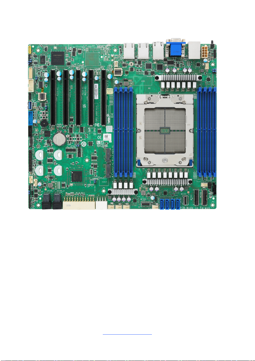
2.1 Board Image .................................................................................... 10
2.2 Block Diagram ................................................................................. 11
2.3 Motherboard Mechanical Drawing................................................... 12
2.4 Board Parts, Jumpers and Connectors ........................................... 13
2.5 LED Definitions................................................................................ 23
2.6 Installing the Processor and Heatsink ............................................. 26
2.7 Thermal Interface Material .............................................................. 30
2.8 Tips on Installing Motherboard in Chassis ...................................... 31
2.9 Installing the Memory ...................................................................... 33
2.10 Installing Add-In Cards .................................................................. 37
2.11 Connecting External Devices ........................................................ 38
2.12 Installing the Power Supply ........................................................... 39
2.13 Finishing Up................................................................................... 40
Chapter 3: BIOS Setup ............................................................................. 41
3.1 About the BIOS................................................................................ 41
3.2 Main Menu....................................................................................... 43
3.3 Advanced Menu............................................................................... 45
3.4 CPU Configuration........................................................................... 97
3.5 Chipset Menu ................................................................................ 100
3.6 Server Management ...................................................................... 131
3.7 Security.......................................................................................... 140
3.8 Boot ............................................................................................... 145
3.9 Save & Exit .................................................................................... 149
Chapter 4: Diagnostics........................................................................... 151
4.1 Flash Utility .................................................................................... 151
4.2 AMIBIOS Post Code (Aptio) .......................................................... 152
Appendix I: Fan and Temp Sensors ..................................................... 159
Appendix II: How to recover UEFI BIOS ............................................... 163
Glossary................................................................................................... 165
Technical Support .................................................................................. 171

http://www.tyan.com
3
Before you begin…
Check the box contents!
The retail motherboard package should contain the following:
S8050 Motherboard x 1
SATA Cable x 2
M.2 Latch x 2
Rear IO shielding x 1
1 x S8050 Quick Installation Guide
IMPORTANT NOTE:
Sales samples may not come with any of the accessories listed above.
If you have ordered a sales sample and you are missing any of the above items,
please contact your sales representative to help order accessories.

http://www.tyan.com
4
Chapter 1: Instruction
1.1 Congratulations
You have purchased the powerful TYAN® S8050 motherboard, based on the
Aspeed®AST2600 chipset. The S8050 is designed to support AMD®EPYC™ 9004
Series Processor, and up to 2,048GB RDIMM / 3DS RDIMM DDR5 4800 memory.
Leveraging advanced technology from AMD®, the S8050 is capable of offering
scalable 32 and 64-bit computing, high-bandwidth memory design, and lightning-
fast PCI-E bus implementation.
The S8050 not only empowers you in today’s demanding IT environment but also
offers a smooth path for future application upgradeability. All of these rich feature
sets provide the S8050 with the power and flexibility to meet demanding
requirements for today’s IT environments.
Remember to visit the TYAN® website at http://www.tyan.com. There you can find
all the information on all TYAN®products as well as all the supporting documentation,
FAQs, Drivers and BIOS upgrades.
1.2 Hardware Specifications
S8050GM2NE Specifications
Processor
Q'ty / Socket Type (1) AMD Socket SP5
Supported CPU Series (1) AMD EPYC™ 9004 Series Processor
Thermal Design Power
Wattage
Max up to 400W (cTDP)
Memory
Supported DIMM Qty (8) DIMM slots
DIMM Type / Speed RDDR5 4800 w/ ECC (1.1V) when 1DPC
3DS RDDR5 4800 w/ ECC (1.1V) when 1DPC
Capacity Up to 2,048GB RDIMM / 3DS RDIMM DDR5 4800
Memory channel 8 Channels per CPU
Memory voltage 1.1V
Expansion Slots PCIe (5) PCIe Gen.5 x16 slot
LAN
Q'ty / Port (2) GbE ports + (1) GbE dedicated for IPMI
Controller Intel I210-AT
PHY Realtek RTL8211F
Storage SATA
Connector (12) SATA
Controller Direct from AMD EPYC CPU
Speed 6Gb/s
RAID N/A

http://www.tyan.com
5
Storage NVMe Connector (M.2) (2) 22110/2280 (by PCIe Gen.4 interface)
Connector (U.2) (2) MCIO x4 / (2) MCIO x8
Graphic VGA
Connector type D-Sub 15-pin
Resolution Up to 1920X1080 @60Hz
Chipset Aspeed AST2600
Input /Output
NVMe (2) MCIO x4 / (2) MCIO x8
USB (2) USB3.2 Gen.1 ports (@ front) /
(1) USB3.2 Gen.1 conn ( Type-A ) /
(2) USB3.2 Gen.1 ports (@ rear)
COM (1) DB-9 COM Connector
VGA (1) D-Sub 15-pin port
RJ-45 (2) GbE ports + (1) GbE dedicated for IPMI
Front Panel (1) 2x12-pin SSI front panel header
SATA (2) Mini-SAS HD (SFF-8643) connectors /
(4) 7-pin SATA connectors
Power (2) 2x4 Power input connectors /
(1) 2x12 Power input connectors
Others (1) ID button
TPM (Optional) TPM Support Please refer to our TPM supported list.
Interface SPI
System
Monitoring
Chipset Aspeed AST2600
Fan Total (6) 4-pin headers
Temperature Monitors temperature for CPU & system
environment
Voltage Monitors voltage for CPU, memory, chipset & power
supply
LED Fan fail LED indicator / Over temperature warning
indicator
Others Watchdog timer support
Server
Management
Onboard Chipset Onboard Aspeed AST2600
AST2600 iKVM Feature 24-bit high quality video compression / Supports
storage over IP and remote platform-flash / USB 2.0
virtual hub
AST2600 IPMI Feature IPMI 2.0 compliant baseboard management
controller (BMC) / 10/100/1000 Mb/s MAC interface
BIOS
Brand / ROM size AMI / 256MB
Feature Hardware Monitor / FAN speed control automatic /
Boot from USB device/PXE via LAN/Storage /
Console Redirection / SMBIOS 3.0/PnP/Wake on LAN
/ ACPI sleeping states S0, S5
Physical
Dimension
Form Factor CEB
Board Dimension 12” x 10.5” (305 x 267mm)

http://www.tyan.com
6
Regulation
FCC (SDoC) Class A
CE (DoC) Class A
C-Tick Class A
VCCI Class A
Operating
Environment
Operating Temp. 10° C ~ 35° C (50° F~ 95° F)
Non-operating Temp. - 40° C ~ 70° C (-40° F ~ 158° F)
In/Non-operating
Humidity
90%, non-condensing at 35° C
RoHS RoHS 6/6 Compliant Yes
Operating
System
OS supported list Please refer to our AVL support lists.
Package
Contains
Motherboard (1) S8050 Motherboard
Manual (1) Quick Installation Guide
I/O Shield (1) I/O Shield
Cable SATA (2) SATA signal cables

http://www.tyan.com
7
S8050GM4NE-2T Specifications
Processor
Q'ty / Socket Type (1) AMD Socket SP5
Supported CPU Series (1) AMD EPYC™ 9004 Series Processor
Thermal Design Power
Wattage
Max up to 400W (cTDP)
Memory
Supported DIMM Qty (8) DIMM slots
DIMM Type / Speed RDDR5 4800 w/ ECC (1.1V) when 1DPC
3DS RDDR5 4800 w/ ECC (1.1V) when 1DPC
Capacity Up to 2,048GB RDIMM / 3DS RDIMM DDR5 4800
Memory channel 8 Channels per CPU
Memory voltage 1.1V
Expansion Slots PCIe (5) PCIe Gen.5 x16 slot
LAN
Q'ty / Port (2) 10GbE ports + (2) GbE ports +
(1) GbE dedicated for IPMI
Controller Intel I210-AT / Intel X710-AT2
PHY Realtek RTL8211F
Storage SATA
Connector (12) SATA
Controller Direct from AMD EPYC CPU
Speed 6Gb/s
RAID N/A
Storage NVMe Connector (M.2) (2) 22110/2280 (by PCIe Gen.4 interface)
Connector (U.2) (2) MCIO x4 / (2) MCIO x8
Graphic VGA
Connector type D-Sub 15-pin
Resolution Up to 1920X1080 @60Hz
Chipset Aspeed AST2600
Input /Output
NVMe (2) MCIO x4 / (2) MCIO x8
USB (2) USB3.2 Gen.1 ports (@ front) /
(1) USB3.2 Gen.1 conn ( Type-A ) /
(2) USB3.2 Gen.1 ports (@ rear)
COM (1) DB-9 COM Connector
VGA (1) D-Sub 15-pin port
RJ-45 (2) 10GbE ports + (2) GbE ports +
(1) GbE dedicated for IPMI
Front Panel (1) 2x12-pin SSI front panel header
SATA (2) Mini-SAS HD (SFF-8643) connectors /
(4) 7-pin SATA connectors
Power (2) 2x4 Power input connectors /
(1) 2x12 Power input connectors
Others (1) ID button
TPM (Optional) TPM Support Please refer to our TPM supported list.
Interface SPI

http://www.tyan.com
8
System
Monitoring
Chipset Aspeed AST2600
Fan Total (6) 4-pin headers
Temperature Monitors temperature for CPU & system
environment
Voltage Monitors voltage for CPU, memory, chipset & power
supply
LED Fan fail LED indicator / Over temperature warning
indicator
Others Watchdog timer support
Server
Management
Onboard Chipset Onboard Aspeed AST2600
AST2600 iKVM Feature 24-bit high quality video compression / Supports
storage over IP and remote platform-flash / USB 2.0
virtual hub
AST2600 IPMI Feature IPMI 2.0 compliant baseboard management
controller (BMC) / 10/100/1000 Mb/s MAC interface
BIOS
Brand / ROM size AMI / 256MB
Feature Hardware Monitor / FAN speed control automatic /
Boot from USB device/PXE via LAN/Storage /
Console Redirection / SMBIOS 3.0/PnP/Wake on LAN
/ ACPI sleeping states S0, S5
Physical
Dimension
Form Factor CEB
Board Dimension 12” x 10.5” (305 x 267mm)
Regulation
FCC (SDoC) Class A
CE (DoC) Class A
C-Tick Class A
VCCI Class A
Operating
Environment
Operating Temp. 10° C ~ 35° C (50° F~ 95° F)
Non-operating Temp. - 40° C ~ 70° C (-40° F ~ 158° F)
In/Non-operating
Humidity
90%, non-condensing at 35° C
RoHS RoHS 6/6 Compliant Yes
Operating
System
OS supported list Please refer to our AVL support lists.
Package
Contains
Motherboard (1) S8050 Motherboard
Manual (1) Quick Installation Guide
I/O Shield (1) I/O Shield
Cable SATA (2) SATA signal cables
1.3 Software Specifications
For the latest AST2600 User’s Guide and OS (operation system) support, please
visit the Tyan’s Web site at http://www.tyan.com for the latest information

http://www.tyan.com
9
Chapter 2: Board Installation
You are now ready to install your motherboard.
How to install our products right… the first time
The first thing you should do is read this user’s manual. It contains important
information that will make configuration and setup much easier. Here are some
precautions you should take when installing your motherboard:
(1) Ground yourself properly before removing your motherboard from the
antistatic bag. Unplug the power from your computer power supply and
then touch a safely grounded object to release static charge (i.e. power
supply case). For the safest conditions, MiTAC recommends wearing a
static safety wrist strap.
(2) Hold the motherboard by its edges and do not touch the bottom of the
board, or flex the board in any way.
(3) Avoid touching the motherboard components, IC chips, connectors,
memory modules, and leads.
(4) Place the motherboard on a grounded antistatic surface or on the antistatic
bag that the board was shipped in.
(5) Inspect the board for damage.
The following pages include details on how to install your motherboard into your
chassis, as well as installing the processor, memory, disk drives and cables.
Caution!
1. To avoid damaging the motherboard and associated
components, do not use torque force greater than
5~7kgf/cm (4.35~6.09 lb/in) on each mounting screw
for motherboard installation.
2. Do not apply power to the board if it has been
damaged.

http://www.tyan.com
10
2.1 Board Image
S8050GM2NE-2T
This picture is representative of the latest board revision available at the time of
publishing. The board you receive may not look exactly like the above picture.

http://www.tyan.com
11
2.2 Block Diagram
S8050 Block Diagram

http://www.tyan.com
12
2.3 Motherboard Mechanical Drawing

http://www.tyan.com
13
2.4 Board Parts, Jumpers and Connectors
This diagram is representative of the latest board revision available at the time of
publishing. The board you receive may not look exactly like the above diagram. The
DIMM slot numbers shown above can be used as a reference when reviewing the
DIMM population guidelines shown later in the manual. For the latest board
revision, please visit our web site at http://www.tyan.com.

http://www.tyan.com
14
Jumpers & Connectors
Connectors
1. IPMB Connector (IPMB1) 26. 4-pin Fan Connector (SYS_FAN_2)
2. Front Fan Header(FAN_HD1) 27. M.2 Connector (CN1) PCIE only
3. COM2 Port Header(COM2) 28. MCIOx4 SATA/NVME (CN10)
4. TYAN Module Header(J62) 29. 4-pin Fan Connector (SYS_FAN_1)
5. TYPE A USB3.2 Gen1
Header(TYPEA_USB1) 30. 7p SATA Connector (J15)
6. NMI Button (SW5) 31. 7p SATA Connector (J16)
7. USB3.2 Gen1 Header (USB3_FPIO1) 32. 7p SATA Connector (J18)
8. COLD RST Button (SW2) 33. 7p SATA Connector (J19)
9. SGPIO0 Header (SGPIO0) 34. MCIOx4 SATA/NVME (CN11)
10. PWR Button (SW1) 35. MCIOx8 NVME (CN6)
11. HDT Header(J1) 36. MCIOx8 NVME (CN5)
12. WARM_RST Button (SW12) 37. PSMI Header (PSMI_HD1)
13. I210 LAN LED Header (J29) 38. SVI Header (J17)
14. Front Panel Header (FPIO_2) 39. 4-pin Fan Connector (CPU0_FAN)
15. HDD BP Smbus Header(HDR_2) 40. 4-pin Fan Connector (SYS_FAN_5)
16. HDD BP Smbus Header(HDR_1) 41. VGA Header (VGA1)
17. Intrusion Header(J66) 42. ID Button (ID_BTN)
18. CPLD JTAG Header (J12) 43. CPU and Memory Power Connector
(PW3)
19. M.2 Connector (CN3)PCIE Only 44. IPMI LAN USB3.0 Connector (LAN5)
20. Mini SAS Connector (J26) 45. VGA and COM1 Port Header
(VGA_COM1)
21. Mini SAS Connector (J25) 46. RJ45 LAN Port (LAN3/LAN4)
22. Power Connector (PW1) 47. RJ45 LAN Port (LAN1)
23. CPU and Memory Power Connector (PW2) 48. RJ45 LAN Port (LAN2)
24. 4-pin Fan Connector (SYS_FAN_4) 49. BIOS Debug (BIOS_DBG1)
25. 4-pin Fan Connector (SYS_FAN_3) 50. SPI TPM Connector (J56)
Slots
A. PCIE#3 x16 (PESLOT3) D. PCIE#2 x16 (PESLOT2)
B. PCIE#5 x16 (PESLOT5) E. PCIE#1 x16 (PESLOT1)
C. PCIE#4 x16 (PESLOT4)
Jumpers
a. COM2 Switch Jumper(J6) f. BMC Header (J2)
b. COM2 Switch Jumper (J7) g. CPLD PowerOn Jumper (J3)
c. RESET Switch Jumper (J33) h. VRM SMBUS SEL Jumper (3PHD1)

http://www.tyan.com
15
d. NCSI Switch Jumper (J4) i. COM1 Switch Jumper (J9)
e. CLEAR CMOS Jumper (J75) j. COM1 Switch Jumper (J8)
LEDS
I PROCHOT LED VI PWROK LED
II BMC heartbeat LED VII BMC ALERT LED
III CPU RESET LED VIII SYS_PWROK LED
IV SATA & M.2 LED IX PSU_ALERT LED
VPWR_GOOD LED
Jumper Legend
OPEN - Jumper OFF Without jumper cover
CLOSED - Jumper ON With jumper cover

http://www.tyan.com
16
CPU0_FAN, SYS_FAN_1~5: 4-pin FAN Connector
Pin 1 2 3 4
Signal GND P12V FAN_TACH FAN_PWM
Use this header to connect the cooling fan to your motherboard to
keep the system stable and reliable.
FPIO_2: Front Panel Connector
Signal Pin Pin Signal
PWRLED+ 1 2 VDD_33_DUAL
KEY 3 4 IDLED+
PWRLED- 5 6 IDLED-
HDDLED+ 7 8 SYS_FAULT1-
HDDLED- 9 10 SYS_FAULT2-
PWR_SW# 11 12 LAN1LED+
GND 13 14 LAN1LED-
RESET_SW# 15 16 SMBDATA
GND 17 18 SMBCLK
IDLED_SW# 19 20 INTRUSION#
NC 21 22 LAN2LED+
NMI_SW# 23 24 LAN2LED-
PSMI_HD1: PSMI Header
Pin Signal
1 SMB_CLK
2 SMB_DAT
3 PSU_SMBALERT_N
4 GND
5 V3.3
IPMB_HD1: 4-pin IPMB Connector
Pin Signal
1 IPMB_DAT
2 GND
3 IPMB_CLK
4 VCC3_AUX

http://www.tyan.com
17
J62: TYAN Module Header
Signal Pin Pin Signal
VDD_33_DUAL 1 2 ESPI_CS1
IO0 3 4 KEY
IO1 5 6 RESET#
IO2 7 8 GND
IO3 9 10 CLK
ALERT 11 12 GND
FAN_HD1: Front Fan Connector (Reserved for Barebone)
Signal Pin Pin Signal
TACH1 1 2 TACH6
TACH2 3 4 TACH7
TACH3 5 6 TACH8
TACH4 7 8 TACH9
TACH5 9 10 TACH10
GND 11 12 GND
PWM3 13 14 PWM2
TACH11 15 16 SDA
TACH12 17 18 SCL
GND 19 20 PWM4
GND 21 22 GND
TACH13 23 24 TACH15
TACH14 25 26 TACH16
PWM5 27 28 PWM7
PWM0 29 30 GND
USB3_FPIO1: USB3.2 Gen1 Header
Signal Pin Pin Signal
+5V 1 20 KEY
P0_RX_N 2 19 +5V
P0_RX_P 3 18 P1_RX_N
GND 4 17 P1_RX_P
P0_TX_N 5 16 GND
P0_TX_P 6 15 P1_TX_N
GND 7 14 P1_TX_P
P0_N 8 13 GND
P0_P 9 12 P1_N
OC_N 10 11 P1_P

http://www.tyan.com
18
SSATA_SGPIO0: SATA SGPIO Pin Header for SSATA0
Signal Pin Pin Signal
SCL 1 2 NC
SDA 3 4 SDATA OUT-
GND 5 6 SLOAD
KEY 7 8 SCLOCK
VCC3_AUX 9 10 NC
VGA1: Front Panel VGA Header
Signal Pin Pin Signal
GND 1 2 VGA2_5V
GND 3 4 HD_VGA_R
GND 5 6 HD_VGA_G
GND 7 8 HD_VGA_B
GND 9 10 HD_VGA_DAT
HD_VGA_HS 11 12 KEY
HD_VGA_CLK 13 14 HD_VGA_VS
COM2: COM Port Header
Signal Pin Pin Signal
COM2_DCD 1 2 COM2_DSR
COM2_RXD 3 4 COM2_RTS
COM2_TXD 5 6 COM2_CTS
COM2_DTR 7 8 COM2_NRI
GND 9 10 KEY
HDR_1/2: HDD BP Smbus Header
Signal Pin Pin Signal
VCC3_AUX 1 2 HP0_SCK
HP0_SDA 3 4 CPU01_SMBALERT_N_C
NC 5 6 NC
GND 7
TYPEA_USB1: Vertical Type-A USB3.2 Gen1 Connector
Signal Pin Pin Signal
USB3_N3_RX_TYPEA 5 1 VCC5
USB3_P3_RX_TYPEA 6 2 USB2_N8_TYPE_A_R
GND 7 3 USB2_P8_TYPE_A_R
USB3_N3_TX_TYPEA 8 4 GND
USB3_P3_TX_TYPEA 9

http://www.tyan.com
19
IDLED_BTN1: Rear IO ID LED Button
Signal Pin Pin Signal
FP_IDLED_BTN_N 1 2 GND
PWR_BTN1: System Power Button
Signal Pin Pin Signal
GND 1,2 3,4 PWR_BTN1
RST_BTN1: COLD Reset Button
Signal Pin Pin Signal
GND 1,2 3,4 FP_RST_BTN_N
BIOS_DBG1: BIOS Debug Header
Signal Pin Pin Signal
SPI_CS# 1 2 VDD_33_DUAL
SPI_DO 3 4 SPI_HOLD#
SPI_WP# 5 6 SPI_CLK
GND 7 8 SPI_DI
J66: Intrusion Header
Pin Signal
1 SCM_CHASSIS_INTR_L
2 GND
J1: HDT Header
Signal Pin Pin Signal
P1V8_AUX 1 2 TCK
GND 3 4 TMS
GND 5 6 TDI
GND 7 8 TDO
TRST_N 9 10 PEROK
NC 11 12 RESET_N
NC 13 14 NC
NC 15 16 DBREQ_N
GND 17 18 NC
P1V8_AUX 19 20 NC

http://www.tyan.com
20
CN1/CN2: M.2 Connector
Signal Pin Pin Signal
GND 1 2 VCC3
GND 3 4 VCC3
NC 5 6 NC
NC 7 8 VCC3_AUX
GND 9 0 M2_LED_N
NC 11 12 VCC3
NC 13 14 VCC3
GND 15 16 VCC3
NC 17 18 VCC3
NC 19 20 NC
GND 21 22 NC
NC 23 24 NC
NC 25 26 NC
GND 27 28 NC
PCH_PE1_M2_1_RX_N 29 30 NC
PCH_PE1_M2_1_RX_P 31 32 NC
GND 33 34 NC
PCH_PE1_M2_1_TX_N 35 36 NC
PCH_PE1_M2_1_TX_P 37 38 NC
GND 39 40 M2_SMB_CLK_R
PCH_PE0_M2_0_RX_N 41 42 M2_SMB_DAT_R
PCH_PE0_M2_0_RX_P 43 44 NC
GND 45 46 NC
PCH_PE0_M2_0_TX_N 47 48 NC
PCH_PE0_M2_0_TX_P 49 50 M2_PERST_N_R
GND 51 52 NC
CLK_100M_M2_DN 53 54 M2_2_PEWAKE_N
CLK_100M_M2_DP 55 56 NC
GND 57 58 NC
PE_M.2_DETECT_N 67 68 NC
NC 69 70 VCC3
GND 71 72 VCC3
GND 73 74 VCC3
GND 75 76 GND
GND 77
Table of contents
Other TYAN Motherboard manuals

TYAN
TYAN TRINITY KT400 User manual

TYAN
TYAN InterServe 90 User manual

TYAN
TYAN TRINITY 100AT User manual

TYAN
TYAN S7056 User manual

TYAN
TYAN TOMCAT I845GV User manual

TYAN
TYAN TIGER I7501R User manual

TYAN
TYAN THUNDER K8SRE User manual

TYAN
TYAN S8212 User manual

TYAN
TYAN Tiger 100 S1832DL User manual

TYAN
TYAN TOMCAT I7230A User manual

TYAN
TYAN S5501 Operation and maintenance manual

TYAN
TYAN TRINITY 450 User manual

TYAN
TYAN Tempest i5100T User manual

TYAN
TYAN TIGER GC-SL User manual

TYAN
TYAN Toledo q35T User manual

TYAN
TYAN TIGER 100 User manual

TYAN
TYAN S5530 User manual

TYAN
TYAN THUNDER LE User manual

TYAN
TYAN Tomcat i7221 S5150 User manual

TYAN
TYAN TIGER 133 User manual