TYAN THUNDER K8WE User manual

http://www.tyan.com
1
Thunder K8WE /// S2895
Version 1.01
Copyright
Copyright © TYAN Computer Corporation, 2004-2005. All rights reserved. No
part of this manual may be reproduced or translated without prior written
consent from TYAN Computer Corp.
Trademark
All registered and unregistered trademarks and company names contained in
this manual are property of their respective owners including, but not limited to
the following.
TYAN, Taro and Thunder K8WE are trademarks of TYAN Computer
Corporation.
AMD, Opteron, and combinations thereof are trademarks of AMD Corporation.
Microsoft, Windows are trademarks of Microsoft Corporation.
SuSE,is a trademark of SuSE AG.
Linux is a trademark of Linus Torvalds
IBM, PC, AT, and PS/2 are trademarks of IBM Corporation.
Winbond is a trademark of Winbond Electronics Corporation.
Notice
Information contained in this document is furnished by TYAN Computer
Corporation and has been reviewed for accuracy and reliability prior to printing.
TYAN assumes no liability whatsoever, and disclaims any express or implied
warranty, relating to sale and/or use of TYAN products including liability or
warranties relating to fitness for a particular purpose or merchantability. TYAN
retains the right to make changes to product descriptions and/or specifications
at any time, without notice. In no event will TYAN be held liable for any direct or
indirect, incidental or consequential damage, loss of use, loss of data or other
malady resulting from errors or inaccuracies of information contained in this
document.

http://www.tyan.com
2
Table of Contents
Chapter 1: Introduction
1.1 Congratulations Page 3
1.2 Hardware Specifications Page 3
1.3 Software Specifications Page 5
Chapter 2: Board Installation
2.1 Board Image Page 8
2.2Block Diagram Page 9
2.3Board Parts, Jumpers and Connectors Page 10
2.4Installing the Processor(s) Page 18
2.5Heatsink Retention Frame Installation Page 19
2.6Thermal Interface Material Page 20
2.7Heatsink Installation Procedures Page 21
2.8Finishing Installing the Heatsink Page 23
2.9Tips on Installing Motherboard in Chassis Page 24
2.10 Installing the Memory Page 25
2.11 Attaching Drive Cables Page 28
2.12 Installing Add-In Cards Page 30
2.13 Connecting External Devices Page 31
2.14 Installing the Power Supply Page 32
2.15 Finishing Up Page 33
Chapter 3: BIOS
3.1 BIOS Setup Utility Page 35
3.2BIOS Menu Bar Page 36
3.3BIOS Legend Bar Page 36
3.4 Getting Help Page 36
3.5BIOS Main Menu Page 37
3.6BIOS Advanced Menu Page 38
3.7BIOS Memory Menu Page 52
3.8BIOS Boot Menu Page 54
3.9BIOS Exit Menu Page 56
Chapter 4: Diagnostics
4.1 Beep Codes Page 57
4.2 Flash Utility Page 57
4.3 BIOS Post Code Page 58
Glossary Page 61
Technical Support Page 67

http://www.tyan.com
3
Chapter 1: Introduction
1.1 -Congratulations
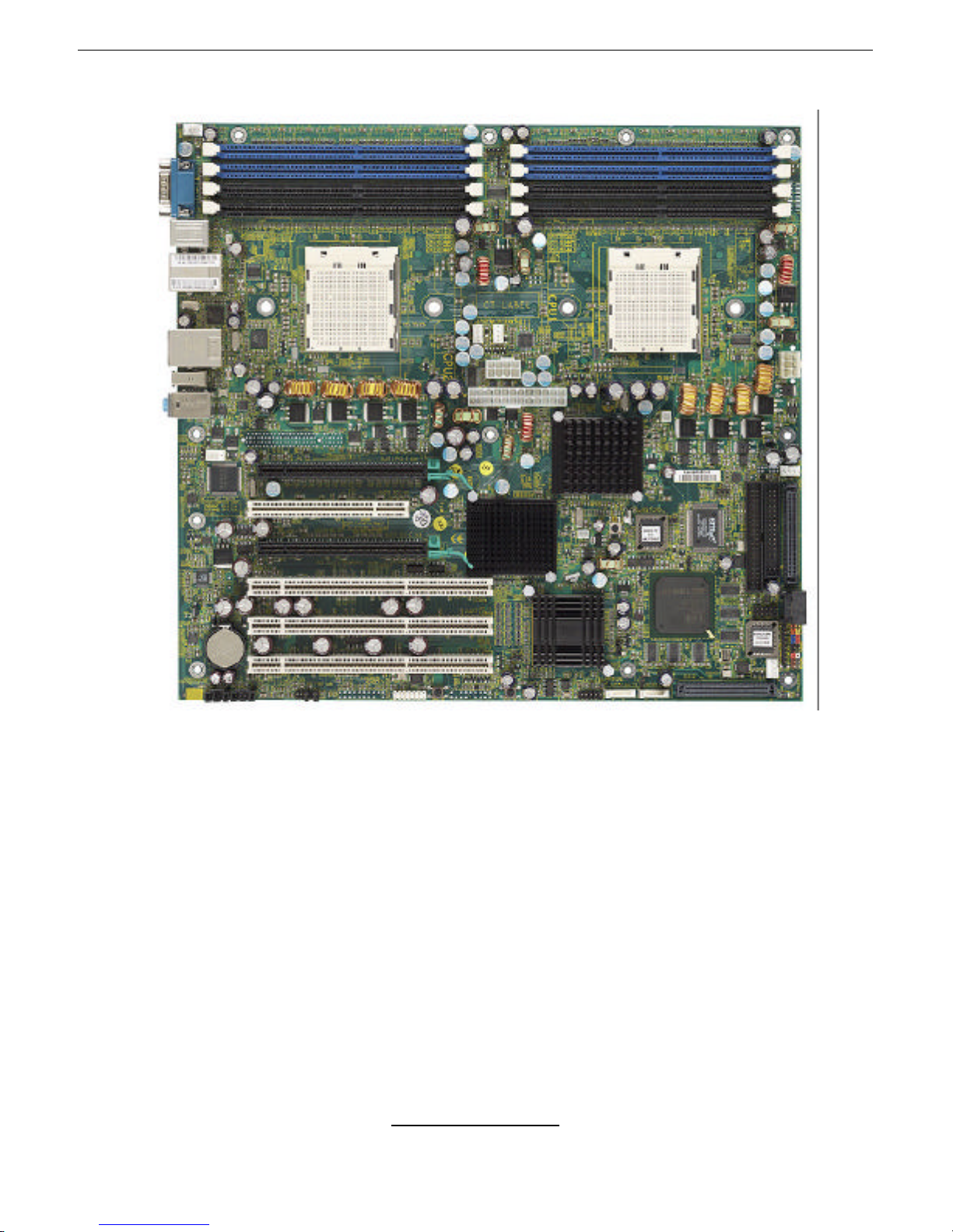
You have purchased one of the most powerful workstation mainboard solutions.
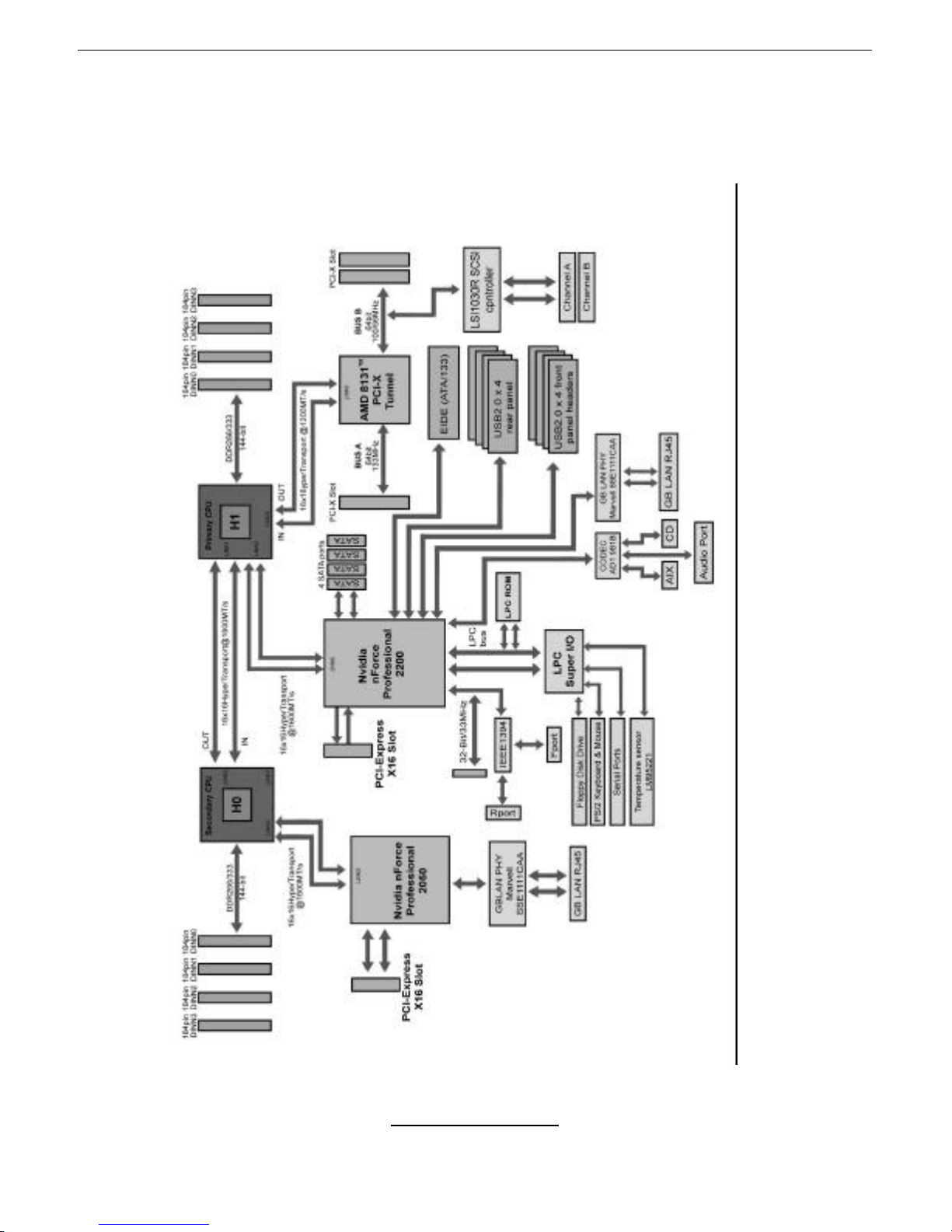
The Thunder K8WE (S2895) is a high-end workstation mainboard, based on
Nvidia nForce Professional 2200 Media and Communications Processor (MCP),
Nvidia nForce Professional 2050, and AMD 8131 PCI-X HyperTransport™
Tunnel.
Designed to support up to two AMD Opteron™(Opteron 2xx) processors and
16GB of DDR333 or DDR400 memory, the S2895 is ideal for CPU, memory,
and video intensive applications such as CAD, Graphics Design, High
Bandwidth Video Editing, etc.
Remember to visit TYAN’s Website at http://www.TYAN.com. There you can
find information on all of TYAN’s products with FAQs, online manuals and BIOS
upgrades.
1.2 -Hardware Specifications
Processor
•Supports one or two AMD
Opteron™2xx processors
•Two onboard 4-phase VRMS
•Three HyperTransportTM links per
CPU, support up to 6.4GB/s data
transfer rate each link
•144-bit DDR interface (128-bit
data + 16 bit ECC)
•Scalable 32bit and 64bit
computing
•Secure computing with Nx register
support
Chipset
•Nvidia nForce Professional 2200
(CK8-04)-connected to CPU1
•Nvidia nForce Professional 2050#
(I/O-4)-connected to CPU2
•AMD 8131™PCI-X Tunnel
•SMsC Super I/O
#Optional
Integrated ATA-133 (from nForce
Professional 2200)
•One ATA-133 IDE Channel for up
to two devices
Integrated SATAII Generation 1
Controllers (from nForce
Professional 2200)
•Two integrated dual port SATA II
controllers
•Four SATA connectors support up
to four drives
•3 Gb/s per direction per channel
•NvRAID v2.0 support
•Supports RAID 0, 1, 5, 0+1 and
JBOD
Integrated Secure Network
Processor
•Two IEEE 802.3 Nvidia MAC
1000/100/10 Ethernet (First from
PRO 2200, Second from PRO
2050)

http://www.tyan.com
4
Memory
•128-bit dual channel (interleaved)
memory bus
•Total Eight DDR-1 DIMM sockets
(Four per CPU)
•Supports up to 16GB Registered
DDR
•Supports ECC with CHIPKil
technology
•Supports DDR400, DDR333, or
DDR266
Expansion Slots
•Two x16 PCI Express full speed
expansion slots
-Slot 1 PCI-E x16 from nForce
PRO 2200
-Slot 3 PCI-E x16 from nForce
PRO 2050
•Two independent 64-bit PCI-X
buses
-Slot 4 and slot 5 support PCI-X
100MHz max
-Slot 6 supports PCI-X 133MHz
max
•One 32-bit 33Mhz PCI v2.3 (Slot
2)
•Total of six usable slots
Integrated I/O
•One floppy connector
•One serial port connector
•Eight USB 2.0 EHCI ports (four
rear connectors & four pin
headers)
•PS/2 mouse and keyboard
connectors
•Two FireWire (IEEE 1394a) ports
(one rear connector and one
internal pin header)
System Management
•Total six 4-pin fan headers with
PWM and tachometer monitoring
•Watchdog Timer support
•Two Marvell Gigabit PHY
•Supports WOL and PXE
•Supports Ethernet Jumbo Frames
(9018 Bytes)
•Full Duplex Gigabit Ethernet
support
•Nvidia Firewall for secure network
communications
Integrated FireWire (IEEE
1394a) Controller
•TITSB43AB22A IEEE 1394a
PCI controller
•Two FireWire ports (one rear
connector and one internal pin
header)
Integrated Audio
•Enhanced AC’97 2.3 compliant
audio link
•Analog Devices 1981B codec
•16 bit Stereo Full Duplex
•CD-in/Aux-in connectors
Integrated SCSI Controller
(Mfg. Option)
•LSI 53C1030 U320 SCSI
controller
-Two U320 68-pin SCSI
connectors
-Connected to PCI-X Bridge B
Form Factor
•SSI EEB v3.5 Footprint (12”x 13”,
304.8x330.2mm)
•EPS 12V/SSI v3.5 Workstation
(24 + 8) power connectors
(Split Plane design
recommended)
•Serial (one)
•Stacked PS/2 keyboard and
mouse connectors
•Two dual port USB2.0 connectors
(total 4 ports)
•Two RJ-45 LAN connectors with
LEDs

http://www.tyan.com
5
•Temperature, voltage and fan
monitoring
•Audio Line-in, Line-out, Mic-in
jacks
•One IEEE 1394a port
BIOS
•PhoenixBIOSon 8Mbit LPC
Flash ROM
•ACPI 2.0
•Serial Console Redirect
•USB device boot
•WOL and PXE support
•48-bit LBA support
1.3 -Software Specifications
OS (Operating System) Support
Microsoft Windows XP (32-bit/64-bit)
Microsoft Windows Server 2003 (32-bit/64-bit)
SUSE Professional 9.x and SLES 9 SP2
RHEL3 Update 4
RHEL4 Update 1
TYAN reserves the right to add support or discontinue support for any OS with
or without notice.

http://www.tyan.com
6
NOTES:

http://www.tyan.com
7
Chapter 2: Board Installation
You are now ready to install your motherboard. The mounting hole pattern of
the Thunder K8WE matches the SSI EEB 3.51 specification. Before continuing
with installation, confirm that your chassis supports anSSI EEB v3.51
motherboard.
How to install our products right… the first time
The first thing you should do is read this user’s manual. It contains important
information that will make configuration and setup much easier. Here are some
precautions you should take when installing your motherboard:
(1) Ground yourself properly before removing your motherboard from the
antistatic bag. Unplug the power from your computer power supply and
then touch a safely grounded object to release static charge (i.e. power
supply case). For the safest conditions, TYAN recommends wearing a
static safety wrist strap.
(2) Hold the motherboard by its edges and do not touch the bottom of the
board, or flex the board in any way.
(3) Avoid touching the motherboard components, IC chips, connectors,
memory modules, and leads.
(4) Place the motherboard on a grounded antistatic surface or on the
antistatic bag that the board was shipped in.
(5) Inspect the board for damage.
The following pages include details on how to install your motherboard into your
chassis, as well as installing the processor, memory, disk drives and cables.
NOTE
DO NOT APPLY POWER TO THE BOARD IF IT HAS BEEN
DAMAGED

http://www.tyan.com
8
2.1-Board Image
This picture is representative of the latest board revision available at
the time of publishing. The board you receive may or may not look
exactly like the above picture.
The following page includes details on the vital components of this
motherboard.

http://www.tyan.com
9
2.2 -Block Diagram
S2895 Thunder K8WE Block Diagram

http://www.tyan.com
10
2.3 -Board Parts, Jumpers and Connectors
This diagram is representative of the latest board revision available at the time of
publishing. The board you receive may not look exactly like the above diagram.
Jumper Legend
©© OPEN -Jumper OFF, without jumper cover
©© CLOSED –Jumper ON, with jumper cover

http://www.tyan.com
11
Jumper/Connector
Function
J14 Chassis Speaker Header
J69 FireWire Disable Jumper
J92 PCI-X-Bridge B Bus Speed Override
J93 COM2 Header
J109 FireWire (IEEE 1394A) Pin Header
J139 Front Panel Header
J142 Reset Button
J143 Power Button
P23 Front Audio Header
P24/P25 USB Front Panel Header
P29 External SCSI LED Header
SW50 Reset CMOS Button

http://www.tyan.com
12
J139: Front Panel Header
SW50:Reset CMOS Button
?In certain cases it may be necessary to reset system
CMOS. Follow these steps:
1) Power off system
HDDLED+ 1¾
¾2PWR LED+
HDDLED-3¾
¾4PWR LED-
Reset SW 5¾
¾6PWR SW
Reset SW 7¾
¾8 PWR SW
+5V 9¾
¾
10
SLEEP SW
NC 11¾
¾12 SLEEP SW
+5V Standby 13¾
£14 NC (KEY)
SMBUS DATA 15¾
¾16 GND
SMBUS CLOCK 17¾
¾18 Chassis Intr# (Active
Low)
SW50
J92
J109
P24
J93
P25
J139

http://www.tyan.com
13
2) Press SW50 for 5 seconds
3) Power system and enter BIOS setup
P24, P25: USB Front Panel Header
©©
©©
©©
©©
£©
Signal Pin Pin Signal
VCC 12VCC
Data -34Data -
Data + 56Data +
GND 78GND
KEY 910 GND
J92:PCI-X Bridge Bus Speed Override
©©
©©
Open-(Default) Allows PCI Bridge B (Slots 4, 5 &
Devices) to operate at up to 100MHz
Closed-Force PCI Bridge B (Slots 4, 5 & Devices) to
operate at a maximum 66MHz
NOTE: This jumper affects integrated SCSI on the
same bus.
J109: FireWire (IEEE1394A) Pin Header
©£
©©
©©
©©
©©
©©
©£
Signal Pin Pin Signal
NC1 12Key
TPA + 34TPA -
GND 56GND
TPB + 78TPB -
+12V 910 +12V
GND 11 12 GND
NC2 13 14 Key
J93: COM2 Header
©©©
Use these pin definitions to connect a port to
COM2*
Pin1 COM2 Receive
Pin2 COM2 Ground
Pin3 COM2 Transfer
*TYAN does NOT provide cable for this header. It is
designed for OEM use only.

http://www.tyan.com
14
P23
J69
J14
P29

http://www.tyan.com
15
P23: Front Audio Header
Signal Pin
Pin
Signal
MIC_L 12GND
MIC_R 34VCC-
LINE_FPOUT_R 56LINE_OUT_R
AUD_DET
78KEY
LINE_FPOUT_L
910
LINE_OUT_L
The front panel Audio comes preinstalled with jumpers on pins 5-6 and 9-10.
Remove these jumpers to place a front panel audio cable
WARNING: Do not place jumper covers on this header in any other
configuration. Doing so could result in damage to the motherboard
J69: FireWire Disable Jumper
©©
©©
Open-(Default) Enables onboard FireWire controller
Closed-Disables onboard FireWire controller
J14: Onboard Buzzer/Speaker Header
4
1
Close Pin-3 and 4 (Default)-Onboard buzzer enabled.
4
1
Open Pin-3 and 4-Disable onboard buzzer or connect
to chassis speaker
P29: External SCSI LED Header
4
1
Use to connect external SCSI LED
Pin 1: NC, Pin 2: LED, Pin 3: LED, Pin 4: NC

http://www.tyan.com
16
FAN4
FAN3
FAN2
CPU1 Fan
CPU2 Fan
FAN1

http://www.tyan.com
17
Fan Connectors
The S2895 uses the standard 4-wire cooling fan connector pin-out. The
connector is keyed to prevent damage to the mainboard and fan due to
misalignment during insertion. Fans are 12V nominally rated with fan speed
modulated by the control signal. The Sense signal is a fan tachometer output
signal with two pulses per revolution. The Control signal is a 25KHz Pulse Width
Modulated (PWM) signal from the baseboard control circuitry.
The 4-wire fan is forward and backward compatible to the 3-wire fan. This
means an older 3-wire fan will plug into a 4-wire fan header. However, there is
no speed control for a wire fan. It will always run at full RPM
1 2 3 4
©©©©
Pin1=GROUND
Pin2= +12v
Pin3= Tachometer
Pin4= Speed Control
Use these headers to connect the processor or
chassis cooling fan to your motherboard to keep the
system stable and reliable.
* For 3-pin fans connect to pin 1-3.
Hardware Monitor
Temperature senor
Senor chip: LM95221 (SMB address: 010 1011x)
CPU1temperature: U92 pin1, 2
CPU2temperature: U92 pin3, 4
FAN speed detect and control
CPU1FAN CPU1 FAN PWM: SIO PIN34 GP11
CPU1 FAN TACH: SIO PIN7 GP85
CPU2 FAN CPU2 FAN PWM: SIO PIN43 GP22
CPU2 FAN TACH: SIO PIN110 FAN_TACH4
FAN 1 FAN1PWM: CK804 PINAB4 FANCTL1
FAN1TACH: CK804 PINAA3 FANRPM
FAN 2FAN2 PWM: SIO PIN104 GP74
FAN2 TACH: SIO PIN35 FAN_TACH2
FAN 3 FAN3PWM: SIO PIN104 GP74
FAN3TACH: SIO PIN103 FAN TACH3
FAN 4 FAN4PWM: CK804 PINAA2 FANCTL0
FAN4TACH: CK804 PINAA3 FANRPM

http://www.tyan.com
18
2.4-Installing the Processor(s)
Your brand new Thunder K8WEsupports the latest 64-bit processor technology
from AMD. Only AMD Opteron™processor 200 series are certified and
supported with this motherboard.
Check our website for latest processor support. http://www.tyan.com
NOTE If using a single processor, it MUST be installed in socket
CPU1. When using a single processor only CPU1 memory
banks are addressable.
TYAN is not liable for damage as a result of operating an unsupported
configuration.
The diagram is provided as a visual guide to help you install socket processors
and may not be an exact representation of the processors you have.
Step 1: Lift the lever on the socket until it is approximately 90o or as far back as
possible to the socket.
Step 2: Align the processor with the socket. There are keyed pins underneath
the processor to ensure that the processor’s installed correctly.
Step 3: Seat the processor firmly into the socket by gently pressing down until
the processor sits flush with the socket.
Step 4: Place the socket lever back down until it locks into place. The
installation is finished.
Repeat these steps for the second processor if you are using two processors.
Take care when installing processors as they have very fragile connector pins
below the processor and can bend and break if inserted improperly.
NOTE In order to access PCI Express x16 slot 3and second Nvidia
MAC,TWO CPUs must be installed.

http://www.tyan.com
19
2.5-Heatsink Retention Frame Installation
After you are done installing the processor(s), you should proceed to installing
the retention frame and heatsink. The CPU heatsink will ensure that the
processors do not overheat and continue to operate at maximum performance
for as long as you own them. Overheated processors are also dangerous to the
motherboard.
The backplate assembly prevents excessive motherboard flexing in the area
near the processor and provides a base for the installation of the heatsink
retention bracket and heatsink.
Because there are many different types of heatsinks available from many
different manufacturers, a lot of them have their own method of installation. For
the safest method of installation and information on choosing the appropriate
heatsink, use heatsinks validated by AMD. Please refer to AMD’s website at
www.amd.com.
The following diagram will illustrate how to install the most common CPU back
plates:
1. Mounting screws
2. Heatsink retention frame
3. CPU socket
4. Motherboard PCB
5. Adhesive insulator
material
6. Backplate assembly
NOTE: Please see next
section for specific
instructions on how to install
mounting bracket.

http://www.tyan.com
20
2.6-Thermal Interface Material
There are two types of
thermal interface materials
designed for use with the
AMD Opteron processor.
The most common material
comes as a small pad
attached to the heatsink at
the time of purchase. There
should be a protective cover
over the material. Take care
not to touch this material.
Simply remove the protective
cover and place the heatsink
on the processor.
The second type of interface
material is usually packaged
separately. It is commonly
referred to as ‘thermal
compound’. Simply apply a
thin layer on to the CPU lid
(applying too much will
actually reduce the cooling).
NOTE
Always check with the manufacturer of the heatsink &
processor to ensure the Thermal Interface material is
compatible with the processor & meets the manufacturer’s
warranty requirements
This manual suits for next models
2
Table of contents
Other TYAN Motherboard manuals

TYAN
TYAN TIGER I7501X User manual

TYAN
TYAN S7070 User manual

TYAN
TYAN B7018Y290D2 User manual

TYAN
TYAN S1832DL User manual

TYAN
TYAN S7067 User manual

TYAN
TYAN THUNDER 2400 User manual

TYAN
TYAN Thunder i7500 Pro S2721 User manual

TYAN
TYAN S7066 User manual

TYAN
TYAN Tiger 230T S2507T User manual

TYAN
TYAN S8020 User manual

TYAN
TYAN Thunder n3600M (S2932) User manual

TYAN
TYAN S5517 User manual

TYAN
TYAN THUNDERBOLT User manual

TYAN
TYAN TIGER K8W User manual

TYAN
TYAN THUNDER N4250QE User manual

TYAN
TYAN S1854 Trinity 400 User manual

TYAN
TYAN TOMCAT K8E User manual

TYAN
TYAN Tomcat i945GM S3095 User manual

TYAN
TYAN S5565 User manual

TYAN
TYAN S7076 User manual