Tyco Electronics 262-300 User manual

Installation and Operating Manual
262-300 Process Control
Digital Meter Relay
http://energy.tycoelectronics.com
Energy Division
Tyco Electronics UK Limited
Crompton Instruments
Freebournes Road, Witham, Essex, CM8 3AH, UK
Tel: +44 1376 509 509
Fax: +44 1376 509 511

Crompton
262-300 Process Control
Digital Meter Relay
Installation & Operating Manual
Crompton Instruments
Freebournes Road
Witham
Essex
CM8 3AH
England
Tel: +44 (0) 1376 509 509
Fax: +44 (0) 1376 509 511
E-Mail: [email protected]
Crompton Instruments 262-300WEB Issue 1 11/2002

Contents Page
1.0 General 1 - 2
2.0 Unpacking 2
3.0 Installation 3 - 6
3.1 Safety Information 3
3.2 nstalling Into a Panel 4
3.3 Wiring 4
3.4 Power Supply 4 - 5
3.5 Sensor Connections 5
3.5.1 Current Measurement of an 5
Internally Powered Loop
3.5.2 Current Measurement of an Externally 6
Powered Loop
3.5.3 Voltage Connection 6
4.0 Programming the Instrument 7 - 10
4.1 Programming Guide 7
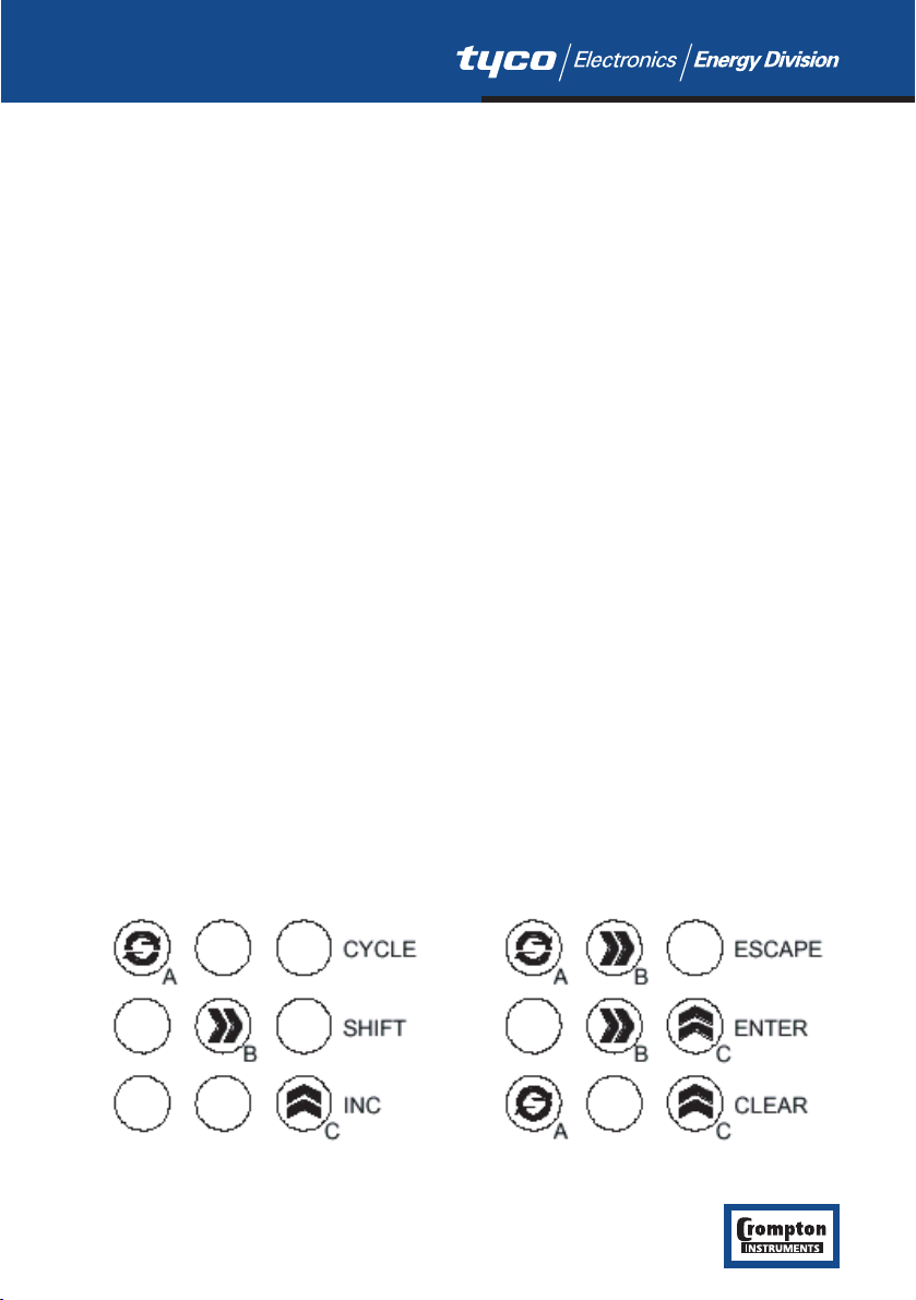
4.2 Key Definitions 7
4.3 Entering Menu Mode 8
4.3.1 Moving Around The Menu 8
4.3.2 Entering A Submenu 8
4.3.3 Editing A Parameter 9
4.3.4 Returning From Submenus 9
4.4 The Menus
4.4.1 The INPt (INPUT) Submenu 10
4.4.2 The SyS (System) Submenu 10
5.0 Operation 11
5.1 Run Mode Operation 11
5.2 Failure Modes 11
6.0 Specification 11
6.1 Process Specification 11
6.2 General Specification 11 - 12
7.0 Option Modules 12 - 16
7.0.1 Installing Modules 12
7.1 262-RLY Dual Relay Module 13
7.1.1 SLT1, SLT2 (Relay Module) Submenu 13
7.1.2 Relay Specification 13
7.2 2 62-ALG, Isolated Analogue Output Module 14
7.2.1 SLT1, SLT2 (Analogue output 14
module) Submenu
7.2.2 Analogue output module Specification 14
7.3 Modbus Serial Communications Module, 15
262-MOD
7.3.1 SLT1, SLT2 (Communications) Submenu 15
7.3.2 Comms Module Specification 15 - 16
8.0 Mechanical Detail 17

1.0 General
The unit is a highly accurate and stable digital temperature indicator that accepts all commonly
used temperature sensors. The unit can be used "stand alone" or, with the Modbus serial
communications module option, as part of a larger system.
The case design enables option Modules to be easily installed without the need for dismantling
or re-calibration. A range of Modules are available for:
●Relay outputs 262-RLY
●Isolated Analogue Output 262-ALG
●Modbus serial communication 262-MOD
1

1.0 General continued
The diagram shows the rear panel positions for all electrical connections.
2.0 Unpacking
Please inspect the instrument carefully for any signs of shipping damage. The packaging has
been designed to afford maximum protection, however, we cannot guarantee that mishandling
will not have damaged the instrument. In the case of this unlikely event, please contact your
supplier immediately and retain the packaging for subsequent inspection.
2

3.0 Installation
THIS SECTION FOR USE BY COMPETENT PERSONNEL ONLY
3.1 Safety Information
WARNING READ SAFETY INFORMATION BELOW BEFORE INSTALLATION
WARNING Hazardous voltages may be present on the terminals the
equipment must be installed by suitably qualified personnel and
mounted in an enclosure providing protection to at least IP20.
ISOLATION The power supply terminals and associated internal circuitry are
isolated from all other parts of the equipment in accordance
with BS EN61010-1 for connection to a Category II supply
(pollution degree 2).
Functional isolation (500v max) is provided between input and
output circuits, and between inputs and communications
(where fitted).
Any terminals or wiring connected to the input, output or
communications terminals which are accessible in normal
operation must ONLY be connected to signals complying with
the requirements for Safety extra low voltage (SELV) circuits.
WARNING If not installed in accordance with these instructions, protection
against electrical hazards may be impaired.
●Installation overvoltage category - 2 (as per BS EN61010-1)
●The Mains supply to the equipment must be protected by an external 1 Amp fuse and a
suitable switch or circuit breaker which should be near the equipment.
●The equipment contains no user serviceable parts.
3

3.2 Installing Into a Panel
Refer to section 8.0 for Mechanical Detail.
The maximum panel thickness is 10mm. The instrument case has an integral gasket which
forms a seal when the instrument is tightened against the panel.
The panel should be clean, smooth and at least 1.6mm thick for the seal to be effective.
●WARNING Use only the retaining screws provided to clamp the instrument
to the panel ( screws must be tightened sufficiently to effect a
seal but must never be overtightened).
3.3 Wiring
All connections are made to sockets which are removable for ease of maintenance. Installation
should be undertaken in accordance with relevant sections of BS6739 - British Standards code of
practice for "Instrumentation in Process Control Systems: Installation design and practice".
3.4 Power Supply
The Power supply rating will be indicated on the top of the instrument, ensure it is correct for
the application. The Mains supply to the equipment must be protected by an external 1 Amp
fuse and a suitable switch or circuit breaker which should be near the equipment.
4

3.4 Power Supply Continued
Wires are retained by screws. Ensure that the exposed section of the wire is fully inserted and
that no loose strands are exposed.
3.5 Sensor Connections
All sensor connections are made via a five way "fast wiring" socket at the rear of the unit (wire
size 0.5 to 1.5mm2).
3.5.1 Current Measurement of an Internally Powered Loop
A 24V internal power supply is available to power external field transmitters.
5

3.5.2 Current Measurement of an Externally Powered Loop
3.5.3 Voltage Connection
6

To make a connection: Insert small screwdriver blade into tension clamp orifice, (1) push and
twist to deflect clamp into open position. Do not lever screwdriver thus forcing connector body
sideways. Insert conductor tail sufficiently into (2) then release screwdriver. Ensure no loose
wire strands protrude.
4.0 Programming the Instrument
The unit is a microprocessor based instrument enabling it to satisfy a variety of applications. All
programming is available from the front panel or via a PC using the RS485 Modbus
communications module.
4.1 Programming Guide
The unit has three operating modes. These are :
●RUN (DISPLAYS PROCESS VARIABLE)
●MENU
●EDIT
RUN is the principal mode of operation, which displays the Process Variable from which all
other modes are accessed. The unit will always time-out back to this mode after one minute.
MENU mode provides access to the programmable parameters.
EDIT mode is entered from Menu Mode and allows the user to inspect and modify a parameter.
4.2 Key Definitions
The indicator is programmed using the three front panel keys, A,B and C are shown to assist the
tutorial.
CYCLE (A), SHIFT (B) and INC (C) keys are pressed singularly.
ESCAPE (A&B), ENTER (B&C) and CLEAR (A&C) are obtained by simultaneously pressing the
two keys.
7

4.3 Entering Menu Mode
The Root Menu mode is accessed from "Run" by pressing ENTER (B&C) followed by CYCLE (A).
The display will now show "inPt". In order to understand what this means, the following
diagram shows where we are within the basic Root menu.
* Slot menus only appear when respective option modules are fitted.
4.3.1 Moving Around The Menu
One can browse through the Root menu by pressing CYCLE (A) which moves the menu position
from left to right (after reaching SYS, the menu position wraps around to the start).
4.3.2 Entering A Submenu
To enter a submenu, first cycle around the Root menu until the required submenu is displayed.
For the purposes of this tutorial press the CYCLE (A) key until InPt is displayed. Pressing SHIFT
(B) enters the Input Submenu.
tYPe will now be displayed. The diagram shows our position in relation to other items in the
menu.
Pressing CYCLE (A) moves left to right, wrapping around at the end. The unit alters items in the
menu list depending upon settings made.
8

4.3.3 Editing A Parameter
The items displayed in the menu can either be submenus, parameters or
numbers, most of the items in the Inputs menu are parameters which can be
edited.
Press the CYCLE (A) key until tYPe is displayed, then press SHIFT (B).
The current setting will now be shown flashing. This item is changed by pressing
the INC (C) key.
The choice of options available is as follows:
Press the INC (C) key until "crnt" is displayed.
Note that whilst the display is flashing, the option on the display has not been
saved to memory. To select an option, the ENTER key sequence is used. Press
ENTER (B&C). The display will stop flashing momentarily before returning to
Menu mode. The system automatically steps on to the next entry to speed the
process of programming. This method of editing parameters is repeated
throughout the menu structure.
4.3.4 Returning From Submenus
To return up from the inPt menu to the root menu wait for 1 minute or press the ESCAPE (A&B)
key.
Pressing the ESCAPE key from our current position in the Inputs submenu takes us back to the
Root menu. The menu position will automatically step to the next menu item, if no modules are
fitted the unit will show SYS, if modules are fitted SLt1 or SLt2 will be shown.
9

The Root menu, as its name suggests is not a submenu. Pressing the ESCAPE (A&B) key
sequence whilst in the Root menu will take the user out of Menu mode and into Run mode.
Thus the process variable will be shown on the display. Refer to section 5.2 if an error code is
shown after programming in menu mode.
4.4 The Menus
4.4.1 The INPt (INPUT) Submenu
The INPt submenu is used to program all the characteristics of the input sensor and any signal
conditioning that may be required. The selection of an option in the list may affect items further
down. Therefore, during programming, the user should start at the top of the menu and work
down, to avoid setting an option which may later become obsolete. Short menu items shown in
bold.
TITLE OPTIONS DETAIL
tYPE crnt, VoLt Set Current or Voltage
dP 888.8, 88.88, 8.888, 8888 Defines decimal point location
rngE 4-20, 0-20, 0-10 mA range setting, only for Current input
rngE 1-5, 0-1, 0-10 Voltage setting, only for Voltage input
Lo 000.0 Low engineering range, -999 to 9999
Hi 100.0 High engineering range, -999 to 9999
Lin nonE, Sqrt, cust Linearity: none, square root or custom *
FiLt nonE, 2.5s, 10s, Adaptive Input filtering or smoothing
* It is only possible to define custom characteristics via comms.
4.4.2 The SyS (System) Submenu
TITLE OPTIONS DETAIL
LiSt FuLL, SHrt Selects full or short menu
cLEn oFF, on Clear enable (option modules)
SPEn oFF, on Setpoint enable (option modules)
PASS 4 digit passcode Modify any password code
oFFS User defined offset Take care when replacing sensor
Refer to section 7.0 for SLt menu structures.
10

5.0 Operation
5.1 Run Mode Operation
The normal display shown in this mode is the process variable.
KEYPRESS ACTION
CYCLE (A) View setpoints (Adjust value if SPEn enabled)
CLEAR (A&C) Clear latched alarms (cLEn enabled)
5.2 Failure Modes
If the input is outside the measuring
range of the instrument, the following
error messages will be shown.
6.0 Specification @20 °C
6.1 Process Specification
Voltage Range 0-1 volts / 1-5 volts / 0-10 volts
Accuracy 0.05% FS
Thermal Drift Zero 0.1µV / °C
Span 100 ppm / °C
Current Range 0-20mA / 4-20mA / 0-10mA
Input Impedance 47 ohm (current)
1 Mohm (voltage)
Accuracy 0.05% FS
Thermal Drift 100 ppm / °C
Excitation 24V ±5% @ 50 mA
6.2 General Specification @ 20 °C
Input/Output Isolation 500VAC rms (galvanically isolated)
Update time 250 mS maximum
Time Constant (Filter off) <1 second (to 63% of final value)
Filter Factor Off, 2 Seconds, 10 Seconds or Adaptive
Warm-up time 2 minutes to full accuracy
Display Range -999 to 9999
Power Supply 90-253 VAC 50/60 Hz, or optionally 20-35 VDC
Power Consumption 6VA Maximum (options fitted)
11

Environmental
Sealing to PANEL IP65
Ambient Operating Range -30 to +60 °C
Ambient Storage Temperature -50 to +85 °C
Ambient Humidity Range 10 to 90% RH non condensing
APPROVALS
EMC Emissions BS EN50081-1
Susceptibility BS EN50082-2
ELECTRICAL SAFETY BS EN61010-1
Environmental Approvals for Tension Clamp Terminals
Low Temperature IEC 68-2-1
Dry Heat IEC 512-6-9
Damp Heat IEC 512 -6-3
Damp Heat cyclical IEC 68-2-30
Salt Spray IEC 512-6-6
Sulphur Dioxide IEC 68-2-46
Hydrogen Sulphide IEC 68-2-16
Gas Tightness IEC 512-Pr.11n
7.0 Option Modules
7.0.1 Installing Modules
Power must be removed from unit before adding/removing a module.
Slot 1 (alarm 1 and 2) should be positioned on the left side of the unit looking from the front to
correspond to front panel alarm indicator, slot 2 (alarm 3 and 4) is positioned on the right.
To install an option module, slide back the cover to its next engaging position and push the
module connection within the mating connector.
To remove an option module, disengage the supporting latch situated beneath the module by
pushing the back cover forward, the module can then be lifted away from the instrument
connector.
12

7.1 262-RLY Dual Relay Module
The relay module has two "change over" relays with a common wiper.
7.1.1 SLT1, SLT2 (Relay Module) Submenu
Each relay can be set as high or low alarm independently.
TITLE OPTIONS DETAIL
AL1 Hi, Lo Alarm action
SEt1 User defined PV at which the alarm triggers
HYS1 User defined Hysterisis band (see below)
LAt1 oFF, on Sets latching to on or off
inUI oFF, on Invert relay operation
Continues through for Relays 2 - 4 (when fitted).
Short menu items shown in bold.
Hysteresis Operation
7.1.2 Relay Specification
AC DC
Maximum Load 7A @ 250V 7A @ 30V
Maximum Power 1750VA 210W
Maximum Switching 250V 125V
Electrical Life 105operations at rated load
Mechanical Life 50 Million operations
13

7.2 262-ALG, Isolated Analogue Output Module
The re-transmission module (when fitted) is designed to provide 0-10mA, 0-20mA or 4-20mA
output in active or passive modes. The output can be any portion of the display. The module can
be used in two modes:
Note: Only one analogue output module can be fitted.
7.2.1 SLT1, SLT2 (Analogue output module) Submenu
TITLE OPTIONS DETAIL
SPan 4-20mA, 0-20mA, 0-10mA User defined output current
rt lo User defined Low span range, to match display
rt HI User defined High span range, to match display
7.2.2 Analogue output module Specification
Minimum Current Output > 0mA
Maximum Current Output < 23mA
Accuracy 0.07% or 5µA, which ever is greater
Maximum External Power Supply 30V (passive mode)
Voltage Effect 0.2µA / V
Ripple Current <3µA
Isolation 500V AC
Temperature Stability 1µA / °C
14

7.3 Modbus Serial Communications Module, 262-MOD
The diagram below shows a PC connected to Modbus modules.
7.3.1 SLT1, SLT2 (Communications) Submenu
TITLE OPTIONS DETAIL
Addr User defined Instrument device number
baud 9.6, 19.2 User selected baud rate
Line 2, 4 4 Wire or 2 wire half duplex RS 485
7.3.2 Comms Module Specification
Configuration, system I/O and display unit PC communication.
Physical Layer 4 wire or 2 wire half duplex RS485
Isolation 500V AC
Maximum Fan out 32 units
Software Baud Rate 19,200 or 9,600
Protocol Modbus RTU format
15

* Connection of the link connects a 100 ohm termination resistor across pins 7 and 8. This
resistor should only be selected for the instrument furthest away from the host.
Full details of the modbus protocol are supplied separately with the module.
16

8.0 Mechanical Detail
Material ABS/PC
Weight 200g
Flammability IEC707 FV0
Module weight 40g typical
Panel cutout 92mm x 45mm
17
Table of contents
Popular Relay manuals by other brands

Pilz
Pilz PNOZ s7 Series operating instructions

Eaton
Eaton Digitrip RMS 510 LI instruction manual

ICM Controls
ICM Controls ECA PRODUCTS ECAIOO-II installation instructions

LEGRAND
LEGRAND Wattstopper LMCP-GE24 installation instructions

Siemens
Siemens SIPROTEC 7SD610 user manual

TIS
TIS RLY-4CH-10A Manual Installation