409- 10096
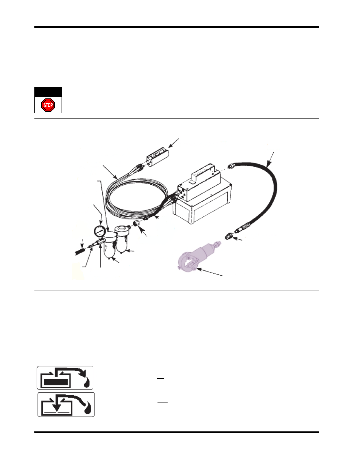
Air- Powered Hydraulic Pump 2119010- 1
Rev A4 of 9 Tyco Electronics Corporation
2. SAFETY PRECAUTIONS
General Operation
SAll DANGER statements must be carefully observed to help prevent personal injury.
SBefore operating the pump, all hose connections must be tightened with the proper tools. Do not over-
tighten. Connections should only be tightened securely and leak--free. Overtightening can cause
premature thread failure or high pressure fittings to split at pressures lower than their rated capacities.
SShould a hydraulic hose ever rupture, burst, or need to be disconnected, immediately shut off the pump
and release all pressure. Never attempt to grasp a leaking pressurized hose with your hands. The force
of escaping hydraulic fluid could cause serious injury.
SDo not subject the hose to potential hazard such as fire, sharp surfaces, extreme heat or cold, or heavy
impact. Do not allow the hose to be altered or kink, twist, curl, crush, cut, or bend so tightly that the fluid
flow within the hose is blocked or reduced. Periodically inspect the hose for wear, because any of these
conditions can damage the hose and possibly result in personal injury.
SDo not use the hose to move attached equipment. Stress can damage hose and possibly cause person-
al injury.
SHose material and coupler seals must be compatible with the hydraulic fluid used. Hoses also must not
come in contact with corrosive materials such as creosote--impregnated objects and some paints. Con-
sult the manufacturer before painting a hose. Hose deterioration due to corrosive materials can result in
personal injury. Never paint the couplers.
SInspect machine for wear, damage, and correct function before each use. Do not use machinery that is
not in proper working order, but repair or replace it as necessary.
SReplace worn or damaged safety decals.
SDo not modify the product.
SUse only components with the same pressure rating when assembling a system or machine.
Pump
SDo not exceed the hydraulic pressure rating noted on the pump data plate or tamper with the internal
high pressure relief valve. Creating pressure beyond the rated pressure can result in personal injury.
SBefore replenishing the fluid level, retract the system to prevent overfilling the pump reservoir. An overfill
can cause personal injury due to excess reservoir pressure created when cylinders are retracted.
Air Supply
SShut off and disconnect the air supply when the pump is not in use or before breaking any connections
in the system.
3. OPERATING PRECAUTIONS FOR THE PUMP
1. When connecting the coupler, be sure that no foreign objects are attached. If the coupler has become
dirty, clean it carefully before connecting it. Engaging the coupler when foreign objects are present will
damage the seals and lead to oil leakage from the connection.
2. Make sure that the coupler is securely connected. If the unit is pressurized while the coupler is not
properly connected, there will be damage to the seals or the crimp head.
3. Although a flexible hydraulic hose is used, do not bend it while pressure is being applied, or subject
the hose to shocks from metal objects. Either of these will shorten the working life of the hose and may
result in the hose bursting.
4. Never move the pump by pulling on the hydraulic hose or the remote control cords.
5. To ensure smooth operation of the pump, always use the pump after it has been stored for at least
one hour at 10°Cto25°C. If the pump is stored for an extended period below --5°C, viscosity of the oil
increases.
DANGER