5BI
R
+
-
L2
L
-
+
TYCO
MX c.i.e.
AL
AR
L1
TYCO
E500Mk2
REMOTE
INDICATOR
R
LL1
L2
M
R
L
L1
L2
R
L
M
L1
L2
R
L2
LL1
M
R
L
L1
L2
5BI5B
M
M
5B
R
L
R
L
M
L1
L2
L1
L2
-
+
DETECTOR ADDRESS
The address label carrier is fitted to the detector before mounting on the
base. When the detector is mounted to the base, and turned clockwise
until fully located on the base, the address label carrier is transferred to
the base. If the detector is removed the address label carrier remains on
the base.
Part Number Desc.
516.800.915 Label Carrier
516.800.931 White Label
516.800.932 Yellow Label
516.800.933 Purple Label
516.800.934 Green Label
www.tycosafetyproducts-anz.com
Tyco Safety Products, a division of Tyco Australia Pty Limited
A.B.N. 80 008 399 004, reserve the right to alter specifications without
notice, in line with Tyco’s policy of continuing product improvement.
INSTALLATION
The 814 series of detectors are not suitable for use where they may
be exposed to condensing moisture, mist or water spray.
When mounting on a damp surface or narrow beams where
condensation may enter the rear of the detector, the deckhead
mounting base DHM5B (part no. 517.050.603) or similar should
be used. The 814CH should not be positioned where high localised
levels of CO may normally occur, e.g. indoor car parks, warehouses.
The 814H Heat detector may be more appropriate. Installation of all
detectors should be carried out in accordance with AS 1670.1/
NZS 4512. Cable penetrations should be sealed when positive or
negative pressures in ceiling spaces may affect the performance or
contaminate the installed detectors.
MAINTENANCE AND SERVICE
The Tyco MX addressable system should be maintained in accordance
with AS 1851/NZS 4512. The Tyco X300 Smoke Tester, X461
Heat Tester and CO Test Gas (part no. 517.001.262) may be used for
testing in-situ. Rotating the detector anticlockwise past an indent to
the park position disconnects the detector from the circuit whilst still
retaining it in the base, allowing wiring testing etc. Note that insulation
testing must not be done when isolator bases are used.
Depressing the plunger at the side of the base allows the detector to
be rotated back into its operating position. Wormald Detector Clean &
Calibrate Wollongong are able to check the calibration of MX detectors.
Additionally, although the 814CH has an expected life in excess of
10 years, in order for the 814CH to provide the intended level of fire
detection, the detector should be checked for calibration 5 years after
installation or within 7 years of the date of manufacture.
Applications Warning In many fires, hazardous levels of smoke
and toxic gas can build up before a heat detection device will initiate
an alarm. In cases where life safety is a factor, the use of smoke
and/or CO detection is highly recommended. Heat detectors are not
considered to provide life safety protection and are generally used
where property protection is desired, but smoke or CO detectors cannot
be used. Typical heat detector applications are satisfied by the use of
rate-of-rise and fixed temperature electronic detectors. The addition
of rate-of-rise operation provides faster heat detection for use where
temperature fluctuations are controlled and less than 6°C/min. Where
temperatures may fluctuate more quickly, use fixed temperature
detection only (Type B or Type D).
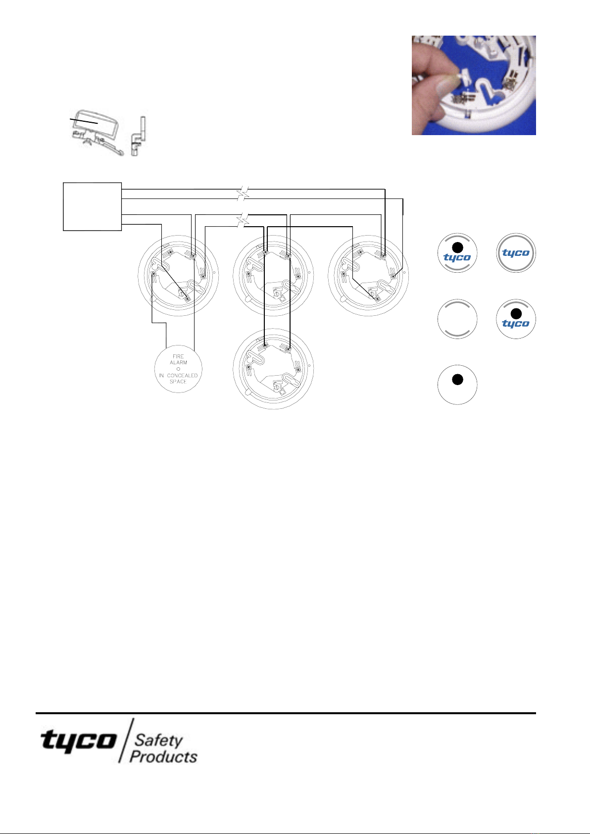
All wiring terminates at the 5B or 5BI base as follows:
R: – Remote L: – In and Out L1: + In, Out & Remote M: – In (5BI only) L2: – Out (5BI only)
Cables should be arranged at each side of the terminal screw. A maximum of two 1.5mm2 cables or one 2.5mm2 cable can
be fitted to one terminal. Any additional cables (such as Remote Indicator) should be fitted with suitable fork or eyelet crimp
terminal lugs. The installation should comply with AS 1670.1/NZS 4512.
Note that alarm zone circuits with more than 40 devices must be wired as a loop and use isolator bases in accordance
with the design manuals. Refer to the relevant information sheet for base wiring details.
LOCKING KEY
A detector locking device is
moulded into the 5B base. This
must be detached and inserted
into the locking aperture if
required, prior to the selected
detector being installed. The
detector may then be removed
only by inserting an unlocking tool
(a Ø3 x 22mm long rod) into the
hole on the detector cover to depress the locking device.
5 June 2009
120.415.744 Issue 13 ©Tyco Safety Products - Fire Detection - ANZ Region Page 2 of 2
WIRING
tyco
814PH 814I
814P 814CH
814H
DETECTOR
IDENTIFICATION
Each detector is identified
by a unique label on the
top, as shown:
The MX c.i.e. can
be programmed to
illuminate a Remote
Indicator for detectors
other than the detec-
tor base to which it is
connected.
tyco
ADDRESS
FLAG
AFFIXED
HERE


