18
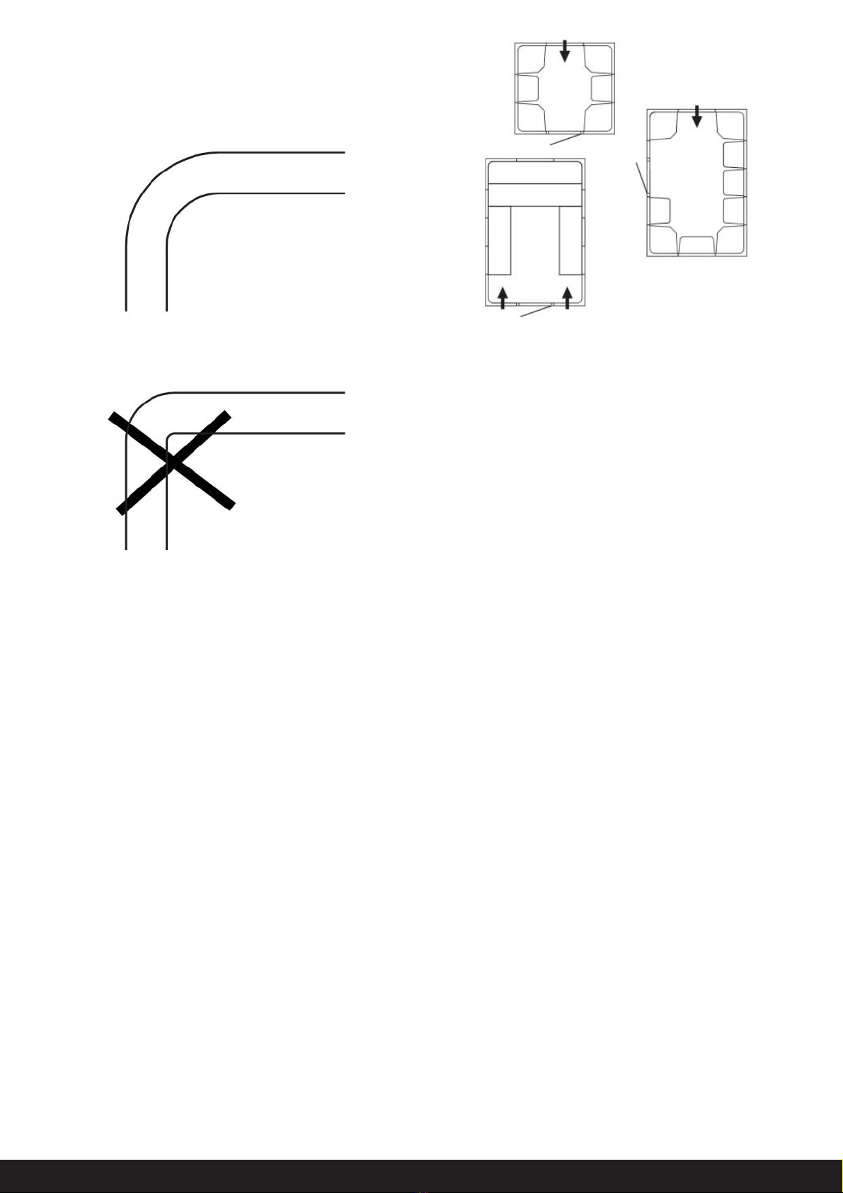
• The steam piping must not have any sharp bends.
• Do not direct the steam jet against walls, seats or other
objects. Always keep a space of at least 80 cm clear in front
of the steam nozzle.
• There must not be any water pockets in the steam piping
or ventilation ducts. IMPORTANT! There must not
be any kind of blockage in the steam piping (e.g. taps or
valves). The internal diameter of the steam piping must not
be reduced.
• All steam rooms in continuous use for more than two hours
must have an air exchange rate of 10-20 m³ air per person
per hour.
• The power supply for the steam generator must not be cut
off. Therefore avoid installing a power switch, etc. in the
power supply line.
• The drain pipe must have a continuous fall all the way from
the steam generator to the drain.
• The ambient temperature for the steam room and steam
generator must not exceed 35°C.
• The sensor must be located as far from the steam jet as
possible.
• Descale the steam generator regularly in accordance with
the instructions, refer to the heading ”Descaling”. In areas
with hard water, exceeding 4°dH hardness, a water softener
or Tylö MACH 2020 water softener must be installed (Tylö
Item no. 9090 8025)
• Clean the steam room regularly
• NB! The steam generator drain must always lead to a
drainage channel outside the steam room. The steam gene-
rator empties its tank 1 hour after each bath, The water will
then be 80-85°C!.
• WARNING! There is a jet of hot steam from the ste-
am nozzle. Never leave small children unattended.
• This equipment is not intended to be used by anyone (in-
cluding children) with a mental or physical disability or little
experience or knowledge of how to use it, unless instructed
or supervised by someone responsible for their safety.
• This appliance can be used by children aged from 8 years
and above and per¬sons with reduced physical, sensory or
mental capabilities or lack of experience and knowledge if
they have been given supervision or instruction concern-ing
use of the appliance in a safe way and understand the
hazards involved.
• Children shall not play with the appli¬ance.
• Cleaning and user maintenance shall not be made by child-
ren without supervision.
IMPORTANT!
General
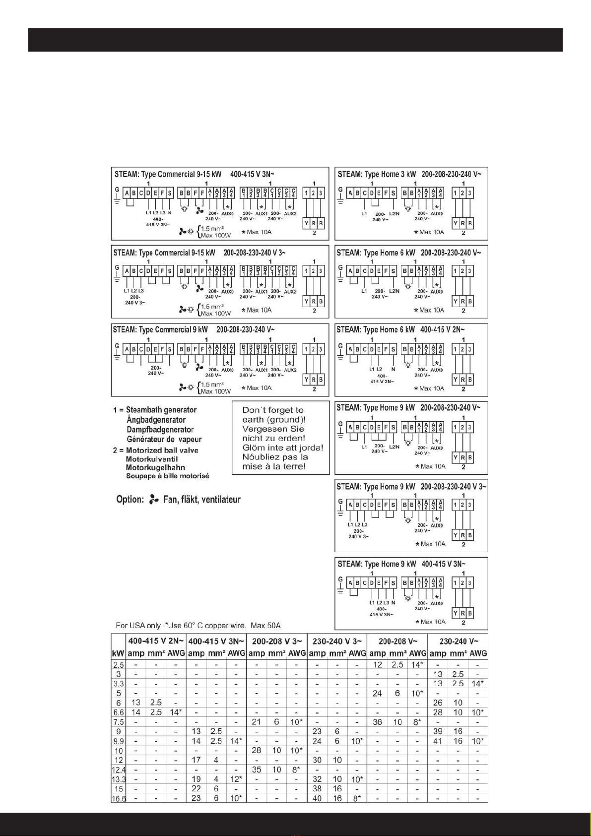
Plumbing installation – to be performed by a qualified plumbing installer. Electrical installation – to be performed by a qualified electrical
installer.
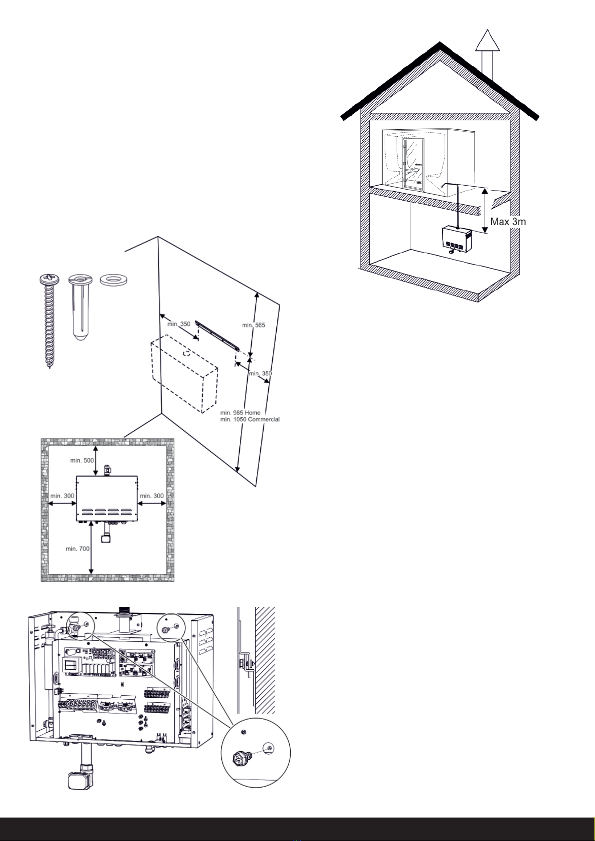
Fig. 1
G
Installation diagram of Steam Home and Commercial (Fig. 1)
A= Power supply line from electrical distribution board to steam
generator. It is an advantage to install a circuit breaker
between the distribution board and the steam generator. The
circuit breaker must always be switched on. If the current
is switched off before automatic emptying and fl ushing of
the tank has taken place (about 70 minutes after bathing is
completed), the operation stops, the tank will not be emptied
and the life of the steam generator will be reduced.
B= Wiring from control panel to steam generator.
C= Thermistor wire
D= Wiring to optional external on/off switch
E= E= Steam pipe
F= Drain pipe.
G= Incoming water.
H= The outlet vent must be connected to a ventilation duct to
take the air outdoors.
I= Supply air.
J= Pipe from safety valve.
K= Double swing check valve
1-6, see Fig. 12