The steam piping must not have any sharp bends.
Do not direct the steam jet against walls, seats or other
objects. Always keep a space of at least 80 cm clear in front
of the steam nozzle.
There must not be any water pockets in the steam piping
or ventilation ducts. IMPORTANT! There must not
be any kind of blockage in the steam piping (e.g. taps or
valves). The internal diameter of the steam piping must not
be reduced.
All steam rooms in continuous use for more than two hours
must have an air exchange rate of 10-20 m³ air per person
per hour.
The power supply for the steam generator must not be cut
o . Therefore avoid installing a power switch, etc. in the
power supply line.
The drain pipe must have a continuous fall all the way from
the steam generator to the drain.
The ambient temperature for the steam room and steam
generator must not exceed 35°C.
The sensor must be located as far from the steam jet as
possible.
Descale the steam generator regularly in accordance with
the instructions, refer to the heading Descaling. In areas
with hard water, exceeding 4°dH hardness, a water softener
or Tylö MACH 2020 water softener must be installed (Tylö
Item no. 9090 8025)
Clean the steam room regularly
NB! The steam generator drain must always lead to a drai-
nage channel outside the steam room. The steam generator
empties its tank 1 hour after each bath, the water will then be
80-85°C!.
WARNING! There is a jet of hot steam from the steam
nozzle. Never leave small children unattended.
This appliance can be used by children aged from 8 years
and above and persons with reduced physical, sensory or
mental capabilities or lack of experience and knowledge
if they have been given supervision or instruction concer-
ning use of the appliance in a safe way and understand the
hazards involved.
Children shall not play with the appliance.
Cleaning and user maintenance shall not be made by child-
ren without supervision.
IMPORTANT!
General
Plumbing installation to be performed by a quali ed plumbing installer. Electrical installation to be performed by a quali ed electrical
installer.
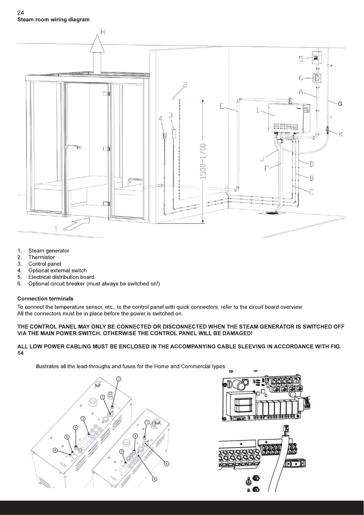
Fig. 1
(Fig. 1)
1-6, see Fig. 12