Tylo VA User manual

0905
Art nr 29000145 1
Installation and operating instructions with checklist for faults
Read through these instructions carefully before installation, and follow them in every respect to PLEASE KEEP THESE INSTRUCTIONS IN A SAFE
ensure flawless operation every time. After installation, please give these instructions to the PLACE - THEY CONTAIN IMPORTANT INFORMATION
owner or the person who will operate the steam room. ABOUT SERVICE AND MAINTENANCE PROCEDURES.
steam
VA, VB
USA

2
IMPORTANT!
•Do not make sharp bends or ”elbows” along the steam pipe.
•Do not direct the steam jet at a wall, seating or any other
object. There should be a free space of at least 70 cm (28")
in front of the steam nozzle.
•Do not allow sags or “water pockets” along the steam pipe
and/or the ventilation duct. IMPORTANT! There must not be
any type of obstruction along the steam line, such as a stop-
off valve or tap. The internal diameter of the steam pipe
must not be reduced.
•Ensure that steam rooms that are used continuously for
more than two hours at a time are ventilated by 10–20 cubic
metres of air per person and hour.
•The power supply to the steam generator via the feeder
cable must not be broken. For that reason, avoid switches,
etc., along the feeder cable.
•Make sure that the drainage pipe slopes all the way down to
the waste outlet.
•The ambient temperature outside the steam room and around
the steam generator must not exceed 35°C.
•Place the thermostat sensor as far away from the steam jet
as possible.
•De-scale the steam generator at regular intervals as
instructed. (Please read the section 'De-scaling' for further
details). In hard-water areas, where calcium levels exceed
5°dH, we recommend the installation of a water softener or
a Tylö automatic de-calcifier.
•Clean the steam room regularly. See the section on
“Cleaning the steam room” under Operating instructions.
•CAUTION! Stay at least 12" (30 cm) away from hot steam
escaping from steam outlet.
•IMPORTANT. The steam generator’s wastepipe must
always discharge into a drain outside the steam room itself.
The water is very hot.
General Information.
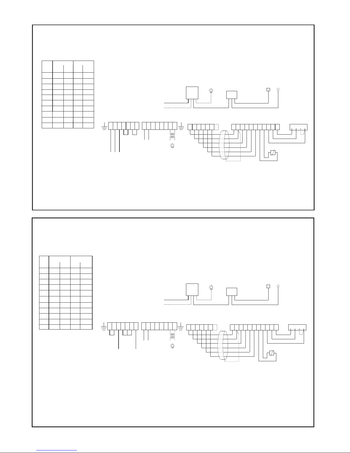
Fig. 1.
Examples of ventilation, electrical and plumbing
installation.
X = feeder cable from mains to steam generator. Do not
fit a switch along this cable. Where local regulations
require a switch to be fitted, this switch must always
be in the ON position. If the electrical supply is
interrupted before the automatic emptying and
flushing functions have occurred (approx. 80 min
after completion of bathing) these functions are
terminated without the reservoir being emptied. This
reduces the life expectancy of the steam generator.
Y = control cable from mains supply via control panel to
steam generator.
V = thermistor cable.
Z = cable to external on/off switch (if any).
D = steam pipe.
E = drainage pipe.
F = incoming water.
G = air inlet.
H = air outlet, leading out via a ventilation duct into the
open air.
The steam room.
The steam room should not have any other source of heat
than the steam generator. The ambient tempera-
ture around the steamroom and the steamgenerator
generator should not exceed 35°C (95°F). If there is a
sauna next to the steam room, the sauna must be well
insulated, and placed so as to give at least 10 cm (4")
free space between the outside walls of the sauna and
the steam room.
Location of the steam generator.
The steam generator must be installed by an authorised
electrician/plumber. The steam generator must be
permanently installed and secured against existing floor
or wall. It is to be located outside the steam room itself,
but as close to it as possible – no more than 15 m (50 ft)
away.
The steam generator must be placed in a dry and
ventilated space with a waste outlet, above, below or on
the same floor as the steam room, and concealed in a
cupboard, wardrobe, etc. (Never directly above a waste
outlet or in an aggressive environment).
The steam generator must be mounted horizontally, at a
suitable height above the floor to permit the drainage pipe
to slope towards the waste outlet. To achieve this, it may
sometimes be necessary to place the steam generator on
wall brackets, or a floorstand.
CC control panels.
Instructions: included with the control panel.
To be installed outside the steamroom, at any distance
from the steam room.
CC panels are electronically operated and are available in
the following models:
CC 10-3. Manual and automatic on/off. Maximum
3- hour running time, 10 hour pre-set.
CC 10-10. Manual and automatic on/off. Maximum
10- hour running time, 10 hour pre-set.
CC 50. Manual and automatic on/off. Maximum
3 or 12 hour running time, 10 hour pre-set.
CC 100. Manual and automatic on/off. Maximum
3 or 12 hour running time, 24 hour pre-set. Built-in weekly
timer.
CC 300. Manual and automatic on/off. Maximum
24 hour´s running time, 24 hour pre-set. Built-in weekly
timer.
Thermometer.
The thermometer in the steam room should be placed at
a height so that the temperature corresponds exactly to
the numbers in the names CC 50/ CC 100/ CC 300.
Temperature limit control.
Tylö steam generators are equipped with a built-in
temperature limit control. If the control is triggered off,
consult the checking and fault-finding list in this manual to
find the causes and a solution to the problem.
Note! The High temp limit control in a VA generator must
be reset by a Qualified electrician.
Main power switch.
On the bottom of the smaller steam generators is a power
switch, which should only be used if the unit is to be
disconnected for a long time.
The automatic emptying function ceases any time the
power is cut off.
Floors and drainage.
There must be a drain in the steam room, and the steam
room floor must slope towards the drain. The floor may be
covered with seamless vinyl flooring, quarry tiles, etc. The
requirements for sub-floor work, joining, etc., are the
same as for an ordinary shower.
PLEASE NOTE. Contact with steam and hot water may
cause plastic wallcovering/flooring close to the steam
head to become slightly discoloured.
Ventilation.
As a general rule, steam rooms which are in use for less
than two hours at a time require no special ventilation. In
order to ensure proper hygiene and trouble-free
operation, steam rooms which are in continuous use for
more than two hours at a time should be ventilated with
10–20 cubic metres of air per person and hour.
If there is a gap above the steam room, do not seal it. To
ventilate a cavity above the sauna, drill or cut at least one
ventilation hole (1000mm²) into the cavity through the wall
on which the sauna door is located.
The air inlet may be an opening placed low down on the
same wall as the door, or it may be a gap under the door.
The air outlet should be located high up on a wall or in
the ceiling, and as far away from the air inlet as possible.
However, the air outlet must not be located above the
door or directly above any of the seats. Connect the outlet
to a ventilation duct discharging into the open air. Use
existing ducting, if possible. The ventilation ducting must
be 100% steamtight and watertight, and made of
materials which will not deteriorate or corrode in the high
humidity. Do not allow the formation of “water pockets”,
caused by sags in the ducting, where condensed steam
may collect as water and cause a blockage. If a water
pocket is inevitable, install a trap to drain the condensed
water into the waste outlet.
The air outlet vent must be of sufficient size to allow the
evacuation of 10–20 cubic metres of air per person and
hour.
Mechanical ventilation. If the unassisted through-flow of
air is insufficient, due possibly to negative pressure in the
room supplying air to the steam room, a mechanical
exhaust fan must be installed and adjusted to extract a
minimum of 10 and a maximum of 20 cubic metres of air
per person and hour.
Steam generator functions.
All Tylö Model VA/VB Steam Generators incorporate
these features:
zStainless steel water reservoir zTubular heating
elements, resistant to rust and acid zAutomatic emptying
1 hour after the steam bath has been switched off
zAutomatic flush function rinses 4 times after emptying
z3-part output zElectronic water-level regulator
zElectronic water level control zSelf-cleaning, calcium-
repellent electrodes zContinuous steam production
zAlways the right output, regardless of quantity and
quality of water zBuilt-in safety valve zBuilt-in
temperature cut-off zBuilt-in filter zEquipped for remote-
control operation zAdjustable steam head zSplashproof
finish.
Automatic emptying.
This automatic function considerably reduces the build-up
of calcium carbonate and other deposits in the water
reservoir. Do not switch off any switches between the
mains supply and the steam generator until at least 80
minutes after the control panel timer has turned the
system off, because otherwise, the automatic emptying
and flushing of the water reservoir will not start.
WARNING. The water is very hot.
Automatic flushing with DIP
switch.
The steam generator is factory set to flush out part of the
water automatically after 4 hours. The steam generator
should, however, be emptied more frequently in areas
where the water is hard (5dH° or more than 100 ppm
calcium carbonate), or if it is used for more than four
hours per day. Set the required interval using the DIP
switches as shown (fig. 17).
WARNING. The water is very hot.
De-scaling.
Some of the limescale released from the water in the
steam generator is flushed out in the automatic emptying
and cleaning process; some, however, remains. The Tylö
Automatic De-calcifier (art no. 9090 7000) does not
remove limescale deposits as such, but modifies the ions
in such a way that more of the calcium is evacuated
during the flushing process. For this reason it is essential
to check that the automatic emptying function of the
steam generator has not been impaired by incorect
wiring. The reservoir must be emptied each time it has
been used.
To maximise serviceable life and reduce the need for the
manual removal of limescale deposits, we recommend
that steam generators for use in public facilities should be
connected to a water softener which removes calcium
from the water. This is particularly important if the
hardness of the water is greater than 5 degrees German.
(5 °dH, see table.)
The water softener must not generate any froth on the
water nor produce any harmful chemical reactions. If so,
the generator may indicate the wrong water level and
trigger the temperature cut-off. (Repeated activation may
result in the failure of the elements.)
The manual removal of limescale must be carried out at
regular intervals as specified in the table below.
For normal private use, there is little need for the manual
removal of limescale, unless the water is very hard. Even
so, it is advisable to de-scale the steam generator at least
once per year. This removes calcium and other deposits
that have become encrusted on the walls and elements of
the water reservoir.
Instructions for de-scaling Tylö Steam Generator
•Switch on the steam generator and let it run until the
water in the tank begins to boil.
•Switch the generator off and wait for approximately 5
minutes.
•Unscrew the capping nut from the 3-way connector on
top of the steam generator.
•Use a funnel to pour the de-scaling agent into the
tank via the 3-way connector.
•Screw the capping nut back in place on the 3-way
connector and leave the de-scaling agent to work.
•After approximately 1 hour the generator will
automatically empty and flush the tank. After this the
steam generator is once more ready for use.
Tylö Solvent is harmless, odourless, will not damage the
components in the steam generator and allows you to use
the steam generating function during the de-scaling
process. If you use any other type of de-scaling agent, do
not use the steam bath until after the de-scaling operation
has taken place.
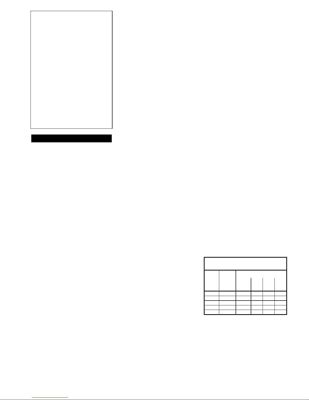
As the table shows, how often manual de-scaling needs
to be done depends on the quality of the water, the output
of the steam generator and the total operating time.
Operating time before de-scaling
(To reduce the need for manual removal of limescale we recommend
the use of softened water in public facilities)
Operating time for different water
hardnesses
Steam
generator
output kW
Amount of
de-scaling
agent
(1pack 80g)
Softened
0,01-1°dH
Soft
1-3°dH
Hard
3-8°dH
Very
hard
8-20°dH
2,0-2,5 2 pack 7000 2300 900 350
3,8-5 2 pack 3800 1300 500 190
5,6-7,5 2 pack 2600 900 300 130
7,5-9 2 pack 1700 600 200 90
10-13 2 pack 1300 400 160 70
(1-dH = 7.14 mg calcium / litre water)

3
How to make the most
of a steam bath.
Most people find that the most comfortable steam bathing
temperature is between 40 and 45°C. Use a bi-metallic
type of thermometer to check the temperature. Fix it on
the wall about 170 cm (67") above floor level, as far from
the steam jet as possible. There is no need for a
hygrometer. The relativity is always 100%.
•Shower and wash before starting your steam bath.
•Take a towel to sit on in the steam room.
•Relax and enjoy the soothing clouds of steam. You can
even listen to your favourite music while you do so. A
stereo unit with speakers specially made for steam bath
listening is available from Tylö’s range of accessories.
•Cool down now and again with a refreshing shower.
Alternate between the steam bath and the shower for
as long as you feel it is comfortable.
•After your last spell amongst the clouds of steam, you’ll
find a long, cool shower a real delight.
Let your body dry off naturally before putting your clothes
on. Relax, treat yourself to a cold drink and enjoy a
sensation of true well-being. Don’t get dressed until your
body has cooled down and your pores have closed once
again.
Cleaning the steam room.
Rinse seats and flooring with warm water (do not use a
high-pressure hose) each time the steam room has been
used. Wash the seats regularly with a mild soapy solution.
For daily disinfection, we recommend the Tylö Steam
Clean unit, which is fully automatic. Stubborn stains can
be removed with ethanol or petroleum (mineral) spirits.
Never use scouring powder, strong alkaline cleaners or
aggressive solvents on the seats and walls in the steam
room. Contact your Tylö representative if you are unsure
of how to remove stains.
It is important that the steam room floor is cleaned
thoroughly – right into the corners. Scrub clean with hot
water and a floor cleaner, which will remove grease and
grime.
Shower in the steam room.
We always recommend installing a shower in domestic
steam rooms. After all, a steam room also makes the best
shower room imaginable. And it is so pleasant to cool off
with an invigorating shower now and again during a
steam bath.
Fig. 2.
Measurements in millimetres: Tylö Model VA Steam
Generator.
Fig. 3.
Measurements in millimetres: Tylö Model VB Steam
Generator.
Required output in relation to cabin size:
Min/Max volume of the steam room
in cubic metres
kW
Lightweight walls
(tempered glass,
Elysée/Excellent rooms,
etc.)
Heavy walls
(tiles, concrete, stone,
etc.)
Steam
prod.
kg/h
with
ventilation
without
ventilation
with
ventilation
without
ventilation
2.5 - 0–2.5 - 0–1.5 3
3,8-4,5 0–4 0–5.5 0–2.5 0–3.5 5.5
5,6-6,0 3–8 4–15 2–5 2.5–8 8
6.6-7,5 3–9 4–17 2–6 2.5–9 9
9-9,9 6–16 13–24 4–10 7–16 12
10-13,2 14–22 22–30 8–15 14–20 16
Plumbing installation
To be carried out only by a qualified plumber.
Steam
generator
kW
No. of
steam
outlets
No. of
safety
valves
No. of
drainage
connections
No. of water
connections
2,2-13,2 1 1 1 1
Fig. 4.
Steam generator Model VA.
A = pipe joint.
B = capping nut.
C = steam outlet.
D = drainage connection. (safety valve)
E = water connection with integral filter.
F = cover for the electrodes.
Fig. 5.
Steam generator Model VB.
A = pipe joint.
B = capping nut.
C = steam outlet.
D = drainage connection. (safety valve)
E = water connection with integral filter.
Water connection: connect hot or cold water to pipe joint
1 on the steam generator. Hot water allows faster heating.
A flexible reinforced rubber hose (approx. 1 metre [3'3"]
long) is used to connect the copper piping (internal ∅at
least 12 mm [½"]) and the steam generator to prevent
noises in the system.
IMPORTANT! Flush the pipes thoroughly before
connecting the incoming water supply to the steam
generator.
Flushing the pipes prevents any metal filings or other
foreign bodies from getting into the steam generator’s
system.
Note:
In hard-water areas, where calcium levels exceed 5°dH,
we recommend the installation of a Tylö automatic de-
calcifier or a water softener to remove calcium from the
water. (Tylö accessory: Automatic Decalcifier art. no.
9090 7000). The water softener must not generate any
froth on the surface of the water or produce harmful
chemicals.
This is especially advisable for public installations.
Steam pipe: Connect the pipe joint to the steam outlet (2)
on the generator, with the capping nut upwards. Connect
a length of copper piping (internal diameter at least
12 mm [½"] ) to the steam outlet on the pipe joint. (C). The
steam pipe must slope down towards the steam room
and/or the steam generator – or towards both.
Fig. 6.
IMPORTANT! There must be no “water pockets” or sags
where steam may condense and collect as water along
the piping between the steam generator and the steam
room.
Fig. 7.
Plan for as few bends as possible in the steam pipe. Such
bends are to be gently curved, with a minimum radius of
5 cm (2"). Avoid any sharp “elbows” in the pipes.
IMPORTANT! There must not be any type of obstruction
along the steam line, such as a stop-off valve or tap. The
internal diameter of the steam pipe must not be reduced.
If the steam pipe is more than 3 metres (9'9") long, it
should be insulated along its full length. The distance
between any combustible material (e.g. wood) and an
uninsulated steam pipe must not be less than 10 mm
(0.4").
Figs. 8 and 9.
Fitting the steam head.
A = adjustable steam spout (use as required).
IMPORTANT
The steam head is to be fitted inside the steam room
between 5 and 40 cm (2–16") above floor level. In
principle, steam is released into the room lengthwise
under the seating. Do not direct the steam jet at walls,
seating or any other object. There should be at least
70 cm (28") free space in front of the steam head. In
steam rooms where there is no space under the seats,
the jet of steam should be directed diagonally upwards.
Set the spout so that the jet of steam is directed away
from the bathers. If the steam room is used by children or
people whose quick reactions are impaired, etc., a guard
should be fitted to prevent inadvertent contact with the jet
of steam issuing from the steam head.
Consult the assembly instructions accompanying the
steam room if the steam head is to be fitted in Tylö’s
steam room.
Drainage
Drainage from the steam generator. Fit the drainage
pipe (copper piping with minimum 12 mm internal
diameter) to connection number 3 on the steam
generator. The pipe must lead directly to the nearest drain
outside the steam room itself. The temperature of the
water that is drained off is approximately 95°C/200°F.
IMPORTANT! There must be no blockage of any type
(tap, faucet, etc.) along the drainage pipe.
Regardless of where the drainage head is located, it must
slope all the way from the steam generator to the waste
outlet. Under certain conditions, it may be necessary to
place the steam generator on wall brackets or a stand to
achieve the right angle.
Electrical installation.
To be carried out only by a qualified electrician.
The power feed to the steam generator is taken directly
from the mains fuse box. There must be no switches, etc.
along this feed line. See also under “Automatic emptying”.
Wiring diagrams 10 - 15 show wiring to one VA or VB
generator. Two steam generators can be linked to the
same steam room and controlled by a control panel; see
fig. 16.
Don’t forget to earth the unit!
Fig. 1 – steam bath.
1 = steam generator.
2 = thermistor (sensor).
3 = control panel CC 10/ CC 50/ CC 100/ CC 300.
4 = external on/off-switch (if any).
5 = mains fuse box.
Lighting.
Can be regulated by a control panel.
Maximum lighting voltage: 24 volts. Carefully seal all
holes made for wiring.
Connect the lighting according to the wiring diagram.
Placement of the thermistor
(sensor).
Place the sensor 150–170 cm above floor level inside the
steam room.
Important: Place the sensor as far from the steam jet as
possible. It must not be hit by the jet directly or indirectly.
The thermistor wire can be extended outside of the
steam room with a shielded low-voltage cable (2-core).
Shielded low-voltage cable
(LiYCY, 6-core).
The control cable between the CC 10/ CC 50/ CC 100/
CC 300 and steam generator must be a shielded low-
voltage cable (LiYCY, 6-core). Connect the shielded cable
to plinth 12 in the control panel.
Option: external on/off-switch
(momentary).
Can be placed at any distance from the steam bath.
Connected with a low-voltage cable to the CC 10/ CC 50/
CC 100/ CC 300 – see the wiring diagram. If there are
several external on/off switches, they should be parallel-
connected.
Connection to a central computer.
The control panel can also be connected to a central
computer, which gives a brief impulse (closure) between
plinths 19 and 20 in the CC 10/ CC 50/ CC 100/ CC 300
Connecting any extra equipment
The P5 and G6 connections are intended for connection
of mechanical ventilation, the Steam Fresh scent unit, the
Steam Clean disinfection unit, etc.

TEST 1.
Cause: The steam generator is wired up for the wrong
voltage.
WARNING! SEVERAL SUPPLY CIRCUITS. CHECK
THAT THERE IS NO CHARGE IN THE MACHINE
BEFORE DOING ANY MAINTENANCE WORK! Test for calcium deposits in the reservoir.
Solution: Check the voltage and the connection to the
generator – see diagram. Unscrew the capping nut at the top of the steam
generator. Lower a torch bulb, wired up to a battery, into
the hole. Inspect the illuminated tank through the hole. If
there is a layer of calcium carbonate extending more than
three centimetres above the bottom of the tank, the
reservoir has not been serviced as prescribed with regular
applications of a de-scaling agent.
Cause: The temperature limit control has been triggered,
see test 4.
Checking and fault-finding.
Solution: Check and remedy any faults on the steam pipe,
such as a blockage due to several sharp bends, water
pockets or greatly reduced internal diameter. The tank
may also be clogged with limescale; see above.
In the event of faulty operation, first check
the following:
•are the control panel and steam generator wired up in
accordance with the wiring diagram? The problem may also be that the emptying and flushing
systems are no longer operative. If there is a switch along
the feed cable to the steam generator, check that this has
not been used as an OFF switch after steam bathing. A
switch in the feed cable must not be switched off until at
least 80 minutes after the control panel has turned off the
system.
Cause: Flaw in the circuit board, control panel or
magnetic operated vent.
•is the steam generator correctly installed in accordance
with these instructions? Solution: Replace the faulty component.
•does the drainage pipe slope down properly towards
the waste outlet? Hot water runs from the steam head. Little
or no steam in the steam room.
•is the filter clogged? The filter is located at the point
where incoming water is fed into the generator. To
clean the filter, disconnect the feed pipe, remove the
filter and rinse it free from particles of calcium
carbonate and other deposits.
Cause: The solenoid valve for incoming water has stuck,
due to accumulated deposits of foreign bodies or an
electrical malfunction. See test 3.
Make sure that the automatic emptying function is
working, by placing a suitable vessel (capacity approx.
3 litres, 5 pints) under the drainage valve. Switch on the
steam generator and let it remain on for 15 minutes.
Switch off the generator in exactly the same way as you
always do when turning off the steam bath for the day.
Wait at least 80 minutes, and then check that the vessel
is full of water. If this is not the case, either the steam
generator has been incorrectly wired up, or the power to
the generator has been interrupted in some other way
along the cable from the electric supply to the generator,
or alternatively there is a fault in the drainage valve or the
circuit board.
Solution: Remove the valve and clean it, or rectify the
electrical malfunction.
•are there any sags along the steam pipe or along the
ventilation duct leading from the steam room? Cause: The solenoid valve is broken.
•are there any sharp bends in the steam pipe? (the
minimum permitted radius of bends is 50 mm, 2") Solution: Replace the valve.
Cause: Malfunction in the circuit board.
•If there is a tap on the water supply to the steam
generator, make sure this is not closed. Solution: Replace the circuit board.
Hot water comes out of the steam head in
spurts or in a slight, even flow mixed with
steam.
•does the construction and ventilation of the steam room
comply with Tylö’s instructions?
Checklist Cause: Small water pocket along the steam pipe.
with alternative causes of problems and suggested
actions. TEST 2.
Solution: Eliminate the water pocket.
Cause: The steam pipe is uninsulated along too great a
portion of its length. Temperature sensor test.
The steam room maintains the desired
temperature (40–50°C, 105–122°F), but no
steam is produced.
Soak a small towel in cold water. Hang the wet towel over
the thermostat sensor. If, within 20 minutes, the steam
generator has started to product steam continuously, the
equipment is not defective, but the thermostat sensor
(bulb) is located in an unsuitable position, or the
thermostat itself is set for too low a temperature. If steam
production does not begin, use the checklist to find out
the cause.
Solution: Insulate the steam pipe.
A continuous trickle of hot water from the
steam generator’s drainage pipe.
Cause: Insufficient ventilation in the steam room.
Solution: Increase ventilation. The ventilation is insufficient if
less than 10–20 cubic metres (13–28 cub. yd) of air per
person per hour is evacuated via the outlet vent. This
situation may occur if the outlet vent is not connected to
some form of mechanical extractor fan – or if the
ventilation duct is blocked by a water pocket.
Cause: The solenoid valve for automatic emptying has
stuck.
Solution: Switch off the steam generator. See what
happens again after an 80-minute pause. If the fault
persists, remove the solenoid valve for the automatic
emptying function and clean it. TEST 3.
Solenoid valve check.
Cause: The air coming into the steam room is too warm.
Loud noises in the feed pipes when the
solenoid valve opens or closes.
Use the control panel to switch off the steam generator. If
water continues to trickle out of the steam head more
than 10 minutes after the control panel has been switched
off, the cause is dirt in the solenoid valve. Remove and
clean the valve.
Solution: Reduce the intake air temperature to 35°C (95°F).
Cause: The ambient temperature is higher than 35°C
(95°F). Cause: The steam generator feed pipes are not
sufficiently secure.
Solution: Ensure that the ambient temperature does not
exceed 35°C (95°F). Solution: Fix the pipes securely to the wall with pipe clips.
Cause: The thermometer is faulty or wrongly placed. If the water stops running through the steam head within
10 minutes after the control panel has been switched off,
the cause is an electric fault (incorrect connection or
circuit board fault). Or, alternatively, excessive calcium
carbonate has accumulated in the reservoir. See test 1.
Cause: “Recoil” problems in the feed pipe (Pipe hammer).
Solution: The thermometer should be placed
approximately 170 cm (67") above floor level and as far
away from the steam jet as possible.
Solution: Replace a metre-long length of piping nearest
the steam generator with flexible piping, for example,
reinforced rubber hosing, which will withstand the
pressure.
The steam room requires an abnormally
long time to heat up. TEST 4.
Safety valve opens or temperature cut-off is
activated.
Cause: The generator is not powerful enough. See table. Steam pipe test if the safety valve or the
temperature cut-off is activated.
Solution: Replace the steam generator with one with a
higher heat output. Cause: The steam pipe is blocked; see test 4.
Solution: Remove the blockage. Disconnect the steam pipe from the steam generator.
Start the generator and let it remain on for about 1 hour. If
the safety valve or the temperature cut-off is not activated
during this test, there is a blockage along the steam pipe
which is preventing the passage of steam. Take the
necessary steps according to the information in the
checklist.
Cause: Excessive ventilation in the steam room. Cause: The internal diameter of the steam pipe is
considerably reduced. See test 4.
Solution: Reduce the ventilation to evacuate 10–20 cubic
metres (13–26 cub. yd) of air per person per hour. Solution: Replace the pipe or the pipe joint which is
causing the reduction (Internal diameter must be at least
12 mm, ½").
Cause: Blown fuse in the mains fuse box.
Solution: Replace the fuse.
Cause: The ambient temperature is lower than 15°C (59°F). Cause: Sharp bends (“elbows”) along the steam pipe.
See test 4.
Solution: Increase the ambient temperature or replace the
steam generator with a more powerful one.
Solution: Get rid of “elbows” in the pipe. Bends are to be
gently rounded (minimum radius 50 mm, 2").
Cause: Heating element is broken.
Solution: Replace reservoir. Cause: Large water pocket somewhere along the steam
pipe. See test 4.
Cause: The thermostat sensor is too close to the steam
jet. See test 2. If, during service, you wish to empty the tank,
disconnect the spade connector on the emptying
valve and connect the 230 volts’ mains supply
directly to the solenoid valve.
Solution: Adjust the steam pipe to eliminate the water
pocket.
Solution: Move the sensor or change the direction of the
steam jet. Cause: Excessive calcium carbonate deposits in the
steam generator’s reservoir. See test 1. IMPORTANT: This operation may only be carried
out by an authorised electrician.
Neither steam nor heat is generated in the
steam room. Solution: Replace the entire reservoir, including elements
and electrodes.
Cause: Blown fuse in the mains fuse box.
Erratic steam production right from the
start.
Solution: Replace the fuse.
Cause: The water is not reaching the steam generator.
Solution: Open the tap(s) connected to the piping to allow
incoming water to flow into the steam generator.
Cause: The thermostat sensor is wrongly placed in
relation to the steam jet. See test 2.
Cause: The control panel is incorrectly set. Solution: Move the sensor or alter the direction of the
steam jet.
Solution: Check the time and temperature on the control
panel. www.tylo.com
Cause: Calcium carbonate or other foreign bodies in the
filter.
In the event of any problems, please contact the retailer
where you purchased the equipment.
Cause: The filter is clogged.
Solution: Remove the filter which is placed in the
connection for incoming water. Clean off any metal filings
or other foreign bodies.
Solution: Remove and clean the filter. © This publication many not be reproduced, in part or in
whole, without the written permission of Tylö. Tylö reserves
the right to make changes in materials, construction and
design.
Cause: The solenoid valve for water supply has stuck.
Solution: Remove the solenoid valve and clean off any
metal filings or other foreign bodies.
Cause: Excessive calcium carbonate deposits in the
steam generator’s water reservoir. See test 1.
Solution: Replace the entire water reservoir, including
heating elements and electrodes.
4

So that the steam generator's automatic emptying and
rinsing functions are not rendered inoperative (which
may reduce the life of the generator), it is essential that
there is always a current in the power feed cable X. An
exception may, of course, be made when servicing the
steam generator.
The steam generator is always switched on and off from
the control panel or some other switch, timeclock etc.
which is connected to the cable marked Z.
ABkW
6-12 224 570
23
H
D
E
YF
G
Z
V
X
1
5
4
32
1700mm
1a
1b
Max 3m
90
485
A
B
70
415
10
130
445
Min. 500 Min. 500

4
6
9
7
8
5
A
F
AB
C
2
1
3
E
D
A
B
C
2
1
3
(1/2”) (3/4”)
E
D

10
11
1 = VA, VB
2 = thermistor (sensor)
3 = CC10, CC50, CC100, CC300
4 = external switch
1 = VA, VB
2 = thermistor (sensor)
3 = CC10, CC50, CC100, CC300
4 = external switch
STEAM: Type VA, 5 - 13,2 kW, Type VB 6 (5,6 / 7,5 kW)
208/240V3~
STEAM: Type VA, 5 - 13,2 kW, Type VB 6 (5,6 / 7,5 kW)
208 / 240 V~
6 x 0.2 mm² 2 x 0.5 mm²
3 x 0.2 mm²
3xTAB
3x*
3x*
3
42
1
TAB
208V3~ 240V3~
AWG AWG
kW Amp Amp
5
5.6
6.6
7.5
9.9
10
14 -
16
-
-16
21 18
-24
28
-
12 -
12
-
-12
10* 12
-10**
8** -
TAB
208 V~ 240 V~
AWG AWG
kW Amp Amp
2.5
3.8
5
5.6
-11
18 -
24 20
27 -
-14
12 -
10* 12
8** -
ABCD
L1
E
L2
F
L3
S
208/240 V 3~
11 12 13 14 15 17 11 12 13 14 15 16 17 18 19 20 21 3A 4B 5B 6B
11 134
2
GG
ABCDEFS
208/240 V~
11 12 13 14 15 17 11 12 13 14 15 16 17 18 19 20 21 3A 4B 5B 6B
11 134
2
GG
40 41 42 43 P
5G
6BB
110/208/240 V~
*
40 41 42 43 P
5G
6BB
110/208/240 V~
*
6 x 0.2 mm² 2 x 0.5 mm²
3 x 0.2 mm²
4xTAB
3x*
3
42
1
3x*
* AWG 16
** Use 60° C copper wire.
*** Use 75° C copper wire.
Not UL-listed for more than 48 Amps.
* AWG 16
** Use 60° C copper wire.
*** Use 75° C copper wire.
Not UL-listed for more than 48 Amps.
Max 24V
*
Max 24V
*
16
16
-
13.2 -32
8**
7.5
9.9
10
13.2
36 31
-41
48 -
-55
6** 8**
-6**
6** -
-6***
6.6 -28- 8**
--
5.6 16 12
618
10** --
926 10**
12 35 6**
-
-
6
30
8** --
945 6** --

12
1=VB
2 = thermistor (sensor)
3 = CC10, CC50, CC100, CC300
4 = external switch
STEAM: Type VB 2/4 (2.5 kW)
240 V~
6 x 0.2 mm² 2 x 0.5 mm²
3 x 0.2 mm²
3xTAB
3 x 1.5mm²
3
42
1
A40
B41
C42
D43 P
5G
6BB 11 12 13 14 15 17 11 12 13 14 15 16 17 18 19 20 21 3A 4B 5B 6B
11 134
2
GG
*
240 V~
Max 24V
*
16
TAB
Amp
240 V~
Awg
2.5 11 14
kW
* AWG 16
** Use 60° C copper wire.
*** Use 75° C copper wire.
Not UL-listed for more than 48 Amps.
14
1=VB
2 = thermistor (sensor)
3 = CC10, CC50, CC100, CC300
4 = external switch
STEAM: Type VB 2/4 (3,8 / 5,0 kW)
208 / 240 V~
TAB
208 V~
Amp Awg
3.8 18 12
3x*
3x*
6 x 0.2 mm² 2 x 0.5 mm²
3 x 0.2 mm²
3xTAB
3
42
1
240 V~
5-
--
20 12
kW Amp Awg
-
* AWG 16
** Use 60° C copper wire.
*** Use 75° C copper wire.
Not UL-listed for more than 48 Amps.
A40
B41
C42
D43 P
5G
6BB 11 12 13 14 15 17 11 12 13 14 15 16 17 18 19 20 21 3A 4B 5B 6B
11 134
2
GG
110/208/240 V~
208/240 V~
Max 24V
*
16
*
15
1 = VA (2x), VB (2x)
2 = thermistor (sensor)
3 = CC10, CC50, CC100, CC300
4 = external switch
STEAM: Type VA (2x), Type VB (2x)
6 x 0.2 mm² (AWG 24)6 x 0.2 mm² (AWG 24) 2 x 0.5 mm² (AWG 20)
3 x 0.2 mm² (AWG 24)
}
3/4/5xTAB
3xAWG16
3
42
11
16
DIP-switch Function
2 Hour NO TIMER
1 Hour 6 Hour
4 Hour TEST
=Switch position at the
DIP-switch.
DIP-switch Function
13
1=VB
2 = thermistor (sensor)
3 = CC10, CC50, CC100, CC300
4 = external switch
STEAM: Type VB 2/4 (2,2 kW) 110 / 120 V~
3x*
3x*
6 x 0.2 mm² 2 x 0.5 mm²
3 x 0.2 mm²
3xTAB
3
42
1
TAB
110-120 V~
Amp Awg
2.2 20 12
kW
* AWG 16
** Use 60° C copper wire.
*** Use 75° C copper wire.
Not UL-listed for more than 48 Amps.
A40
B41
C42
D43 P
5G
6BB 11 12 13 14 15 17 11 12 13 14 15 16 17 18 19 20 21 3A 4B 5B 6B
11 134
2
GG
110/120 V~
110/120 V~
Max 24V
*
16
*
This manual suits for next models
1
Table of contents
Other Tylo Iron manuals