1 Important notes
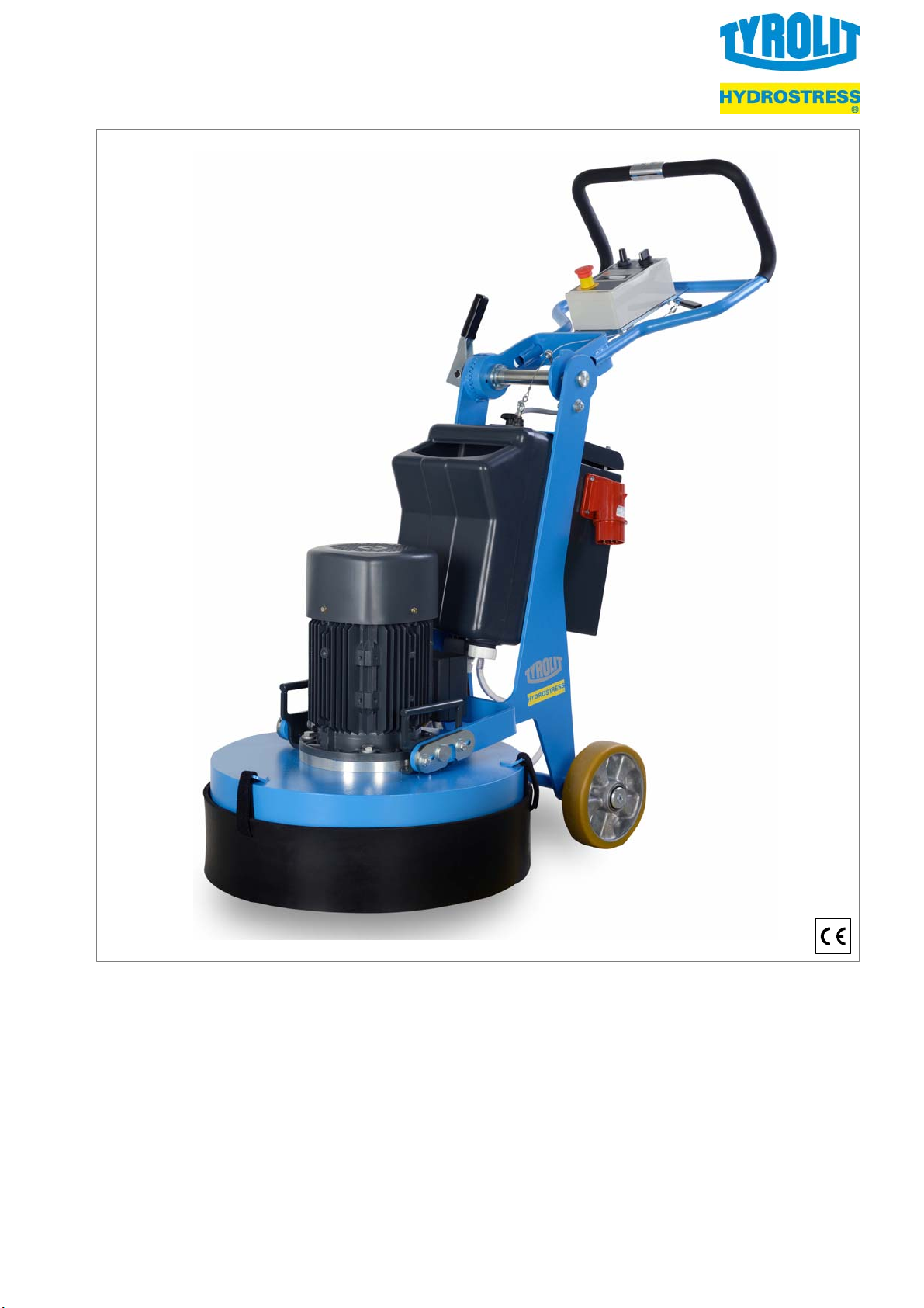
EN Floor grinding machine FGE 530
5
1 Important notes
The machine may be used only with the accessories
supplied by the manufacturer for stripping, wet and
dry grinding of floor surfaces such as:
—cement
—screeds
—synthetic resin screed / asphalt
—natural stone floors
—remnants of adhesive or filling compound
—floor remnants (e.g. foam backing)
Any other use of the machine can lead to dangerous
situations and is prohibited!
To ensure correct use of the machine, follow the in
structions in the operating manual, paying particular
attention to any warnings and instructions relating to
operation and maintenance!
Before using the machine, the opera
ting personnel must carefully read and
understand this operating manual!
Keep this operating manual close at
hand for easy reference!
Read and observe documents and operating manuals
provided by suppliers!
If the machine is on loan to other parties, the opera
ting manual needs to be provided with the machine
and its importance must be made clear!
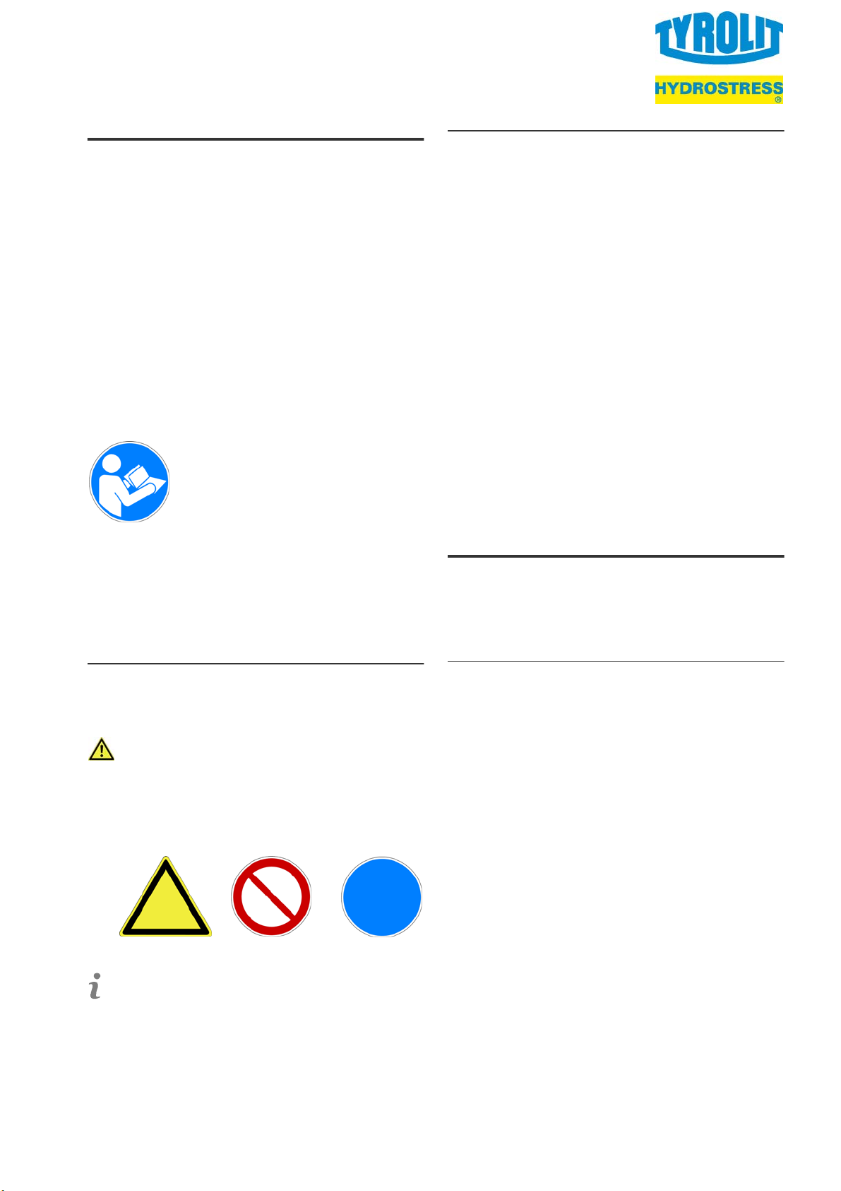
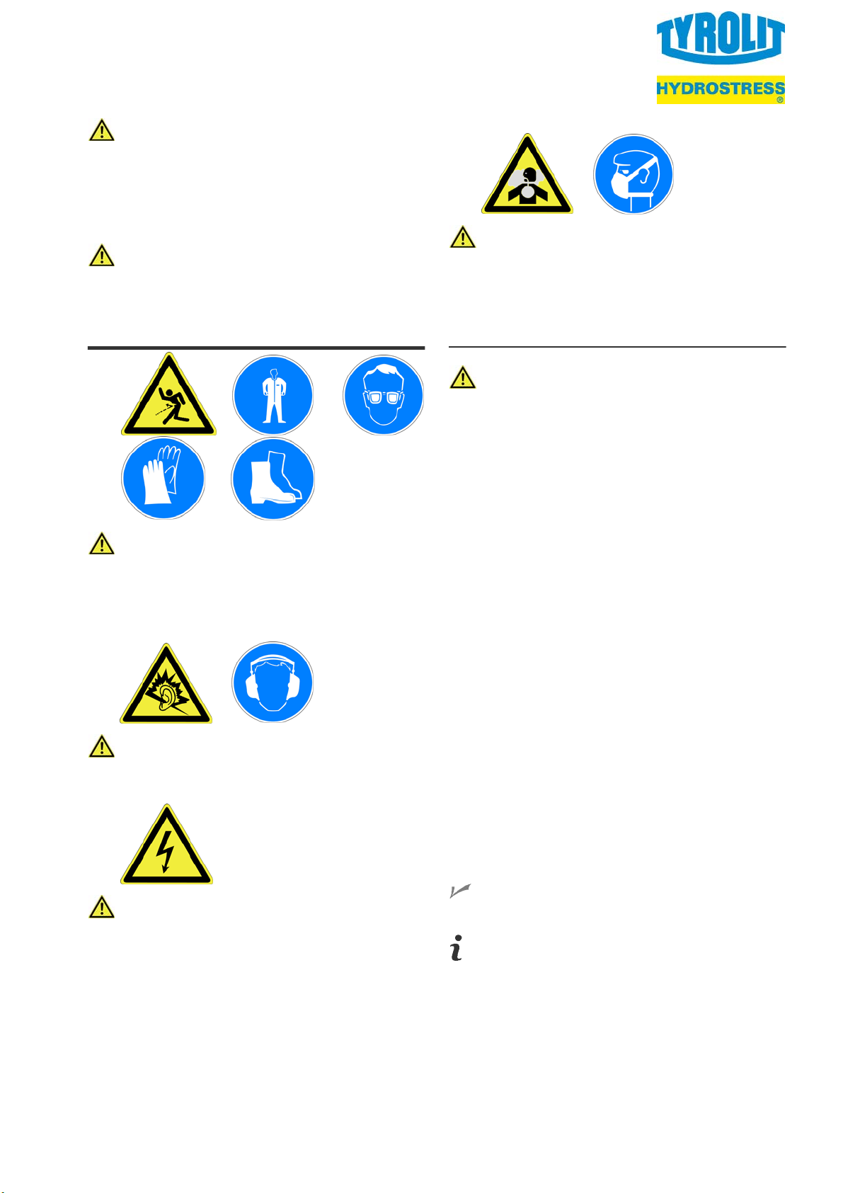
1.1 Symbols used
The following symbols are used in this
documentation:
Safety instructions
This symbol indicates warnings, prohibitions and
instructions regarding potential hazards. These
instructions must be obeyed and closely
observed.
Some safety instructions are accompanied by
appropriate symbols.
Additional information
This symbol indicates additional information.
1.2 Liability and warranty
TYROLIT Hydrostress AG
All rights, including those pertaining to translation, lie
with TYROLIT Hydrostress AG.
Liability or warranty is excluded if:
—The instructions in the operating manual have not
been observed.
—The machine or its attachments were improperly
operated.
—The maintenance was carried out inadequately or
incorrectly.
—Specified spare parts were not used.
—The protective guards were not used, have been
altered or were removed.
—The specified power supply ratings and surroun
ding conditions have not been observed.
The manufacturer is not liable for any damage that
may result if the user makes any changes to the ma
chine without the manufacturer's permission. Any
such actions will also void the warranty.
2 Safety
This chapter contains a summary of the most impor
tant information on safety when handling the ma
chine.
2.1 Accident prevention and safety
The following instructions comply with legislation, di
rectives, and publications including:
—EC Machinery Directive
—EC General Product Safety Directive
—Law governing technical materials
—Law governing equipment safety
—Law governing product liability
This operating manual is intended for operators and
tool setters, as well as for the personnel that service,
maintain and repair the machine. Together with all
the technical documentation, it is intended to help
—avoid hazardous situations
—use the machine for its intended applications
—avoid downtime and repair costs
—maintain the function of the machine
—extend the service life of the machine.
The manufacturer and owner of the machine must
respect the contents and regulations of the EC direc
tives. The effectiveness of any measure ultimately
depends on how well all parties, i.e. the manufactu
rer, the owner and the machine operators, work toge
ther to uphold safety standards.
Warning Prohibition Direction