TYROLIT Hydrostress WSE1621 User manual

Translation of the original instructions
10999155 en / 04.12.2018
Index 000
OPERATING INSTRUCTIONS
WSE1621 WALL SAW

Page 2
WSE1621 Wall saw
TYROLIT Hydrostress AG
Witzbergstrasse 18
CH-8330 Pfäkon
Switzerland
Tel. 0041 (0) 44 952 18 18
Fax 0041 (0) 44 952 18 00
Congratulations!
You have decided to purchase a tried-and-tested TYROLIT Hydrostress unit and have thus
acquired a highly sophisticated and reliable state-of-the-art device. Only genuine TYROLIT
Hydrostress replacement parts can guarantee quality and interchangeability. If maintenance
work is neglected or carried out inexpertly, we will be unable to honour our warranty obliga-
tions. All repairs must be carried out by trained personnel only.
Our after-sales service is available to help ensure that your TYROLIT Hydrostress units remain in
perfect working order.
We hope that working with your TYROLIT unit will be a satisfying and fault-free experience.
TYROLIT Hydrostress
Copyright © TYROLIT Hydrostress

TYROLIT Hydrostress AG
Page 3
WSE1621 Wall saw
Table of contents
Page
1. Safety ........................................................................... 5
1.1 Generally applicable safety instructions ..................................... 5
1.2 Signs on the equipment .................................................... 6
1.3 Action in an emergency .................................................... 6
2. Description ..................................................................... 7
2.1 Wall saw system ............................................................ 7
2.2 Intended use ............................................................... 7
2.3 Wall saw system components ............................................... 7
2.4 Main components of the wall saw head ..................................... 8
3. Mounting / removal ............................................................. 9
3.1 Placing the wall saw on the guide rail ....................................... 9
3.2 Adjusting the guide rollers.................................................. 10
3.3 Mounting the motor........................................................ 11
3.4 Securing the motor......................................................... 12
3.5 Removing the motor ....................................................... 13
3.6 Mounting the saw blade .................................................... 14
3.7 Mounting the saw blade unit ............................................... 17
3.8 Removing the saw blade unit ............................................... 18
3.9 Blade guard ................................................................ 19
3.10 Connecting the control unit ................................................ 20
4. Operation ....................................................................... 24
4.1 Overview of controls ....................................................... 24
4.2 Starting the wall saw ....................................................... 26
4.3 Changing the frequency of the remote controller............................ 27
4.4 Selecting the mains power supply .......................................... 28
4.5 Selecting the tool station ................................................... 29
4.6 Adjusting the feed.......................................................... 30
4.7 Manually adjusting the feed speed.......................................... 31
4.8 Locking the feed ........................................................... 31
4.9 Changing the direction of rotation of the main motor. . . . . . . . . . . . . . . . . . . . . . . . 32
4.10 Switching o the wall saw .................................................. 33
4.11 Deactivating the EMERGENCY STOP function ................................ 34
4.12 After nishing work. . . . . . . . . . . . . . . . . . . . . . . . . . . . . . . . . . . . . . . . . . . . . . . . . . . . . . . . . 35
4.13 Responding to displays ..................................................... 36
4.14 Power displays ............................................................. 37
TYROLIT Hydrostress AG
Page 4
WSE1621 Wall saw
5. Servicing and maintenance ..................................................... 39
5.1 Cleaning ................................................................... 40
5.2 Replacing the guide rollers ................................................. 41
5.3 Lubricating the lock unit ................................................... 41
5.4 Changing the gear oil ...................................................... 42
5.5 Recycling waste ............................................................ 42
6. Malfunctions .................................................................... 43
7. Technical data .................................................................. 44
7.1 Dimensions ................................................................ 44
7.2 Weights .................................................................... 45
7.3 Design ..................................................................... 45
7.4 Saw blades ................................................................. 45
7.5 Overcut table............................................................... 46
7.6 Saw blade feed depths ..................................................... 47
7.7 Saw blade drive motor...................................................... 47
7.8 Feed motor, travel .......................................................... 47
7.9 Feed motor, swivel. . . . . . . . . . . . . . . . . . . . . . . . . . . . . . . . . . . . . . . . . . . . . . . . . . . . . . . . . . 47
7.10 Noises ..................................................................... 48
7.11 Water ...................................................................... 48
7.12 Lubricants and uids ....................................................... 48
7.13 Electrical data .............................................................. 48
7.14 Recommended ambient temperature ....................................... 49
7.15 Remote controller .......................................................... 49
7.16 Name plate................................................................. 49
8. EC Declaration of Conformity ................................................... 50

TYROLIT Hydrostress AG
Page 5
WSE1621 Wall saw
Safety
Generally safety instructions
These instructions are just one part of the documentation which is supplied together with the
wall saw. These instructions go together with the "Safety Manual/System Description for Wall
Saws" to form a complete set of documentation.
DANGER
Failure to comply with the safety instructions in the "Safety Manual/System Handbook" and the
operating instructions may result in serious injury or even death.
XPlease ensure that the "Safety Manual/System Description for Wall Saws" and the operating
instructions have been read and understood in full.
DANGER
Laceration from the saw blade.
XAlways wear protective gloves when working on the wall saw, particularly when working on
the saw blade.
XAlways use the blade guard when operating the wall saw.
DANGER
Serious injury or material damage as a result of uncontrolled movements of the wall saw.
XNever connect or disconnect cables when the wall saw is running.
DANGER
Death or serious injury can be caused by sudden start-up of the machine.
XBefore switching on the system, ensure that no other persons are present in the danger areas.
XOn leaving the system, switch it o and ensure that it cannot be switched on again.
DANGER
Death or serious injury as a result of the sawing machine continuing to run after an accident.
XEnsure that the EMERGENCY STOP button can be reached quickly.
DANGER
Electric shock from live cables and connectors.
XSwitch o the WSE1621 Wall saw before connecting or disconnecting cables.
XEnsure the power supply is earthed and tted with an AC/DC sensitive residual current
circuit breaker (FI type B) with a maximum residual current of 30mA.
DANGER
Risk of re due to incorrect mains voltage.
XMake sure the mains voltage and mains frequency correspond to the mains settings of the
WSE1621 Wall saw.
1
1.1

TYROLIT Hydrostress AG
Page 6
WSE1621 Wall saw
Signs on the machine
Torque information / name plate
Signs on the machine
What to do in an emergency
XPress the EMERGENCY STOP button on the remote controller.
The LED indicator light ashes quickly when the EMERGENCY STOP function is activated on the
radio remote controller.
EMERGENCY STOP
1.2
1.3

TYROLIT Hydrostress AG
Page 7
WSE1621 Wall saw
Description
Wall saw system
The design and function of the wall saw systems are described in the “Safety Manual/System
Description for Wall Saws”.
Intended use
Transportable wall saw for use on construction sites, for cutting (reinforced) concrete, stone and
masonry. Only for industrial use.
Not suitable for use in potentially explosive atmospheres.
Wall saw system components
Wall saw system
1 WSE1621P Control unit 8 Guide rail
2 Mains cable with connector 9 Wall saw head
3 Electric cable for feed motor 10 Drive motor
4 Electric cable for main motor 11 Diamond saw blade
5 Water hose 12 Blade guard
6 Rail stopper 13 Radio remote controller
7 Rotating rail support
2
2.1
2.2
2.3

TYROLIT Hydrostress AG
Page 8
WSE1621 Wall saw
Main components of the wall saw head
Wall saw head components
Components
1 Guide roller 11 Saw blade mount
2 Undercarriage 12 Motor fuse
3 Grip for motor 13 Quick-release ange
4 Saw blade drive motor 14 Casing
5 Connector for feed motors 15 Housing cover (oil change)
6 Water connection 16 Swivel arm
7 Connector for saw blade drive motor 17 Feed motor, swivel
8 Grip / lock grip 18 Blade guard uptake
9 Grip for motor 19 Water control valve
10 Feed motor, travel 20 Lock unit
2.4
2.4.1

TYROLIT Hydrostress AG
Page 9
WSE1621 Wall saw
Mounting / removal
Placing the wall saw on the guide rail
Mounting the wall saw
If the swivelling handle fails to engage or the wall saw sits too loosely on the guide rail:
adjust the guide rollers.
3
3.1

TYROLIT Hydrostress AG
Page 10
WSE1621 Wall saw
Adjusting the guide rollers
9Tool
Fork wrench Size 24
TYROLIT No. 973773
Allen key Size6
TYROLIT No. 973792
Adjusting the guide rollers
The guide rollers have been set correctly if they can no longer be turned by hand.
In order for the machine to travel parallel to the rail, both guide rollers must be adjusted identi-
cally.
3.2

TYROLIT Hydrostress AG
Page 11
WSE1621 Wall saw
Mounting the motor
The motor can be mounted without using any tools.
To enable the motor to engage with the coupling, you must be able to turn the blade hub.
Thisis only possible if the diamond saw blade (1) or the quick-release ange (2) is mounted.
Mounting the motor
1 Diamond saw blade
2 Quick-release ange
3.3

TYROLIT Hydrostress AG
Page 12
WSE1621 Wall saw
Securing the motor
DANGER
Risk of injury if the motor falls!
XWhen the motor has been mounted, it must be secured.
Securing the motor
3.4

TYROLIT Hydrostress AG
Page 13
WSE1621 Wall saw
Removing the motor
The motor can be removed without using any tools.
Removing the motor
3.5

TYROLIT Hydrostress AG
Page 14
WSE1621 Wall saw
Mounting the saw blade
DANGER
Death or serious injury can be caused by an escaping saw blade.
XOnly use original screws and bolts from TYROLIT Hydrostress AG.
DANGER
Serious injury can be caused by sudden start-up of the saw blade.
XSwitch o the wall saw before working on the saw blade.
XIsolate the wall saw from the mains supply.
Diamond saw blades can be mounted on the WS1621 wall saw using uptake drill holes of
Ø60mm.
Saw blade unit
The saw blade unit consists of the TYROLIT quick-release ange and the saw blade.
The direction of rotation of the saw blade must match the direction of rotation of the machine.
Correct alignment: Countersinking of the xing holes against the blade cover.
Saw blade unit
A Saw blade unit for normal cutting 1 Flange
B Saw blade unit for ush cutting 2 Cap
3 Saw blade
3.6
3.6.1

TYROLIT Hydrostress AG
Page 15
WSE1621 Wall saw
Saw blade xing for normal cutting
DANGER
Death or serious injury can be caused by a ying saw blade!
XAlways secure the diamond saw blade by using 6 original TYROLIT countersunk screws
and 2 blade cover screws.
XTighten the countersunk screws to a torque of 10 Nm.
XTighten the blade cover screws to a torque of 50 Nm.
XTighten the central screw to a torque of 60 Nm.
Saw blade diameters
Ø 650 mm / Ø 825 mm / Ø 1025 mm / Ø 1200 mm / Ø 1600 mm
9Tool
Fork wrench Size19
TYROLIT No. 973784
Allen key Size5
TYROLIT No. 973791
Saw blade xing for normal cutting
3.6.2

TYROLIT Hydrostress AG
Page 16
WSE1621 Wall saw
Saw blade xing for ush cutting
DANGER
Death or serious injury can be caused by a ying saw blade!
XAlways secure the diamond saw blade by using 6 original TYROLIT countersunk screws.
XTighten the countersunk screws to a torque of 10 Nm.
XTighten the central screw to a torque of 60 Nm.
Saw blade diameters
Ø 650 mm / Ø 825 mm / Ø 1025 mm / Ø 1200 mm / Ø 1600 mm
9Tool
Allen key TYROLIT No. 973791 (size 5)
Saw blade xing for ush cutting
3.6.3

TYROLIT Hydrostress AG
Page 17
WSE1621 Wall saw
Mounting the saw blade unit
DANGER
Death or serious injury can be caused by a ying saw blade!
XCheck whether the sleeve and central screw are countersunk.
XTighten the central screw to a torque of 60 Nm.
9Tool
Allen key TYROLIT No. 10980265
Torque wrench TYROLIT No. 10982724
Mounting the saw blade unit
3.7

TYROLIT Hydrostress AG
Page 18
WSE1621 Wall saw
Removing the saw blade unit
WARNING
Risk of injury if the saw blade falls!
XLift out the saw blade unit to the top when removing it.
Removing the saw blade unit
Remove the saw blade unit in reverse order to the mounting/assembly process.
3.8
3.8.1

TYROLIT Hydrostress AG
Page 19
WSE1621 Wall saw
Blade guard
Mounting the blade guard
XMount the blade guard according to the instruction leaet.
Mounting/removing the blade guard
Removing the blade guard
Remove the blade guard in the reverse order to the mounting/assembly process.
3.9
3.9.1
3.9.2

TYROLIT Hydrostress AG
Page 20
WSE1621 Wall saw
Connecting the control unit
Establishing the mains, motor and water supply
Before starting to use the system, please read the operating instructions supplied with the
WSE1621 Control unit.
Mains
9Connectors/plugs are clean
9Cables are undamaged
9The power supply is earthed and tted with an AC/DC sensitive residual current circuit
breaker (FI type B; max. residual current 30mA)
9Sucient cable cross-sections: up to 50m long 4 x 4mm2, more than 50m long 4 x 6mm2
Connecting motors
9Connectors are clean
9Cables are undamaged
Control unit connections
M Cutting tool drive motor
M v Feed motor
3.10
3.10.1
3.10.2
3.10.3
Other manuals for WSE1621
1
Table of contents
Other TYROLIT Hydrostress Power Tools manuals

TYROLIT Hydrostress
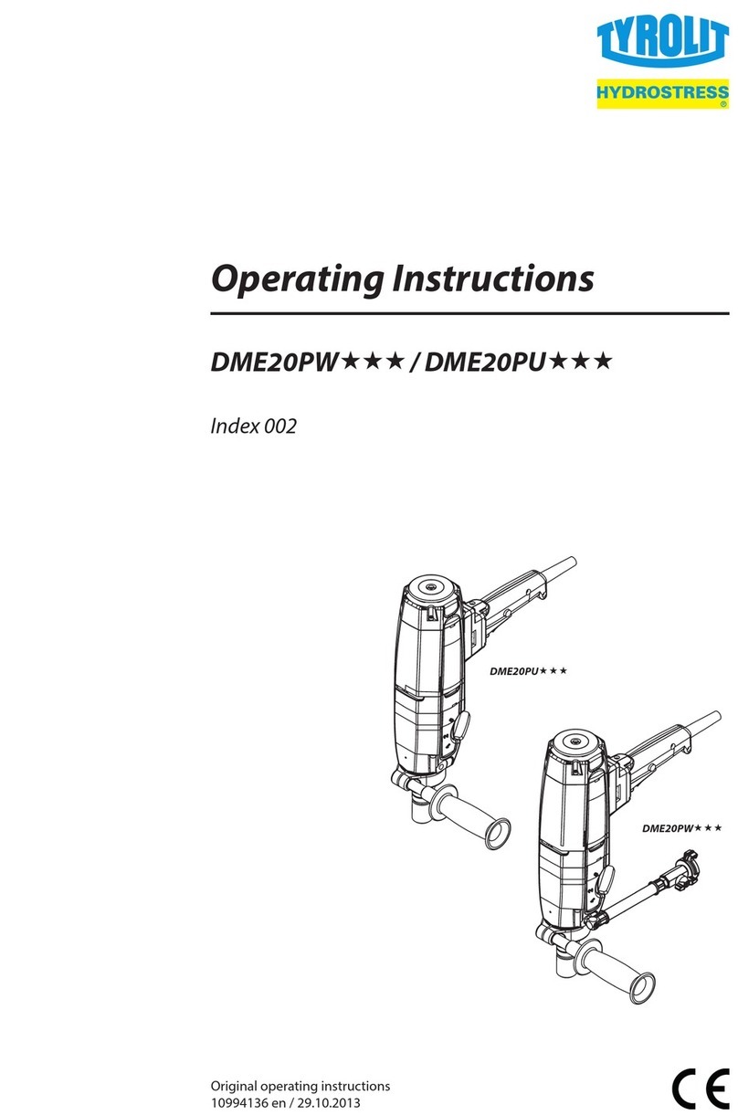
TYROLIT Hydrostress DME38UW User manual

TYROLIT Hydrostress
TYROLIT Hydrostress DME20PW Series User manual

TYROLIT Hydrostress
TYROLIT Hydrostress DME24MW Series User manual

TYROLIT Hydrostress
TYROLIT Hydrostress HGE125 User manual

TYROLIT Hydrostress
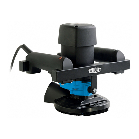
TYROLIT Hydrostress HCE150 User manual

TYROLIT Hydrostress
TYROLIT Hydrostress / DME24UW Series User manual

TYROLIT Hydrostress
TYROLIT Hydrostress DME19DPP Manual