manuals.online logo
Brands
  1. Home
  2. •
  3. Brands
  4. •
  5. U-Line
  6. •
  7. Refrigerator
  8. •
  9. U-Line U-2218WCINT-00A Installation manual

U-Line U-2218WCINT-00A Installation manual

USER GUIDE & SERVICE MANUAL
Model: U-2218WCINT-00A
USER GUIDE & SERVICE MANUAL
Table of Contents
Click on any section below to jump directly there
Installation
Integrated Panel Dimensions
Integrated Panel Installation
Integrated Grille Dimensions
Grille / Plinth Installation
USER GUIDE
Introduction
WELCOME TO U-LINE
Congratulations on your U-Line purchase. Your product comes from a company with over ve decades of premium modular ice
making, refrigeration, and wine preservation experience. U-Line creates products focused on functionality, style, and inspired
innovations — paying close attention to even the smallest details. Applications include residential, outdoor, ADA height
compliant, marine, and commercial. Complete product categories include Beverage Centers, Wine Refrigerators, Ice Machines,
Refrigerators, Freezers, and Dispensers.
Our advanced refrigeration systems, large and exible capacities, and Built-In to Stand Out®clean integrated look allow you
to preserve the right product, in the right place, at the right temperature. Since 2014, U-Line has been part of the Middleby
family of brands. All products are designed, engineered, and assembled in Milwaukee, Wisconsin, USA, and select products
are available worldwide. U-Line - RIGHT PRODUCT. RIGHT PLACE. RIGHT TEMPERATURE®.
PRODUCT INFORMATION
Looking for additional information on your product? User Guides, Spec Sheets, CAD Drawings, Compliance Documentation,
and Product Warranty information are all available for reference and download at u-line.com.
PROPERTY DAMAGE / INJURY CONCERNS
In the unlikely event property damage or personal injury is suspected related to a U-Line product, please take the following
steps:
1. U-Line Customer Care must be contacted immediately at +1.414.354.0300.
2. Service or repairs performed on the unit without prior written approval from U-Line is not permitted. If the unit has been
altered or repaired in the eld without prior written approval from U-Line, claims will not be eligible.
GENERAL INQUIRIES
U-Line Corporation
8900 N. 55th Street
Milwaukee, Wisconsin 53223 USA
Monday - Friday 8:00 am to 4:30 pm CST
T: +1.414.354.0300
Email: sales@u-line.com
u-line.com
CONNECT WITH US
SERVICE & PARTS ASSISTANCE
Monday - Friday 8:00 am to 4:30 pm CST
T: +1.800.779.2547
Service Email: onlineservice@u-line.com
Parts Email: onlineparts@u-line.com
Designed, engineered and assembled in WI, USA
3
USER GUIDE
Integrated Panel Dimensions 1
SAFETY • INSTALLATION & INTEGRATION • OPERATING INSTRUCTIONS • MAINTENANCE • SERVICE
Integrated Panel Dimensions
Metric measurements rounded and optimized.
INTEGRATED FRAME
NOTICE
Due to differences in surrounding cabinetry the
panel may not perfectly align with door. The
procedure below is designed to provide a
finished integrated panel that seamlessly
integrates with surrounding cabinetry.
Panel Preparation
A full integrated door panel completely covers the door
frame and provides a built-in appearance.
NOTICE
The door panel must not weigh more than 20 lbs
(10 kg).
It is important to ensure that all drilled holes are
drilled to the correct depth in order to avoid
splits in the wood when hardware is installed.
1. Cut the panels to the dimensions listed in the diagram
below.
2. Optional: Stain or finish panel to desired stain or color.
Be sure to closely follow the instructions provided by
the manufacturer.
3. Optional: Install handles and hardware.
NOTICE
When applying an integrated frame to a unit,
ensure that both sides are finished in order to
prevent warping. In some frame installations,
the panel may be visible through the glass while
the door is open.
Integrated Frame Dimensions
BACK SURFACE MUST HAVE AMPLE FLAT SURFACE
TO MOUNT OVERLAY FRAME FLAT AND WITHOUT
INTERFERENCE
17-5/8"
(445 mm)
3/4"
(20 mm)
2-3/4" MIN
(70 mm MIN)
30"
(762 mm)
Integrated Frame
4
USER GUIDE
Integrated Panel Dimensions 2
SAFETY • INSTALLATION & INTEGRATION • OPERATING INSTRUCTIONS • MAINTENANCE • SERVICE
HANDLELESS INTEGRATED FRAME
The following procedure is designed to provide a finished,
handleless frame for an 18" (45 mm) door that seamlessly
integrates with its surrounding cabinetry.
NOTE: Many cabinet manufacturers provide a ready
solution for a handleless, integrated design that can be
easily applied to your U-Line 3000 Series model. Consult
your cabinet manufacturer for applicable design and
installation details. The cabinet manufacturer’s solution to
this design and integration detail will often result in an
integrated frame solution wherein the size of the frame
may result in a height dimension taller than what we
specify. This can be achieved provided the additional
height is positioned above the appliance door.
NOTICE
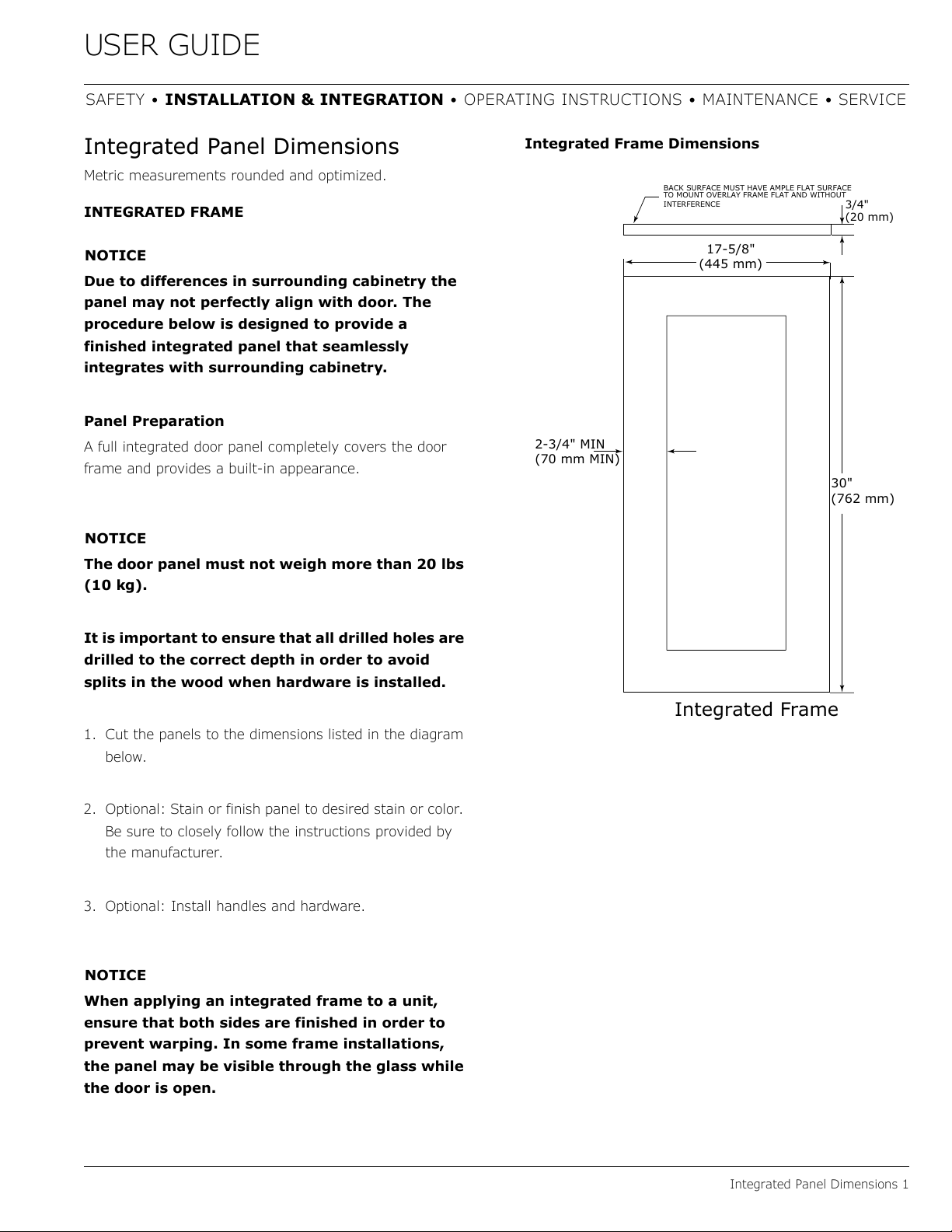
The integrated frame aligns with the
surrounding cabinetry and, due to differences in
cabinetry, may not align perfectly with the door.
The appliance will need up to 34-1/2" (876 mm)
to the underside of the counter to leave room for
leveling adjustments.
A single prepared frame with insert must not
weigh more than 20 lbs (10 kg).
Integrated Frame Preparation
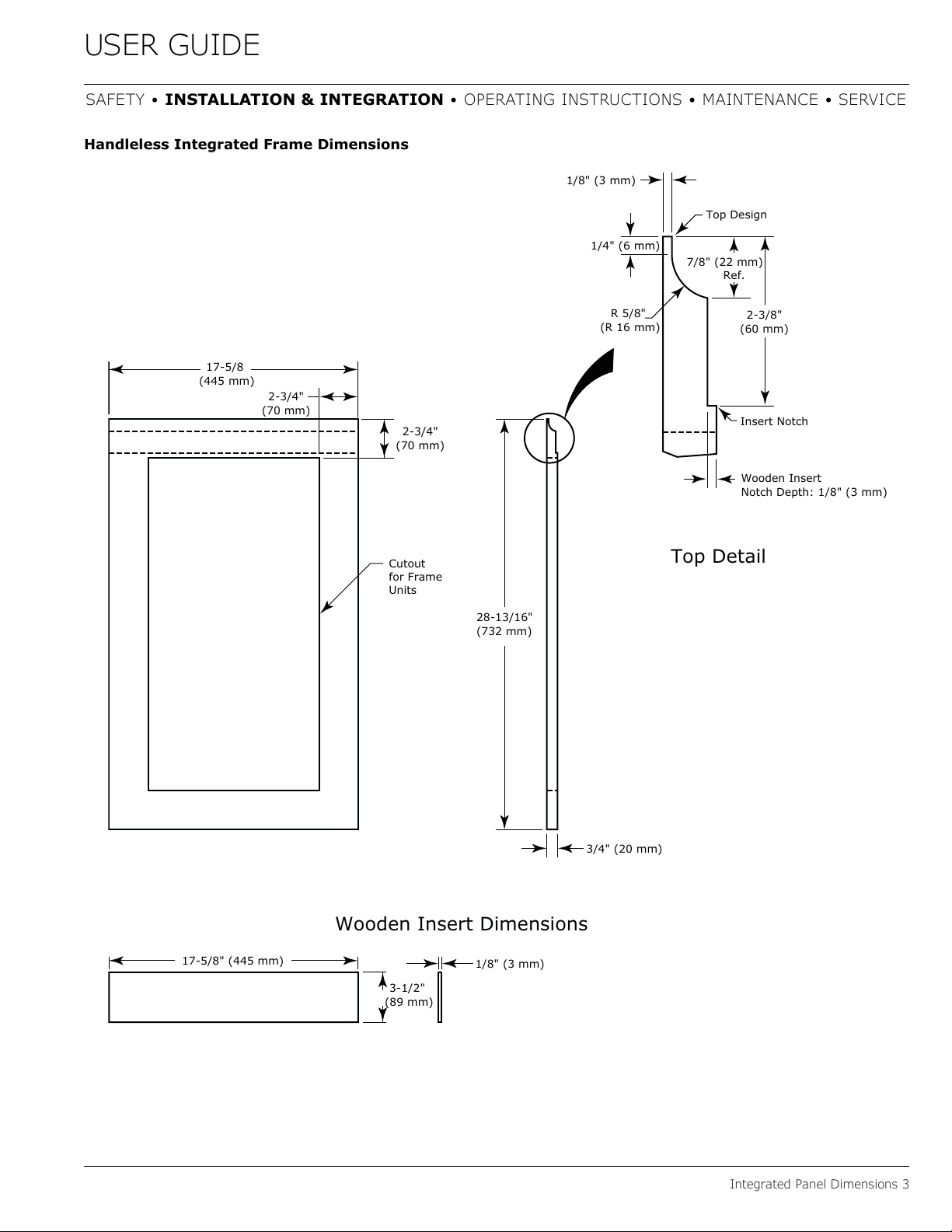
1. Cut the main panel to the dimensions below. For
details, see the drawings on the next page.
2. Create the top design for the handleless feature and
the 1/8" (3 mm) notch for the insert(s) indicated on
the appropriate Top Detail drawing, on the next page.
3. Prepare the insert(s) that will back up the handleless
design. Wooden Insert – Cut 1/8" (3 mm) thick
wooden insert(s) to the appropriate dimensions below.
4. Optional: Stain or finish frame and wooden insert to
desired stain or color. Be sure to closely follow the
instructions provided by the manufacturer.
NOTICE
If finishing panel or wooden insert, all sides
must be finished to prevent warping.
5. Attach the insert to the frame. Wood glue or equivalent
adhesive should be used to attach insert to frame.
Main panel width Main panel height
17-5/8" (445 mm) 28-13/16" (732 mm)
Wooden insert width Wooden insert height
17-5/8" (445 mm) 3-1/2" (89 mm)
Cutout
Integrated Frame
Main Panel
Wooden Insert
Top Design
and Insert Notch
Attach Wooden Insert
5
USER GUIDE
Integrated Panel Dimensions 3
SAFETY • INSTALLATION & INTEGRATION • OPERATING INSTRUCTIONS • MAINTENANCE • SERVICE
Handleless Integrated Frame Dimensions
3/4" (20 mm)
28-13/16"
(732 mm)
2-3/4"
(70 mm)
2-3/4"
(70 mm)
R 5/8"
(R 16 mm)
1/8" (3 mm)
1/4" (6 mm)
Wooden Insert
Notch Depth: 1/8" (3 mm)
2-3/8"
(60 mm)
7/8" (22 mm)
Ref.
Top Detail
Insert Notch
Top Design
1/8" (3 mm)
3-1/2"
(89 mm)
17-5/8" (445 mm)
Wooden Insert Dimensions
17-5/8
(445 mm)
Cutout
for Frame
Units
6
USER GUIDE
Integrated Panel Dimensions 4
SAFETY • INSTALLATION & INTEGRATION • OPERATING INSTRUCTIONS • MAINTENANCE • SERVICE
EXTENDED INTEGRATED FRAME
NOTICE
Due to differences in surrounding cabinetry the
panel may not perfectly align with door. The
procedure below is designed to provide a
finished panel that seamlessly integrates with
surrounding cabinetry.
Panel Preparation
An extended integrated panel can be used to maintain
alignment with an adjacent extended cabinet height or a
reduced toe-kick/grille application.
1. Cut the panels to the dimensions listed in the
appropriate diagram on the next page.
2. Optional: Stain or finish panel to desired stain or color.
Be sure to closely follow the instructions provided by
the manufacturer.
3. Optional: Install handles and hardware.
NOTICE
The door panel must not weigh more than 20 lbs
(10 kg).
It is important to ensure that all drilled holes are
drilled to the correct depth in order to avoid
splits in the wood when hardware is installed.
Appliance will need up to 34-1/2" (876 mm) to
the underside of the counter to leave room for
leveling adjustments.
When applying an integrated frame to a unit,
ensure that both sides are finished in order to
prevent warping. In some installations, the
panel may be visible through the glass while the
door is open.
7
USER GUIDE
Integrated Panel Dimensions 5
SAFETY • INSTALLATION & INTEGRATION • OPERATING INSTRUCTIONS • MAINTENANCE • SERVICE
3-5/16" (89 mm)
to
4-5/16" (114 mm)
U-Line
Unit
U-Line
Unit
Integrated Panel
Integrated Panel/Integrated Frame
Front Side
Front Side
3-5/16" (89 mm)
to
4-5/16" (114 mm)
Floor
Cabinet
> 3-5/16"
(> 89 mm)
3-5/16" (89 mm)
to
1" (25 mm)**
U-Line
Unit
Extended Integrated Panel/Extended Integrated Frame
Floor
Cabinet
3-5/16" (89 mm)
to
1" (25 mm)**
*
U-Line
Unit
Integrated Panel
* Panel can extend beyond the door
frame.
** A minimum of 1" (25 mm) from
the floor is required for proper
ventilation.
8
USER GUIDE
Integrated Panel Dimensions 6
SAFETY • INSTALLATION & INTEGRATION • OPERATING INSTRUCTIONS • MAINTENANCE • SERVICE
Extended Integrated Frame Dimensions
NOTICE
The minimum border thickness for a 30"
(762 mm) tall integrated frame is 2-3/4"
(70 mm). The top/bottom border of the frame
must account for any additional length.
BACK SURFACE MUST HAVE AMPLE FLAT SURFACE
TO MOUNT INTEGRATED FRAME FLAT AND
WITHOUT INTERFERENCE
17-5/8"
(445 mm)
3/4"
(20 mm)
2-3/4" MIN
(70 mm MIN)
Integrated Frame
30.0" -
33-7/8"
(762 mm -
860 mm)*
* A minimum of 1" (25 mm) is required from the
floor to the bottom of the extended integrated
panel/frame for proper ventilation.
9
USER GUIDE
Integrated Grille - Plinth Dimensions 1
SAFETY • INSTALLATION & INTEGRATION • OPERATING INSTRUCTIONS • MAINTENANCE • SERVICE
Integrated Grille - Plinth
Dimensions
PREPARE AND INSTALL INTEGRATED GRILLE
(PLINTH STRIP/BASE FASCIA)
1. Use the dimensions provided in the diagram to cut and
shape your integrated grille (plinth strip/base fascia)
panel. Recommended panel thickness is between 1/4"
(6 mm) and 3/8" (9 mm).
2. Finish or stain your grille (plinth strip/base fascia)
panel to match your surrounding furniture. Finish
front, back and edges to prevent warping. Carefully
follow the manufacturer’s recommendations for finish
application and cure times.
3. Apply double sided tape to the backside of the
integrated grill (plinth strip/base fascia). Use the
diagram below for reference. U-Line recommends
3M™VHB™tape, a high strength bonding tape.
4. Remove backing paper from double sided tape.
5. Carefully align grille (plinth strip/base fascia) over
integrated panel and press into position.
INTEGRATED GRILLE (PLINTH STRIP/BASE
FASCIA) DIMENSIONS
Apply Tape To Shaded Area
1" (25 mm)
1-9/16"
(40 mm)
17-7/8"
(455 mm)
14-3/4"
(375 mm)
3-5/16"
(84 mm)
1-9/16"
(40 mm)
10
USER GUIDE
Integrated Panel Installation 1
SAFETY • INSTALLATION & INTEGRATION • OPERATING INSTRUCTIONS • MAINTENANCE • SERVICE
Integrated Panel Installation
1. Fully open door.
2. Starting at corner, pull
gasket away from door.
3. Continue to pull gasket
free from gasket channel.
4. Upon removal, lay gasket down on a flat surface.
5. The panel should be aligned with the outside edge
(opposite the hinge) and high enough to align with the
highest point in the door.
NOTICE
Due to differences in floor construction or
surrounding cabinetry, the panel may not sit
flush with the top of the door.
6. Secure integrated
panel to door using
clamps. A robust
tape may also be
used. U-Line
recommends the
use of bar clamps
to secure the panel
to the door. If using
tape, be certain the
tape will not
damage panel finish
upon removal.
7. Using a 7/64"
(3 mm) drill bit, drill
6 pilot holes into
the wood panel 1/2"
(12 mm) deep using
the holes in the
door frame as a
guide.
NOTICE
It is important to ensure that all drilled holes are
drilled to the correct depth in order to avoid
splits in the wood when hardwood is installed.
8. Locate 6 of the #6x 1-1/2" (38 mm) screws provided
with your unit.
9. Using a Phillips screwdriver, place one screw into each
of the 6 pilot holes and screw down. Do not overtighten
screws.
Align Panel
Against
Door Edge
First
Align Top Of Panel With Highest Point Of Door
Door
Panel
Wood
Panel
Door/Drawer
Bar
Clamp
Bar
Clamp
11
USER GUIDE
Integrated Panel Installation 2
SAFETY • INSTALLATION & INTEGRATION • OPERATING INSTRUCTIONS • MAINTENANCE • SERVICE
10.Be sure the screws force their way past the opening on
the gasket channel and sit flush against the bottom of
the channel.
11.Remove clamps from door.
NOTICE
If panel requires additional adjustment after
removing clamps, slightly loosen each screw and
adjust panel as necessary. Tighten screws upon
completion.
12.Starting at the corners, re-install the gasket into the
gasket channel in the frame. Make sure the gasket is
fully seated. This may take some force.
Integrated Panel
Integrated Panel
12
USER GUIDE
Grille - Plinth Installation 1
SAFETY • INSTALLATION & INTEGRATION • OPERATING INSTRUCTIONS • MAINTENANCE • SERVICE
Grille - Plinth Installation
REMOVING AND INSTALLING GRILLE
(PLINTH STRIP/BASE FASCIA)
WARNING
!
Disconnect electric power to the unit before
removing the grille (plinth strip/base fascia).
When using the unit, the grille (plinth strip/base
fascia) must be installed.
WARNING
!
DO NOT touch the condenser fins. The condenser
fins are SHARP and can be easily damaged.
Removing the grille
(plinth strip/base fascia)
1. Disconnect power to the unit.
2. Loosen the two screws (1).
3. Remove grille (plinth strip/base fascia) (2) from unit.
Installing the grille
1. Align cabinet and grille holes and secure, but do not
over tighten grille (plinth strip/base fascia) screws (1).
2. Reconnect power to the unit.
1
2
13

Other U-Line Refrigerator manuals

U-Line U-LINE 29WHTP User manual

U-Line

U-Line U-LINE 29WHTP User manual

U-Line WINE CAPTAIN 2115R User manual

U-Line

U-Line WINE CAPTAIN 2115R User manual

U-Line 3024DWR Installation manual

U-Line

U-Line 3024DWR Installation manual

U-Line Combo U-CO1224FINT-00A Installation manual

U-Line

U-Line Combo U-CO1224FINT-00A Installation manual

U-Line ADA Combo User manual

U-Line

U-Line ADA Combo User manual

U-Line UCBR592-SS01A Installation manual

U-Line

U-Line UCBR592-SS01A Installation manual

U-Line WINE CAPTAIN 2115RS User manual

U-Line

U-Line WINE CAPTAIN 2115RS User manual

U-Line 2000 SERIES User manual

U-Line

U-Line 2000 SERIES User manual

U-Line Echelon 2015R User manual

U-Line

U-Line Echelon 2015R User manual

U-Line 2175DWRR User manual

U-Line

U-Line 2175DWRR User manual

U-Line U1224RS00B Installation manual

U-Line

U-Line U1224RS00B Installation manual

U-Line UHRE124BS01A Installation manual

U-Line

U-Line UHRE124BS01A Installation manual

U-Line U-1224KEGRSOD-00A Installation manual

U-Line

U-Line U-1224KEGRSOD-00A Installation manual

U-Line Commercial UCRE515-SG33A Installation manual

U-Line

U-Line Commercial UCRE515-SG33A Installation manual

U-Line 3036RRGLS-00B User manual

U-Line

U-Line 3036RRGLS-00B User manual

U-Line UACP115-IS01A Installation manual

U-Line

U-Line UACP115-IS01A Installation manual

U-Line 2175R Owner's manual

U-Line

U-Line 2175R Owner's manual

U-Line UORE124-SS31A Installation manual

U-Line

U-Line UORE124-SS31A Installation manual

U-Line U-2218RGLS-00B Installation manual

U-Line

U-Line U-2218RGLS-00B Installation manual

U-Line UOKR124 Installation manual

U-Line

U-Line UOKR124 Installation manual

U-Line 2115RSOD User manual

U-Line

U-Line 2115RSOD User manual

U-Line Echelon Combo C2275DWR User manual

U-Line

U-Line Echelon Combo C2275DWR User manual

U-Line UHRE518 Installation manual

U-Line

U-Line UHRE518 Installation manual

U-Line U-2245RINT-00B Installation manual

U-Line

U-Line U-2245RINT-00B Installation manual

Popular Refrigerator manuals by other brands

inventum KV1500W user manual

inventum

inventum KV1500W user manual

Whirlpool ED25DQXDB00 Use and care guide

Whirlpool

Whirlpool ED25DQXDB00 Use and care guide

Viking VCSB5483 Use & care manual

Viking

Viking VCSB5483 Use & care manual

Samsung RL55VQBRS Premium 2m Fridge Freezer user manual

Samsung

Samsung RL55VQBRS Premium 2m Fridge Freezer user manual

LG LSC 26905TT user guide

LG

LG LSC 26905TT user guide

Panasonic NR-B53V2 Service manual

Panasonic

Panasonic NR-B53V2 Service manual

UNITED UCS-3164M instruction manual

UNITED

UNITED UCS-3164M instruction manual

Norcold 1210 - parts list

Norcold

Norcold 1210 - parts list

VWR International 47747-222 Installation and operation manual

VWR International

VWR International 47747-222 Installation and operation manual

Eurotech Design ED-RF132SS instruction manual

Eurotech Design

Eurotech Design ED-RF132SS instruction manual

Frigidaire FPE-26VWM Use and care guide

Frigidaire

Frigidaire FPE-26VWM Use and care guide

Hokkaido HKEN-HCNN 642XR Service manual

Hokkaido

Hokkaido HKEN-HCNN 642XR Service manual

Carrier TRANSICOLD Integra 35X Operation and service manual

Carrier TRANSICOLD

Carrier TRANSICOLD Integra 35X Operation and service manual

Haier A2FE735CXJ user manual

Haier

Haier A2FE735CXJ user manual

Summit FF6BI series Specifications

Summit

Summit FF6BI series Specifications

Dometic RM211 Operating and installation instructions

Dometic

Dometic RM211 Operating and installation instructions

KitchenAid KBRO36FMX01 parts list

KitchenAid

KitchenAid KBRO36FMX01 parts list

Electrolux ER2650B instructions

Electrolux

Electrolux ER2650B instructions

manuals.online logo
manuals.online logoBrands
  • About & Mission
  • Contact us
  • Privacy Policy
  • Terms and Conditions

Copyright 2025 Manuals.Online. All Rights Reserved.