8
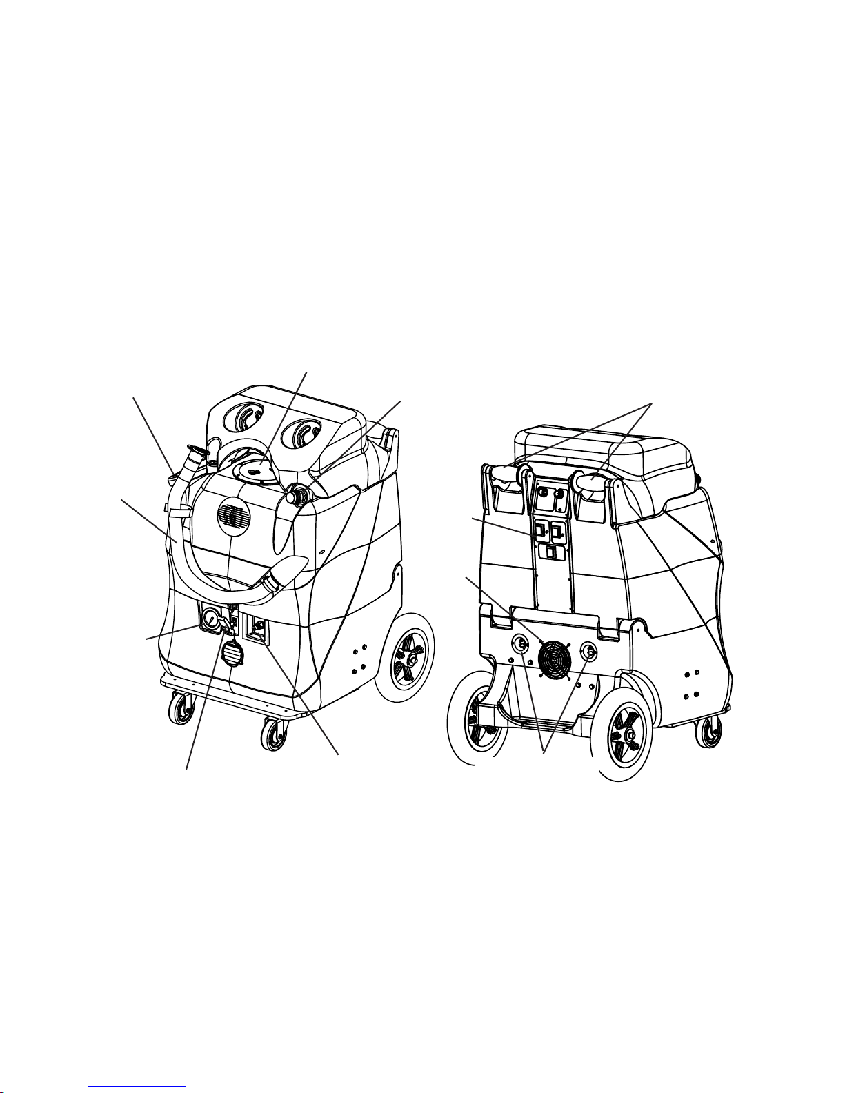
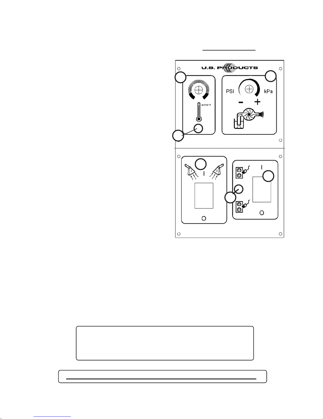
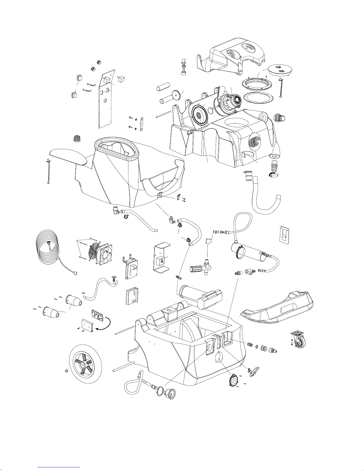
SOLUS-500 EXTRACTOR
PART LIST
1 FP578 Switch, DPDT,with cover
3 78B Light, red
3A 78 Light, green
5 248 Knob, red
5A FP544 Potentiometer, heat, w/wires & knob
6 249 Knob, blue
6A FP543 Potentiometer, pump, w/wires & knob
7 2093A Switch plate
8 4404C Mating bar
9 2106 Handle
9A 1590 Grip, handle
10 2105 Wheel, handle
11 FP478 Float assembly, electric
12 801E Hinge pin, 7”
13 FP594 Tank, Vacuum
13A VC-BLK1 Cover, for vacuum motors
14 2013A Gasket, vacuum
15 408E Vacuum motor, 120V
15A 1589 Screen, 1/8 S/S mesh
16 2086A Lid & ring, vacuum
17 1074 Gasket, vacuum lid
18 FP436 Chain, 8”
19 907 Hose barb, 1-1/2”
20 1130 Strap, Velcro, 9”
21 1060C Cap, drain hose
22 1518 Hose Clamp
23 1060B Hose, drain
24 FP582 Tank, Holding
25 FP545 Lid & chain, Holding Tank
26 909A Latch strike
28 1113 Hose barb, 90°, 1/2” hose
28A 1115 Hose barb, 90°, 3/8” hose
29 925 Hose, 3/8” ID X 20”
31 166 Hose clamp
33 946 Hose, 1/2” ID X 17”
34 207A Filter, pump inlet
36 See Miscellaneous *
37 918 Heat Sink plate
38 FP361 Motor Speed Control PCB, pump
40 FP225 Vacuum Motor Control PCB
41 2014 Fan, 120V
42 2015 Guard, fan
43 2B1 Screw, 6-32 X 2-1/4”
44 1057B Power Cord, 12/3, 25 ft
45 1062 Receptacle, AC power in
46 1476 Strap, 17”
49 FP336 PCB mounting track, 4”
50 923B Dual Cord Sensor PCB
51 198 Hose clamp
52 948B Motor, DC, for pump
53 FP592 Pump complete, no mtr
54 FP542 Hose assembly, pump to gauge
55 801D Hinge pin, 4.75”
56 27A Axle Cap
57 2092 Wheel, 12”
58 910-23.75 Axle rod
60 BUPE-BLK Base compartment
62 905 Castor, 4”
63 2165 Gauge, Pump pressure
64 928 Louver, 3”, gray
65 FP585 Castor Plate
66 908 Latch
67 45 Quick Disconnect, male. 1/4 p.t.
68 115 Washer, fiber
69 116A Bushing, Teflon
70 92A Nipple, 1/4 p.t. S/S
71 216 Elbow, brass
72 FP540 Heat Exchanger, complete
73 455 Mount bracket, heater
74 223 Quick Disconnect, male
75 945D Unloader valve
77 1373A Hose assembly, heater inlet
78 2183 Hose, S/S, braided, heater outlet
ITEM PART No DESCRIPTION
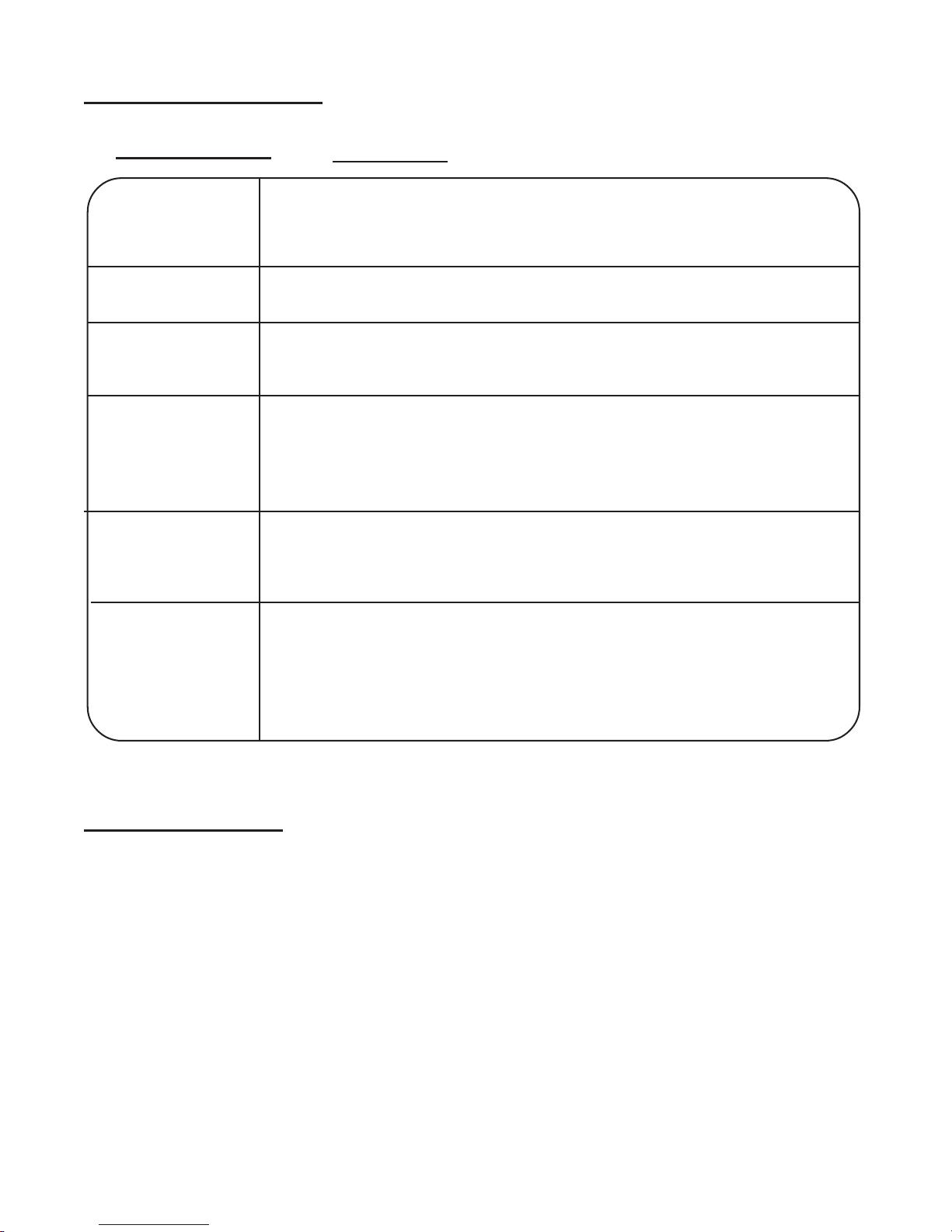
MISCELLANEOUS PARTS
*FP194E Heat repair kit includes thermistor
control, thermistor probe & cutout
950CP Pump rebuild kit, valves and o-rings
250 Pump rebuild kit, piston and seals
950D Cam/bearing, pump drive
FP619 Bag, pre-filter for recovery inlet
120V
ITEM PART No DESCRIPTION
partsin kits arenot sold separately