uAvionix AV-30-E User manual

UAV-1004234-001, AV-30-E, Installation Manual 1 Revision A
AV-30-E
Installation Manual

UAV-1004234-001, AV-30-E, Installation Manual 2 Revision A
© 2020 uAvionix Corporation. All rights reserved.
Except as expressly provided herein, no part of this guide may be
reproduced, transmitted, disseminated, downloaded or stored in any
storage medium, for any purpose without the express written permission
of uAvionix. uAvionix grants permissions to download a single copy of
this guide onto an electronic storage medium to be viewed for personal
use, provided that the complete text of this copyright notice is retained.
Unauthorized commercial distribution of this manual or any revision
hereto is strictly prohibited.
uAvionix® and Ping® are registered trademarks of uAvionix Corporation
and may not be used without express permission of uAvionix.
AV-30, AV-30-E, and AV-30-C are trademarks of uAvionix Corporation
and may not be used without express permission of uAvionix.
Patent uavionix.com/patents

UAV-1004234-001, AV-30-E, Installation Manual 3 Revision A
1 Revision History
Revision
Date
Comments
A
6/2/2020
Initial release

UAV-1004234-001, AV-30-E, Installation Manual 4 Revision A
2 Warnings / Disclaimers
All device operational procedures must be learned on the ground.
uAvionix is not liable for damages arising from the use or misuse of this
product.
This equipment is classified by the United States Department of
Commerce's Bureau of Industry and Security (BIS) as Export Control
Classification Number (ECCN) 7A994.
These items are controlled by the U.S. Government and authorized for
export only to the country of ultimate destination for use by the ultimate
consignee or end-user(s) herein identified. They may not be resold,
transferred, or otherwise disposed of, to any other country or to any
person other than the authorized ultimate consignee or end-user(s),
either in their original form or after being incorporated into other items,
without first obtaining approval from the U.S. government or as otherwise
authorized by U.S. law and regulations.

UAV-1004234-001, AV-30-E, Installation Manual 5 Revision A
3 Table of Contents
1Revision History................................................................................. 3
2Warnings / Disclaimers...................................................................... 4
3Table of Contents .............................................................................. 5
4AV-30-E System Information ............................................................. 7
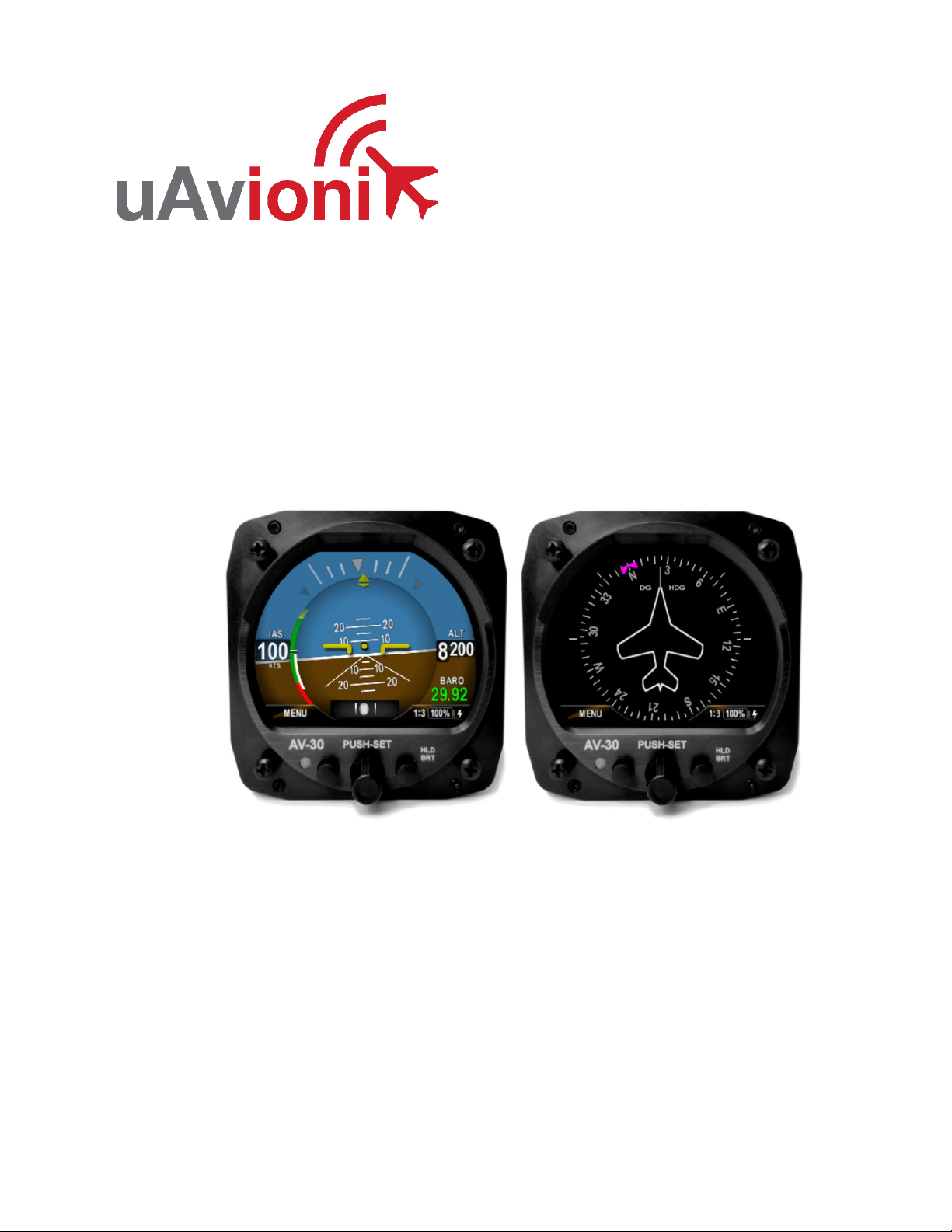
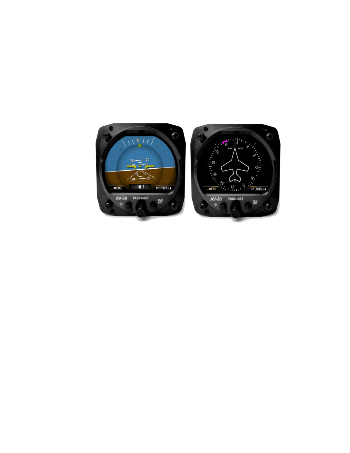
4.1 System Description...................................................................... 7
4.2 System Functions ........................................................................ 9
4.3 System Specifications................................................................10
5Design Standards ............................................................................11
5.1 Applicable Performance Standards ...........................................12
6Installation Locations & Operating Modes.......................................13
6.1 Installation Locations ................................................................. 13
6.2 Operating Mode Configuration ..................................................13
7Functionality and Required Interfaces.............................................14
7.1 Aircraft Systems Connections ...................................................14
7.2 Feature Matrix............................................................................15
7.2.1Power Input (Required)........................................................16
7.2.2Pitot and Static Interfaces (Required/Optional) ...................16
7.2.3Outside Air Temp Input (Optional)....................................... 16
7.2.4Audio Output (Optional) ....................................................... 17
7.2.5GPS Interface (Optional) .....................................................17
7.2.6tailBeaconX Control (optional).............................................18
7.3 Internal Battery Operation .........................................................18
7.3.1General ................................................................................18
8Equipment Installation .....................................................................19
8.1 Overview ....................................................................................19
8.2 Supplied Components ............................................................... 19
8.3 Non-Supplied Components ....................................................... 19
8.4 Mechanical Drawing .................................................................. 20
8.5 Mounting Screw Length Restriction........................................... 21
8.6 Wiring Diagrams ........................................................................22
8.7 Bonding Requirements ..............................................................24
8.8 Unit Pinout ................................................................................. 25
9Setup & Configuration .....................................................................26
9.1 Startup and Common Controls .................................................. 26
9.2 Available Menus ........................................................................27
9.3 Install Menu Activation...............................................................28

UAV-1004234-001, AV-30-E, Installation Manual 6 Revision A
9.4 Install Menu Settings .................................................................29
9.5 Mandatory Settings....................................................................30
9.5.1Unit Function........................................................................30
9.5.2Function Lock....................................................................... 30
9.5.3Trims ....................................................................................30
9.5.4V-Speeds .............................................................................30
9.5.5Display Units ........................................................................30
9.5.6Serial Inputs .........................................................................31
9.5.7Demo Mode .........................................................................31
9.6 System Checkout.......................................................................31
9.6.1Alignment .............................................................................31
9.6.2OAT Interface.......................................................................32
9.6.3GPS Navigator Interface......................................................32
9.6.4tailBeaconX control Interface...............................................33
10 Troubleshooting ...........................................................................34
11 Serial Interface Specification ....................................................... 35
12 Field Update Capability................................................................ 36

UAV-1004234-001, AV-30-E, Installation Manual 7 Revision A
4 AV-30-E System Information
4.1 System Description
The uAvionix AV-30-E is a fully digital multi-mode instrument that
mounts in the legacy 3 1/8” round instrument panel.It can be field
configured as either an Attitude Indicator (AI) or a Directional Gyro
(DG) indicator. It is fully self-contained with dual-precision inertial and
pressure sensors and allows for a wide variety of pilot customization.
Figure 1 - AV-30-E Multi Mode AI/DG – Basic Display
When configured as an AI, primary attitude and slip are always
displayed. The un-used portions of the display area can be customized
by the pilot to show a variety of textual and graphical data-overlay
fields. Three pages may be customized by the pilot while a fourth page
presents a fully decluttered view of only attitude and slip.
When configured as a Directional Gyro (DG), direction of flight
information is presented. The flight direction can be configured to be
presented as non-slaved heading or inertially stabilized GPS track
when connected to an external GPS navigator. Multiple display
presentations, including compass rose, GPS HSI, and GPS Arc views
can be selected by the pilot. The un-used portions of the display area
can similarly be configured for a variety of textual data-overlays.
In both operating modes, the pilot may select from multiple visual styles
which are intended to improve visual compatibility with legacy aircraft
instrumentation and preserve the look-and-feel of older aircraft
applications.

UAV-1004234-001, AV-30-E, Installation Manual 8 Revision A
A wide variety of supplemental functions, including audio alerting,
derived angle of attack presentation, g-load display, and more are
provided. An internal, rechargeable LiPo battery allows for operation
for a nominal 2 hours in the event of aircraft power loss and 30 minutes
minimum under all temperature conditions.

UAV-1004234-001, AV-30-E, Installation Manual 9 Revision A
4.2 System Functions
Primary Functions:
- Primary Attitude (AI Mode)
- Primary Slip (AI Mode)
- Primary Direction of Flight Indication (DG Mode)
Supplemental Functions:
- Indicated Airspeed
- Altitude
- V-Speeds
- Angle of Attack
- Vertical Trend
- Vertical Speed
- Set Altitude
- Heading
- Bus Voltage
- G Load
- Outside Air Temp
- True Airspeed
- Density Altitude
- GPS Navigator / Waypoint Data
- GPS Navigator Nav Data
- GPS Navigator Route Line
- Heading Bug
Audio and Visual Alerting Functions:
- AoA Alerting
- G Limit Alerting
- Excessive Roll Alerting
Misc. Functions:
- Internal Battery Operation
- Auto / Manual Brightness

UAV-1004234-001, AV-30-E, Installation Manual 10 Revision A
4.3 System Specifications
Electrical Attributes
Input Voltage Nominal +10 to +32 VDC
Input Voltage Max +60 VDC
Input Power Nominal 6 Watts (0.5 Amps @ 12VDC)
Input Power Max 12 Watts (1.0 Amps @ 12VDC)
Required Circuit Breaker
2 Amp
Operation on Battery 2 Hrs Typ @ 20°C / 30 Min Minimum @ -20C
Physical Attributes
Mounting Configuration 3 1/8” Round Instrument Hole
Dimensions wo/Connector
3.38 x 3.38 x 1.6 Inches
Weight 0.56 Lbs.
Electrical Connector 15 Pin Male D-Sub
Pneumatic Connectors ¼” OD Quick Connect
Mounting (4X) #6-32 Machine Screws
Case Material Billet Aluminum
Environmental
Ground Survival Low -55°C
Operating Low
-20°C
Ground Survival High +85°C
Operating High
+55°C
Altitude 25,000 Feet Max
Optical Characteristics
Diagonal Size 3” Circular
Contrast Ratio (Typical) 500
Brightness (Typical) 1000 cd/m2
Viewing Angle Left/Right 60°
Viewing Angle Up 45°
Viewing Angle Down 10°
Backlight Lifetime (Typical)
50,000 Hrs
Table 1 - System Specifications

UAV-1004234-001, AV-30-E, Installation Manual 11 Revision A
5 Design Standards
This installation manual provides mechanical and electrical information
necessary to install the AV-30-E. The content of this manual assumes
use by competent and qualified personnel using standard maintenance
procedures in accordance with Title 14 of the Code of Federal
Regulation (CFR) and other related accepted procedures.
The design basis for the AV-30-E is 14 CFR Part 23, Amendment 23-61.
Installation is approved as a Level A system and is robust to High
Intensity Radiated Field (HIRF) and lightning levels applicable for both
metallic and non-metallic aircraft.
The installer must ensure that all installation limitations as
defined in this document are observed.
The internal battery capacity has been tested and verified to provide 30
minutes of operational capacity (with reserve), and meets the
requirements defined in CFR 23.1311(a)(5) and 23.1353(h), allowing
independent operation from the primary electrical power system.
See Section 7.3 Internal Battery Operation for additional battery
operational characteristics.

UAV-1004234-001, AV-30-E, Installation Manual 12 Revision A
5.1 Applicable Performance Standards
The AV-30-E was designed to, and satisfied the applicable
performance requirements defined in the following design standards:
MOPS
Title
Category
SAE AS8019
Airspeed Instruments
Type B
SAE AS392C
Altimeter, Pressure Actuated, Sensitive
Type
Type I
SAE AS8005A
Standard Temperature Instruments
Class IIIc
SAE AS8034
Airborne Multipurpose Electronic Displays
N/A
RTCA DO-334
Attitude and Heading Reference Systems
(AHRS)
A5 H9 T7
ASTM F3011-13
Angle Of Attack System
N/A
RTCA DO-347
Cert and Test for Small and Med Lipo
Batteries
Medium Size
Table 2 - Applicable Performance Standards

UAV-1004234-001, AV-30-E, Installation Manual 13 Revision A
6 Installation Locations & Operating Modes
6.1 Installation Locations
The following figure shows a typical “six-pack” and one possible
arrangement of instrument locations:
AI
DG
AI/DG
Figure 2 – Mechanical Gauge Replacement
Note that the physical arrangement in many aircraft varies from the
traditional “T” configuration shown above.The AI/DG locations are
examples of installation locations as a non-required instrument.
The existing mechanically based altimeter and airspeed
indicator must remain in their factory locations for this
installation configuration.
6.2 Operating Mode Configuration
The AV-30-E operating mode is configured during installation and can
be set as follows:
•Unit locked as a dedicated Attitude Indicator (AI Mode)
•Unit locked as a dedicated Direction Indicator (DG Mode)
•Unit can be toggled between AI and DG mode by the pilot
If the functionality is not locked, pressing and holding the rotary knob
will toggle between AI and DG mode.

UAV-1004234-001, AV-30-E, Installation Manual 14 Revision A
7 Functionality and Required Interfaces
7.1 Aircraft Systems Connections
All aircraft systems connections are provided on the single 15-Pin D-
sub connector and two quick-connect pneumatic fittings. Various
interfaces are optional as indicated in the following diagrams.
Aircraft Power
Pitot System
Static System
ELECTRICAL INTERFACES
Digital
Optional OAT Probe
Analog
Optional Audio Out
Analog
AIRCRAFT SYSTEMS
Optional GPS Navigator
AV-30-C
PNEUMATIC
CONNECTORS
Figure 3 – AV-30-E Aircraft Systems Interfaces – AI Mode
Figure 4 – AV-30-E Aircraft Systems Interfaces – DG Mode
Aircraft Power
Optional Pitot System
Optional Static System
ELECTRICAL INTERFACES
Digital
Optional OAT Probe
Analog
AIRCRAFT SYSTEMS
Optional GPS Navigator
AV-30-C
PNEUMATIC
CONNECTORS
Optional Audio Out
Analog
Audio Output Not Supported In DG Mode

UAV-1004234-001, AV-30-E, Installation Manual 15 Revision A
7.2 Feature Matrix
The following matrix shows primary and supplemental data and any
required external interface.
Feature
AI Mode
DG Mode
Required Interface
Primary Attitude and Slip
Primary Attitude
None
Primary Slip
None
Reversionary Attitude / Slip
None
Primary Direction of Flight Indication
Direction Tape (DG / GPS)
None / GPS Navigator
Direction Rose (DG)
None
Direction Arc (GPS)
GPS Navigator
Direction HSI (GPS)
GPS Navigator
Supplemental Data Overlays – Pilot Configurable (Textual or Graphical)
Indicated Airspeed (Textual)
Pitot / Static
V-Speeds (Graphical)
Pitot / Static
Baro Altitude (Textual)
Pitot / Static
Angle Of Attack (Graphical)
Pitot / Static
Vertical Trend (Graphical)
Pitot / Static
Vertical Speed (Textual)
Pitot / Static
Set Altitude (Textual)
None
Heading (Textual)
None
Bus Voltage (Textual)
None
G Load (Textual)
None
Outside Air Temp (Textual)
OAT Probe
True Airspeed (Textual)
Pitot / Static / OAT Probe
Density Altitude (Textual)
Pitot / Static / OAT Probe
GPS Navigation / Waypoint Data
Textual Nav Data
GPS Navigator
Graphical Nav Data
GPS Navigator
Heading Bug
Hdg Bug – Ref Only, no AP
None
Audio and Visual Alerting
AoA Alerting
Pitot / Static
G Limit Alerting
None
Excessive Roll Alerting
None
Misc.
Internal Battery Operation
Pitot / Static
Auto / Manual Brightness
None
tailBeaconX Control
tailBeaconX serial
Table 3 – Feature Matrix

UAV-1004234-001, AV-30-E, Installation Manual 16 Revision A
7.2.1 Power Input (Required)
Power input is required and connects to the aircraft’s power bus.
Input range is compatible with both 12V and 24V aircraft. Internally,
this power is diode OR’ed with the internal battery via a processor-
controlled switch. This architecture allows the unit to continue
operation if external power fluctuates or is completely lost.
Each AV-30-E must have a dedicated, properly labeled, pilot
resettable circuit breaker as part of the installation. Power for the
unit may be supplied from either the avionics bus or the main battery
master relay.
7.2.2 Pitot and Static Interfaces (Required/Optional)
In addition to directly displayable data such as airspeed and altitude,
pitot and static inputs are utilized within the probeless Angle of
Attack algorithm and provide the underlying source for various air-
data type data overlays (TAS & DALT).
When installed as a DG, pitot and static connections are not required
unless TAS and DALT are desirable (also requires a dedicated OAT
probe). See the detailed wiring diagram for more information.
7.2.3 Outside Air Temp Input (Optional)
The optional outside air temperature interface requires a dedicated
external analog probe. This port connection is compatible with the
Davtron P/N C307PS (not supplied).
This is a differential two-wire current source based on the Analog
Devices AD590KH component and supplies a current that
corresponds to the ambient temperature.
If two displays are connected to the same probe, the current
will be split between the two and incorrect readings will be
shown by both.
The sensor reading must be trimmed during the installation process
to compensate for probe-to-probe variations.

UAV-1004234-001, AV-30-E, Installation Manual 17 Revision A
The OAT probe is automatically detected by the system, and when
detected, allows temperature related parameters to be selected for
display by the pilot.
If the OAT probe is not detected, display of these parameters will
automatically be inhibited.
7.2.4 Audio Output (Optional)
The optional audio panel connection is a low-voltage analog output
that is designed to connect directly to an audio panel (typically a
non-switched input). High power outputs capable of directly driving a
cockpit speaker are not provided.
When installed as a DG, no audio alerting is supported, and this
output should remain disconnected.
In non-metallic, IFR capable aircraft, this connection MUST
remain disconnected due to lightning strike limitations.
7.2.5 GPS Interface (Optional)
The GPS interface is an optional RS-232 serial input that is
compatible with the industry standard “Moving Map” output provided
by most panel mounted GPS units, and NMEA serial interfaces
provided by most hand-held GPS units.
This is a text/binary protocol output by the GPS navigator that
contains situational awareness information such as ground speed,
track, distance to destination, cross track, etc, and is typically utilized
by remote mapping/display products to provide additional pilot
awareness.
This output does not provide IFR compliant lateral or vertical
guidance, therefore all deviation related data presented is for VFR
operations only.
The AV-30-E does no computations or operations on the data
obtained from the GPS navigator, and simply displays the received
data in a textual or graphical format as configured by the pilot.

UAV-1004234-001, AV-30-E, Installation Manual 18 Revision A
This serial interface may be connected in parallel between
multiple AV-30 units and is supported in both the AI and DG
modes.
The supported protocols are contained in Section 14- Serial Interface
Specification.
7.2.6 tailBeaconX Control (optional)
The AV-30-E has the option of being the transponder control
interface for an installed tailBeaconX. This requires an RS-232 serial
connection from the tailBeaconX to the AV-30-E. tailBeaconX can
also act as your GPS source using the existing serial connection.
7.3 Internal Battery Operation
7.3.1 General
The internal battery consists of a rechargeable LiPo battery system
with automatic recharge, self-test and power switching capability.
The internal battery capacity will provide approximately 2 hours of
operation at standard temperatures and 30 minutes (minimum) of
operational capacity over the operational temperature range.
See the Internal Battery Operation section within the Pilots Guide for
additional operational information.

UAV-1004234-001, AV-30-E, Installation Manual 19 Revision A
8 Equipment Installation
8.1 Overview
Installation consists of the following steps:
•Remove / relocate any legacy instrumentation
•Add or locate an appropriate power source / breaker
•Wire power and systems interfaces as needed
•Mount the unit to the instrument panel with supplied screws
•Apply power and perform setup
8.2 Supplied Components
Component
Part Number
Description
AV-30-E Unit
UAV-1003429-001
AV-30-E Unit
AV-30-E Installation
Kit
UAV-1004091-001 Installation Kit
Table 4 – Supplied Components
8.3 Non-Supplied Components
Component
Description
Pitot / Static Tubing
Length as required
Pitot Static T’s
Quantity as required
Circuit Breakers (2A)
One required for each instrument
OAT Probe
Davtron P/N C307PS
Table 5 – Non-Supplied Components

UAV-1004234-001, AV-30-E, Installation Manual 20 Revision A
8.4 Mechanical Drawing
Figure 5 – Mechanical Drawing
Other manuals for AV-30-E
5
Table of contents
Other uAvionix Monitor manuals