Ublox ZED-F9R User manual

UBX-22035176 - R01
C1-Public www.u-blox.com
ZED-F9R
Getting started with high-precision sensor fusion
Application note
Abstract
This application note leads the user through the steps necessary to evaluate and prototype a sensor
fusion-based system using the ZED-
F9R. The document cuts across many types of product
documentation especially for beginners.

ZED-F9R - Application note
UBX-22035176 - R01 Document information Page 2 of 30
C1-Public
Document information
Title ZED-F9R
Subtitle Getting started with high-precision sensor fusion
Document type Application note
Document number UBX-22035176
Revision and date R01 9-Jan-2023
Disclosure restriction C1-Public
This document applies to the following products:
Product name
ZED-F9R
u-blox or third parties may hold intellectual property rights in the products, names, logos, and designs included in this
document.
Copying, reproduction, or modification of this document or any part thereof is only permitted with the express
written permission of u
-blox. Disclosure to third parties is permitted for clearly public documents only.
The information contained herein is provided “as is” and u
-blox assumes no liability for its use. No warranty, either express or
implied, is given, including but not limited
to, with respect to the accuracy, correctness, reliability, and fitness for a particular
purpose of the information. This document may be revised by u
-blox at any time without notice. For the most recent
documents, visit www.u
-blox.com.
Copyright © u
-blox AG.

ZED-F9R - Application note
UBX-22035176 - R01 Contents Page 3 of 30
C1-Public
Contents
Document information................................................................................................................................2
Contents ..........................................................................................................................................................3
1Introduction.............................................................................................................................................5
1.1 Required items............................................................................................................................................. 5
1.1.1 Operational ZED-F9R module .......................................................................................................... 5
1.1.2 GNSS antenna requirements ...........................................................................................................5
1.1.3 Host system......................................................................................................................................... 6
1.1.4 Odometer data .................................................................................................................................... 6
1.1.5 Correction data ................................................................................................................................... 6
2Communicating with the receiver in u-center .............................................................................7
2.1 Connecting the receiver with u-center ................................................................................................... 7
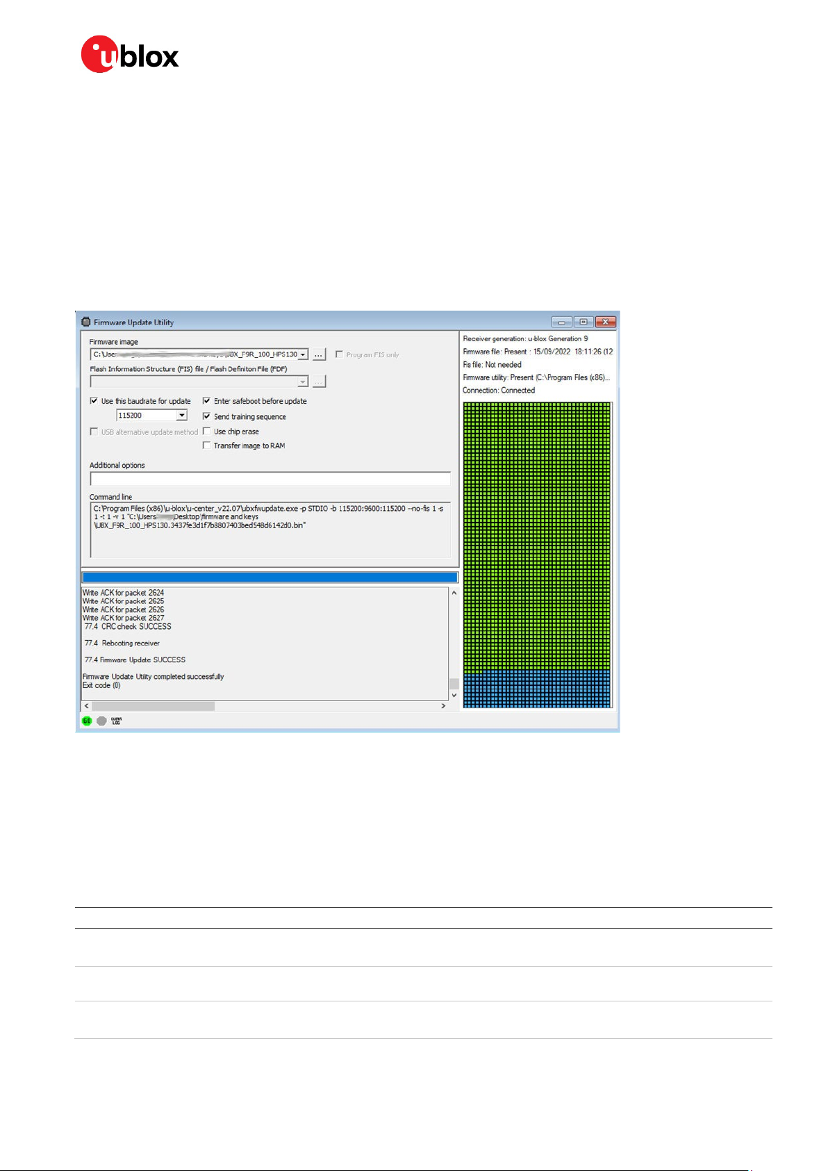
2.2 Updating the receiver firmware ............................................................................................................... 7
2.3 Storing configuration settings.................................................................................................................8
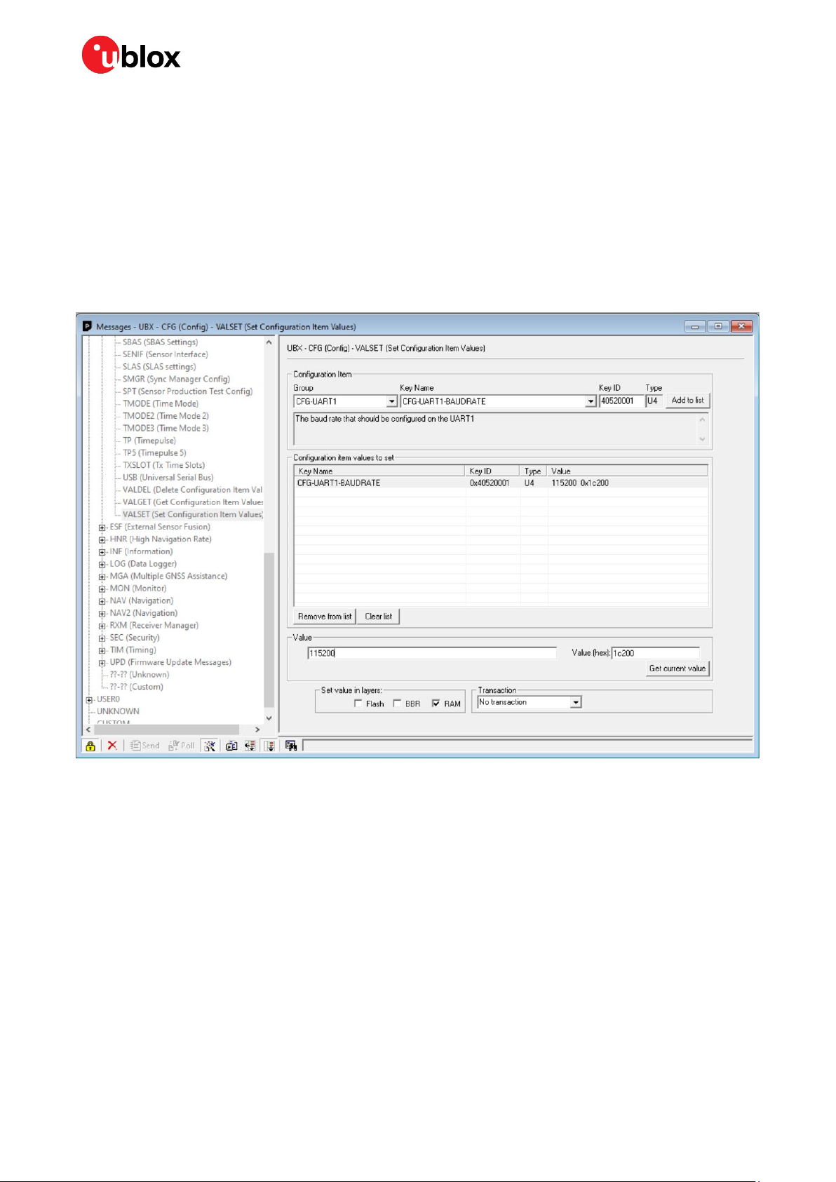
2.4 Modifying the receiver configuration in UBX-CFG-VALSET view .....................................................9
2.5 Modifying the receiver configuration in the Generation 9 Advanced Configuration view ...........9
3Installation ............................................................................................................................................ 11
3.1 Mounting the receiver ..............................................................................................................................11
3.2 Mounting the antenna .............................................................................................................................13
3.3 Connecting cables.....................................................................................................................................13
3.4 Setting up UART configuration..............................................................................................................13
4GNSS setup........................................................................................................................................... 14
4.1 Verifying GNSS signals ............................................................................................................................14
4.2 Changing enabled constellations ..........................................................................................................15
5RTK setup.............................................................................................................................................. 16
5.1 Setting up NTRIP client in u-center.......................................................................................................16
5.2 Setting up MQTT client in u-center.......................................................................................................17
5.3 Monitoring RTK status ............................................................................................................................18
6Sensor fusion setup ........................................................................................................................... 19
6.1 Providing odometer data to the receiver..............................................................................................19
6.1.1 Wheel ticks.........................................................................................................................................19
6.1.2 Speed...................................................................................................................................................19
6.1.3 Data stream quality..........................................................................................................................19
6.1.4 UBX-ESF-MEAS sample code ........................................................................................................20
6.2 Sensor fusion configuration ...................................................................................................................20
6.2.1 Dynamic platform model.................................................................................................................21
6.2.2 IMU-mount alignment .....................................................................................................................21
6.2.3 Setting up odometer configuration ..............................................................................................21
6.2.4 Navigation output rate ....................................................................................................................22
7Calibration and testing ..................................................................................................................... 23
7.1 Initialization and calibration ...................................................................................................................23

ZED-F9R - Application note
UBX-22035176 - R01 Contents Page 4 of 30
C1-Public
7.2 Preserving calibration ..............................................................................................................................24
7.3 Performing a basic test drive..................................................................................................................24
7.4 Scenario testing ........................................................................................................................................24
AAppendix................................................................................................................................................ 25
A.1 Recording logs ..................................................................................................................................... 25
A.2 Replaying logs...................................................................................................................................... 25
A.3 Interference of GNSS signals ......................................................................................................... 25
A.4 Communications and protocols..................................................................................................... 26
A.5 Basic alignment & position offset checks.................................................................................. 27
A.6 Odometry data issues ....................................................................................................................... 27
A.7 RTK never reaching fix ...................................................................................................................... 27
A.8 Dropping out of dead reckoning periodically............................................................................. 28
A.9 Troubleshooting checklist............................................................................................................... 28
Related documentation ........................................................................................................................... 30
Revision history.......................................................................................................................................... 30
Contact.......................................................................................................................................................... 30

ZED-F9R - Application note
UBX-22035176 - R01 Contents Page 5 of 30
C1-Public
1Introduction
This document acts as a getting started guide for evaluating and using the u-blox ZED-F9R module
and high-precision sensor fusion technology. The guide is written with a focus on robotic applications,
which is the platform that requires the most comprehensive receiver setup. As such, the guide is also
suitable for other platforms where the setup is more simple.
The complete setup process is divided into self-contained chapters focusing on specific parts of the
setup. The setup process includes
•preparing the host system
•configuring the receiver
•installing the receiver in a vehicle, and
•running test drives
It is strongly recommended to go through the chapters in order to make the setup process easier.
The document may contain specific information based on the product documentation such as
Integration manual [1] or Interface description [2] which are updated regularly. Please refer to the
product documentation whenever there are inconsistencies between this document and the official
product documentation. This document is intended as a beginner’s guide and does not supersede
product documentation.
1.1 Required items
The following items are required for completing the setup in this guide:
•An operational ZED-F9R module
•A suitable multiband GNSS antenna
•A host PC running u-center for F9 products
•Serial communication between the receiver and the host
•Means to provide odometer data to the receiver
•Means to provide correction data to the receiver, including access to a correction service or a base
station
•Means to properly attach the receiver to the vehicle
1.1.1 Operational ZED-F9R module
At the center of the setup is the ZED-F9R module installed on a printed circuit board (PCB). We
recommend the C102-F9R evaluation kit for first-time users, as it provides a tested, ready-to-use
device for most purposes. A custom design is also allowed, provided it follows the module’s hardware
design requirements (see [1]). The design should also provide at least a UART connection to the
receiver but having USB support is strongly recommended.
1.1.2 GNSS antenna requirements
During the evaluation phase, it is best to start with known working components and the design can
be optimized for cost, space, weight, or other considerations at a later stage. As a high-level summary,
the antenna must:
•Be capable of multi-band L1 and L2 reception
•Be an active antenna with at least 17 dB of gain
•Be designed for real-time kinematic (RTK) applications with suitable phase center variation and
group delay characteristics
•Include ground plane, if the antenna requires one

ZED-F9R - Application note
UBX-22035176 - R01 Contents Page 6 of 30
C1-Public
1.1.3 Host system
Certain functionality in the setup needs to be implemented by a host system. This includes:
•Configuring the receiver
•Monitoring and debugging the receiver
•Providing odometer data to the receiver
•Providing correction data to the receiver
All of the above can be done in u-center, except for providing odometer data to the receiver. It is
recommended to start evaluating and developing the system with a PC running u-center as the main
host, and gradually move the functionality to an embedded host for the final product.
It is also strongly recommended to make monitoring and debugging the receiver possible in the final
product. To do this, design your system so that is it possible to connect to u-center directly to the
receiver. Alternatively, data logging may be implemented by the host to allow data analysis and
debugging.
1.1.4 Odometer data
Odometer data refers to information about the distance travelled by a vehicle. This information is
usually available from a vehicle either as wheel ticks or speed measurements. The data is typically
generated by sensors that can measure the rotation of the vehicle’s wheels, such as Hall effect
sensors. These sensors are often used in low-cost brushless DC motors utilized in typical robotic
applications.
Providing odometer data to the receiver is mandatory for high-precision sensor fusion. If odometer
data is not available from the vehicle, an external sensor must be attached to the vehicle for an
accurate assessment of achievable accuracy.
Odometer data can be supplied to the receiver either through dedicated hardware pins for wheel ticks
and direction, if the application type permits it, or through a serial interface as UBX-ESF-MEAS
messages.
1.1.5 Correction data
Correction data is another mandatory part for high-precision sensor fusion. Corrections allow the
receiver to measure its position more precisely by providing more information about the available
satellites. Correction data is available through dedicated services, such as u-blox PointPerfect, that
utilize dedicated software for obtaining the data. This data then is provided to the receiver through a
serial port.

ZED-F9R - Application note
UBX-22035176 - R01 Contents Page 7 of 30
C1-Public
2Communicating with the receiver in u-center
All communication with the receiver is handled through the u-blox proprietary UBX message protocol
(see [2]). Through different messages, the user can apply configurations and monitor the status of
the receiver. u-center provides a human-machine interface for these operations. This section acts as
an introduction into communicating with the receiver in u-center. u-center is available from the u-blox
website.
2.1 Connecting the receiver with u-center
Follow these steps to connect u-center to the receiver and verify that the connection works:
1. Power on the receiver.
2. Connect the receiver to the host with a serial or USB cable.
3. Open u-center on your PC.
4. In u-center, select the correct serial port from Receiver > Connection > COMxx.
5. If connecting through UART, set the correct baudrate from Receiver > Baudrate. The default
baudrate of the ZED-F9R is 38400.
6. Open the Messages View from View > Messages View.
7. Select the UBX-MON-VER message from the left-side of the list.
8. Click Poll. The view should look like the following when the receiver is operating properly:
Figure 1: u-center UBX-MON-VER message
2.2 Updating the receiver firmware
Please update to the latest receiver firmware if the shipped ZED-F9R module has an older version. u-
blox receiver firmware binaries are available on the ZED-F9R product website.

ZED-F9R - Application note
UBX-22035176 - R01 Contents Page 8 of 30
C1-Public
The receiver firmware can be updated via the firmware update utility in u-center:
1. Open u-center and connect it to the receiver.
2. Open the firmware update utility from Tools > Firmware Update.
3. Select the target firmware image file in the Firmware image field.
4. If connected through UART, check the Use this baudrate for update box and select a higher
baudrate to make the update faster. The receiver does not need to be configured separately for
this step.
5. Press the green Go button in the bottom left corner to start the update process.
6. The receiver is ready to be used once the console output states that the update completed
successfully.
7. The new firmware version can be confirmed with the UBX-MON-VER message.
Figure 2: u-center firmware update
2.3 Storing configuration settings
ZED-F9R is fully configurable with UBX configuration interface messages. The configuration
database in the receiver's RAM holds the current configuration that is used by the receiver at run-
time. It is constructed on start-up of the receiver from several sources of configuration. The
configuration interface and the available keys are described in the F9 HPS 1.30 Interface description
[2].
Memory layer Description
RAM The configuration settings stored in RAM remain effective until power-down or reset
BBR (battery-backed RAM) The configuration settings are stored as long as the backup battery supply remains
Flash memory Permanent storage of configuration settings
Table 1 Memory layers for storing configuration settings

ZED-F9R - Application note
UBX-22035176 - R01 Contents Page 9 of 30
C1-Public
2.4 Modifying the receiver configuration in UBX-CFG-VALSET
view
Figure 3 shows the UBX-CFG-VALSET message view.
1. Select the configuration items from the Group and Key Name dropdown menus and add these to
the list of configuration items to set by clicking the Add to list button.
2. To set the value to apply, select an item from the list and set the value in the Value field.
To poll the current value of the item, click the Get current value button.
3. Select the correct memory layer(s) in the Set value in layers field.
4. Click the Send button in the bottom left corner of the window.
Figure 3: UBX-CFG-VALSET message
During the evaluation phase, it is most simple to write the configuration directly to flash. During
development and series production, it is recommended to write the configuration to the RAM or BBR
layer at startup. The host should not write to flash at every startup because of the maximum limit on
the number flash write cycles.
2.5 Modifying the receiver configuration in the Generation 9
Advanced Configuration view
Figure 4 shows the Generation 9 Advanced Configuration View. This view presents all the available
configuration items as a grouped list.
1. Add items to the list to be applied by selecting an item from the grouped list.
2. Write the correct value in the Value field.
3. Click the Set in RAM/BBR/Flash button.
4. To send the configuration to the receiver, click the Send config changes button.

ZED-F9R - Application note
UBX-22035176 - R01 Contents Page 10 of 30
C1-Public
Figure 4: Generation 9 configuration view
During the evaluation phase, it is most simple to write the configuration directly to flash. During
development and series production, it is recommended to write the configuration to the RAM or BBR
layer at startup. The host should not write to flash at every startup because of the maximum limit on
the number flash write cycles.

ZED-F9R - Application note
UBX-22035176 - R01 Contents Page 11 of 30
C1-Public
3Installation
The first step of setting up the ZED-F9R is installing it into the vehicle. Proper installation is vital for
the navigation performance of the receiver, as its internal sensors must be able to measure the
dynamics of the vehicle accurately in a consistent way. This means the antenna and receiver must be
mounted rigidly in a fixed position and orientation relative to the vehicle’s body.
Figure 5: Conceptual system view with good alignment
3.1 Mounting the receiver
Start by finding a suitable location in the vehicle to mount the receiver. The placement of the receiver
does not matter in most applications. For best performance, the receiver should be placed as close to
the center of the vehicle’s rear axle as possible. If the application’s accuracy requirements are very
demanding, an advanced configuration may be needed.
Next, plan the orientation of the receiver. Figure 6 shows the inertial measurement unit (IMU) frame
and the installation frame. The default assumption is that the x, y and z axes of the IMU frame are
parallel to the x, y, and z axes of the installation frame. The IMU frame orientation is printed on the
label of the C102-F9R evaluation kit; for custom designs refer to Figure 7. For the simplest possible
installation, mount the receiver in the orientation described above. If the receiver is mounted in any
other orientation, a custom configuration must be set for correct performance.
☞Note that the configured misalignment must be within 3 degrees of the truth to prevent
significant degradation in navigation performance. A misalignment of tens of degrees will result
in failure. Consult section 3.2.3 of the ZED-F9R Integration manual [1] for more information about
the IMU alignment. Configuring the misalignment is described in section 6.2.2.

ZED-F9R - Application note
UBX-22035176 - R01 Contents Page 12 of 30
C1-Public
Figure 6: IMU frame and installation frame
Figure 7: Orientation information. Z-axis points upwards.

ZED-F9R - Application note
UBX-22035176 - R01 Contents Page 13 of 30
C1-Public
Finally, attach the receiver rigidly to the vehicle’s frame. meaning that it must not be able to move
relative to the vehicle. This also means that the receiver must not be attached to any part of the
vehicle that is able to move. Any movement and excessive vibration will be detrimental to the
navigation performance.
3.2 Mounting the antenna
Find a suitable location for the antenna. The antenna must be placed so that is has a clear view of the
sky. For best performance, place the antenna as close to the receiver as possible.
If the antenna is an active patch antenna such as the u-blox ANN-MB, it needs a sufficient ground
plane, e.g., a metallic disc with a ~15 cm diameter.
3.3 Connecting cables
Connect all the necessary cables, i.e., power, antenna, serial communication etc. to the receiver. Verify
that the receiver is operational by repeating the procedure in 2.1
Once the serial connection to the receiver is established and verified, the installation part is complete.
3.4 Setting up UART configuration
If you are using UART as the main interface for communication, increase the receiver’s baudrate. The
default baudrate of 38400 may not be fast enough if the receiver is outputting a high number of
messages. This can lead to data loss and even a complete failure in communication.
The recommended baudrate is 115200. This can be configured with CFG-UART1-BAUDRATE. Some
applications may require even higher rates, especially if a higher navigation output rate is enabled.
The utilization of the receiver’s communication ports can be monitored with the UBX-MON-COMMS,
UBX-MON-TXBUF and UBX-MON-RXBUF messages.

ZED-F9R - Application note
UBX-22035176 - R01 Contents Page 14 of 30
C1-Public
4GNSS setup
Setting up the F9R for good GNSS performance is simple: just make sure the receiver has good quality
signals. The default configuration of the receiver firmware is suitable for most use cases and does not
need to be modified for most applications. Nevertheless, this chapter shows how to change the GNSS
constellation configuration settings in case it is needed.
4.1 Verifying GNSS signals
1. Go to a location with an open sky view.
2. Connect the receiver to u-center.
3. Wait for the receiver to reach a 3D fix.
4. Check the available satellite signals in the Satellite Level view by clicking View > Docking Windows
> Satellite Level:
Figure 8: u-center Satellite Level view
Under open sky conditions, you should have the following result:
•At least 20 signals are available
•Average CN0 value of used signals is at least 40
•Expected constellations are used
•Signals from multiple bands are available, e.g., L1 and L2 for GPS
⚠If the signal quality is bad, improve it before continuing. Bad GNSS signals will result in bad
navigation performance in all conditions. Likely reasons for poor signal quality are bad antenna,
missing ground plane and obstructed sky view.
In u-center, verify that the position is reported in the Data view by clicking View > Docking Windows
> Data.

ZED-F9R - Application note
UBX-22035176 - R01 Contents Page 15 of 30
C1-Public
Figure 9: u-center Data view
4.2 Changing enabled constellations
The enabled satellite constellations and signals are controlled by configuration items in the CFG-
SIGNAL group. A constellation is enabled when the constellation’s enable key and both the L1 and L2
band keys are set to 1. Disabling a constellation can be done by setting the constellation’s enable key
to 0.
For example:
•To disable the BeiDou constellation, set the configuration item CFG-SIGNAL-BDS_ENA to 0.
•To enable the BeiDou constellation, set the configuration items CFG-SIGNAL-BDS_ENA, CFG-
SIGNAL-BDS_B1_ENA and CFG-SIGNAL-BDS_B2_ENA to 1.

ZED-F9R - Application note
UBX-22035176 - R01 Contents Page 16 of 30
C1-Public
5RTK setup
For proper RTK performance, the receiver requires a continuous feed of correction data. It is available
from correction data providers through either NTRIP or MQTT protocols, each requiring application
software for fetching the data from the provider’s server and feeding it to the receiver through serial
ports. This chapter shows how to use both the NTRIP and MQTT client on u-center, and how to
monitor the RTK status of the receiver.
5.1 Setting up NTRIP client in u-center
There are both commercial and free NTRIP services available. For hobbyists and early prototyping, a
good option is RTK2go, a free community-driven NTRIP service where correction data streams from
other users are available for use. For production-grade applications, more robust commercial services
are recommended.
Start using the u-center NTRIP client with the following steps:
1. Open u-center and connect to the receiver via Receiver > Connection.
2. Open the NTRIP client settings from Receiver > NTRIP Client.
3. Fill in the NTRIP caster settings fields.
4. To fetch the available mount points from the service, click the Update source table button.
5. Select the correct mount point from the dropdown menu.
6. Press OK to start the NTRIP client.
Figure 10: u-center NTRIP client
The status bar at the bottom of the u-center window provides information on the status of the service
for monitoring and debugging purposes. When the authentication is successful and the service is
connected, the connection symbol turns green.
Figure 11: u-center status bar
To view more details of the NTRIP client’s operation, click the connection symbol. The NTRIP Log
window is displayed.

ZED-F9R - Application note
UBX-22035176 - R01 Contents Page 17 of 30
C1-Public
Figure 12: NTRIP client log
5.2 Setting up MQTT client in u-center
IoT devices and applications require a reliable, robust, and secure messaging protocol. That is where
MQTT comes in. MQTT is an OASIS standard messaging protocol for the Internet of Things (IoT). It is
designed as an extremely lightweight publish/subscribe messaging transport that is ideal for
connecting remote devices with a small code footprint and minimal network bandwidth. (Source:
https://mqtt.org/)
PointPerfect is a high performance GNSS augmentation service that enables high accuracy with high
precision GNSS receivers. PointPerfect adopts the industry-driven SPARTN messaging format.
SPARTN is an industry-led format that enables the highly efficient transfer of GNSS correction data.
The service uses MQTT as the basic transport mechanism for the different elements of the service.
This includes authentication, ancillary services like AssistNow, service key delivery and the actual
service. u-center implements a MQTT client.
Start using the u-center MQTT client with the following steps:
1. Open u-center and connect to the receiver via Receiver > Connection.
2. Open the MQTT client settings from Receiver > MQTT Client.
3. Download a u-center config file from the Thingstream portal associated with your device and
region of operation and add it as the “JSON config file”.
4. Check the box to “Subscribe to key topic”.
5. Check the box to “Subscribe to AssistNow topic”.
6. Check the box to “Subscribe to data topic”.
7. Select the data topic using the drop-down menu suitable for the region of operation.
8. Press OK to start the MQTT client.
For more information on the PointPerfect service, please refer to: PointPerfect getting started guide
The status bar at the bottom of the u-center window provides information on the status of the service
for monitoring and debugging purposes. When the authentication is successful and the service is
connected, the connection symbol turns green.
Figure 13: Bottom Status bar of u-center

ZED-F9R - Application note
UBX-22035176 - R01 Contents Page 18 of 30
C1-Public
To view more details of the MQTT client’s operation, click the connection symbol. The MQTT Log
window is displayed.
Figure 14: MQTT client log
5.3 Monitoring RTK status
Make sure the receiver is getting correction data by monitoring the RTK status in u-center (see Figure
15):
•In the general information view (View > Docking Windows > Data), the RTK status is shown in the
Fix status field as “Float” or “Fixed” if RTK is used.
•Alternatively, in the UBX-NAV-PVT message view, the RTK status is shown in the Carrier Range
Status field as “Float” or “Fixed” if RTK is used.
Figure 15: RTK status in u-center
Under open sky scenarios, if the receiver gets to a fixed state in less than two minutes, the receiver,
antenna and correction service are compatible and working well.

ZED-F9R - Application note
UBX-22035176 - R01 Contents Page 19 of 30
C1-Public
6Sensor fusion setup
The final and most important part of the setup is setting up the receiver for sensor fusion. The
receiver depends heavily on the internal IMU data, odometer data from the vehicle, and proper
configuration.
6.1 Providing odometer data to the receiver
As mentioned in 1.1.4, the receiver requires either wheel ticks or speed data to be supplied to it. Wheel
ticks may be sent through either the dedicated pins for wheel ticks and direction, or through a serial
interface as UBX-ESF-MEAS messages. Speed data may be sent through a serial interface only. The
rest of the chapter covers cases where the serial interface is used. Consult chapter 3.2.5 of the ZED-
F9R Integration manual [1] for a detailed description of wheel ticks and speed.
6.1.1 Wheel ticks
Wheel ticks represent the rotation of a wheel: every rotation generates a constant number of ticks.
Through the wheel tick sensor resolution (ticks per revolution) and wheel diameter, the information
can be converted into the distance travelled by the wheel.
The wheel ticks should be absolute, meaning the value starts from zero and increments regardless of
the direction of travel. The direction is indicated with its own bit in the input message.
Wheel ticks can be input from either a single source (single tick) or from both the rear-left and rear-
right wheel of a vehicle. When providing a single tick, the value should represent the vehicle’s
movement at the center of the rear axle. This can be achieved by averaging the wheel tick
measurement of both rear-wheels. Providing rear-wheel ticks is preferred whenever available. The
UBX-ESF-MEAS data types for wheel ticks are:
•single tick = 10
•rear-left wheel tick = 8
•rear-right wheel tick = 9
For optimal performance, the wheel tick resolution should be less than 5 cm, i.e., one tick should
correspond to a displacement of 5 cm.
6.1.2 Speed
Speed is input as a signed value in millimeters per second. The UBX-ESF-MEAS data type for speed is
11.
6.1.3 Data stream quality
When sending odometer data with UBX-ESF-MEAS messages, ensure that the data stream is of good
quality. For optimal performance:
•Supply odometer data at a rate of 10 Hz.
•Send data at even intervals, e.g., every 100 ms for 10 Hz input.
•Data must be sent with delay less than 10 % of the sampling interval.
•Data loss must be less than 1 %.
•Give odometer data priority over other communication with the receiver. If the odometer data
stream is being hampered by other data, a separate serial port may be used.
•Use the highest baudrate available to minimize the latency caused by transmission.

ZED-F9R - Application note
UBX-22035176 - R01 Contents Page 20 of 30
C1-Public
6.1.4 UBX-ESF-MEAS sample code
u-blox has collaborated with the OpenMower project to provide an example of integrating the ZED-
F9R in a robotic application. The u-blox driver source code can be found here.
In the OpenMower project, wheel ticks from two individual wheels are provided to the receiver. The
data is sent to the receiver with the GpsInterface::send_wheel_ticks function. The function takes in
the sensor timestamp, and the direction and wheel tick value from the two wheels. These are put into
an array, together with the UBX-ESF-MEAS message class and identifier bytes. Next, the
GpsInterface::send_packet function completes the message with the two-byte UBX protocol header
in the beginning and the two-byte checksum in the end. The complete message is sent to the receiver
with the GpsInterface::send_raw function.
When wheel tick messages are being delivered to the receiver, use the UBX-ESF-MEAS graph view in
u-center to monitor the wheel tick data. The graphs below show two systems. In the top picture the
wheel ticks are combined into a single tick with CFG-SFODO-COMBINE_TICKS = 1. In the bottom
picture both left and right wheel ticks are being used. Both pictures show the vehicle moving at a
constant velocity.
Figure 16: u-center UBX-ESF-MEAS graph view of single tick (top) and left/right (bottom) wheel tick systems
6.2 Sensor fusion configuration
The sensor fusion configuration of the receiver depends on several different aspects of the entire
setup, including the used vehicle, how the receiver is mounted on the vehicle, and what type of
odometer data is used. Thus, the configuration needs to be modified if the setup is changed.
Other manuals for ZED-F9R
2
Table of contents