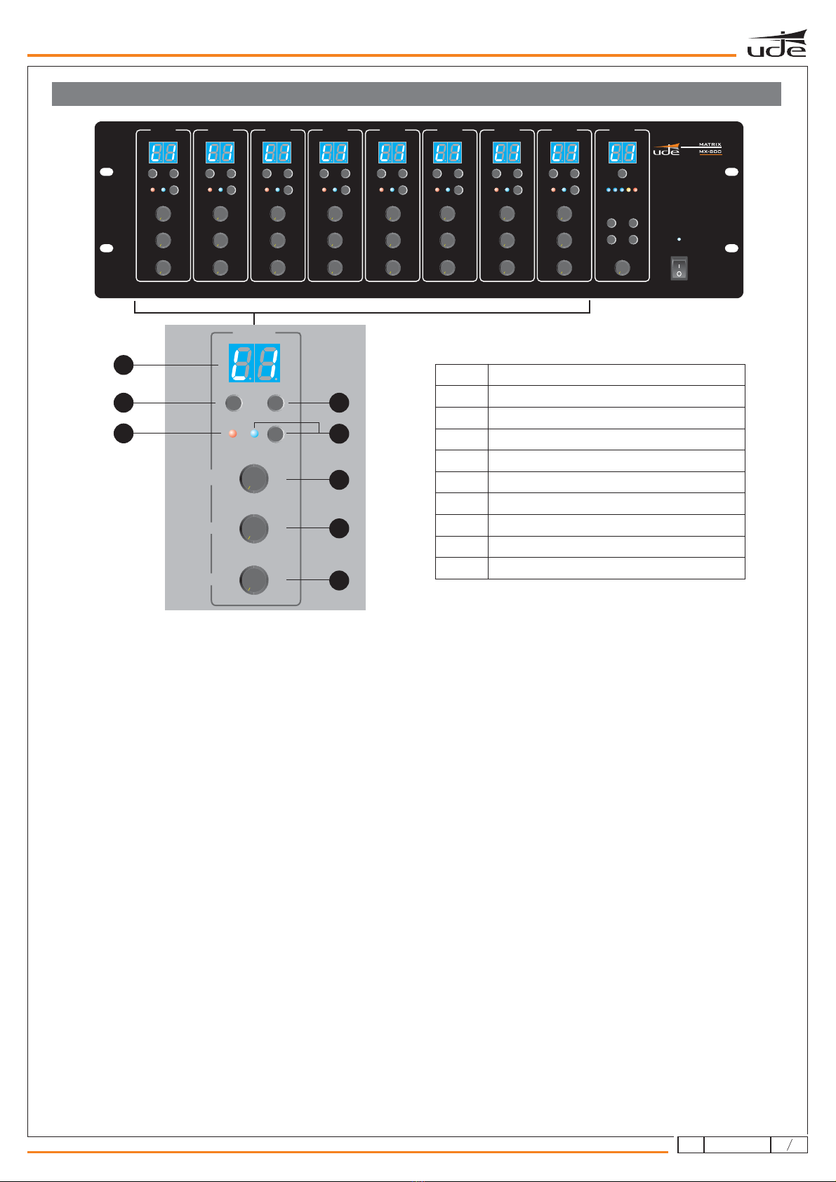
MUSIC MUSIC MUSIC MUSIC MUSIC MUSIC MUSIC MUSIC
MASTER MASTER MASTER MASTER MASTER MASTER MASTER MASTER
MIC1 MIC1 MIC1 MIC1 MIC1 MIC1 MIC1 MIC1
2
2
2
3
3
3
4
4
4
5
5
5
0
0
0
1
1
1
6
6
6
7
7
7
8
8
8
10
10
10
9
9
9
SOURCE UP SOURCE UP SOURCE UP SOURCE UP SOURCE UP SOURCE UP SOURCE UP SOURCE UPSOURCE DOWN SOURCE DOWN SOURCE DOWN SOURCE DOWN SOURCE DOWN SOURCE DOWN SOURCE DOWN SOURCE DOWN
PAGE BUSY PAGE BUSY PAGE BUSY PAGE BUSY PAGE BUSY PAGE BUSY PAGE BUSY PAGE BUSYMIC1 MIC1 MIC1 MIC1 MIC1 MIC1 MIC1 MIC1
PRIORITY PRIORITY PRIORITY PRIORITY PRIORITY PRIORITY PRIORITY PRIORITY
2
2
2
3
3
3
4
4
4
555 55 55
5
5
0
0
0
1
1
1
6
6
6
7
7
7
8
8
8
10
10
10
9
9
9
2
2
2
3
3
3
4
4
4
5
5
5
0
0
0
1
1
1
6
6
6
7
7
7
8
8
8
10
10
10
9
9
9
2
2
2
3
3
3
4
4
4
5
5
5
0
0
0
1
1
1
6
6
6
7
7
7
8
8
8
10
10
10
9
9
9
2
2
2
3
3
3
4
4
4
5
5
5
0
0
0
1
1
1
6
6
6
7
7
7
8
8
8
10
10
10
9
9
9
2
2
2
3
3
3
4
4
4
5
5
5
0
0
0
1
1
1
6
6
6
7
7
7
8
8
8
10
10
10
9
9
9
2
2
2
3
3
3
4
4
4
5
5
5
0
0
0
1
1
1
6
6
6
7
7
7
8
8
8
10
10
10
9
9
9
2
2
2
3
3
3
4
4
4
5
5
5
0
0
0
1
1
1
6
6
6
7
7
7
8
8
8
10
10
10
9
9
9
ZONE 1 ZONE 8ZONE 2 ZONE 3 ZONE 4 ZONE 5 ZONE 6 ZONE 7
ZONE SELECT
OUTPUT LEVEL
FUNCTION
ENTER BGM ALL
PAGE ALL
ESC
MONITOR
2
3
45
0
1
6
7
8
10
9
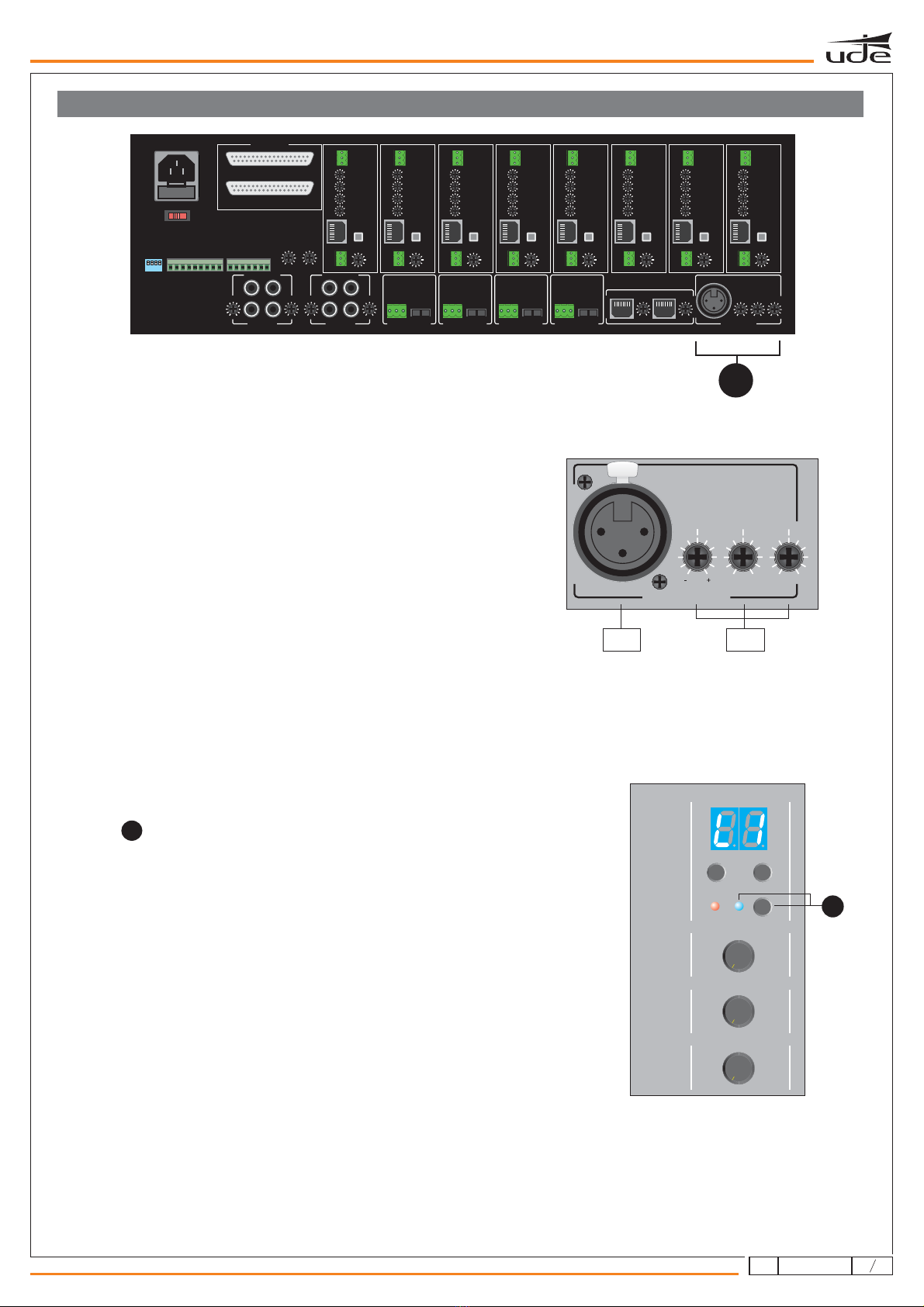
EMERGENCY
MICROPHONE 1
ZONE
8
ZONE
2
ZONE
3
ZONE
4
ZONE
5
ZONE
6
ZONE
7
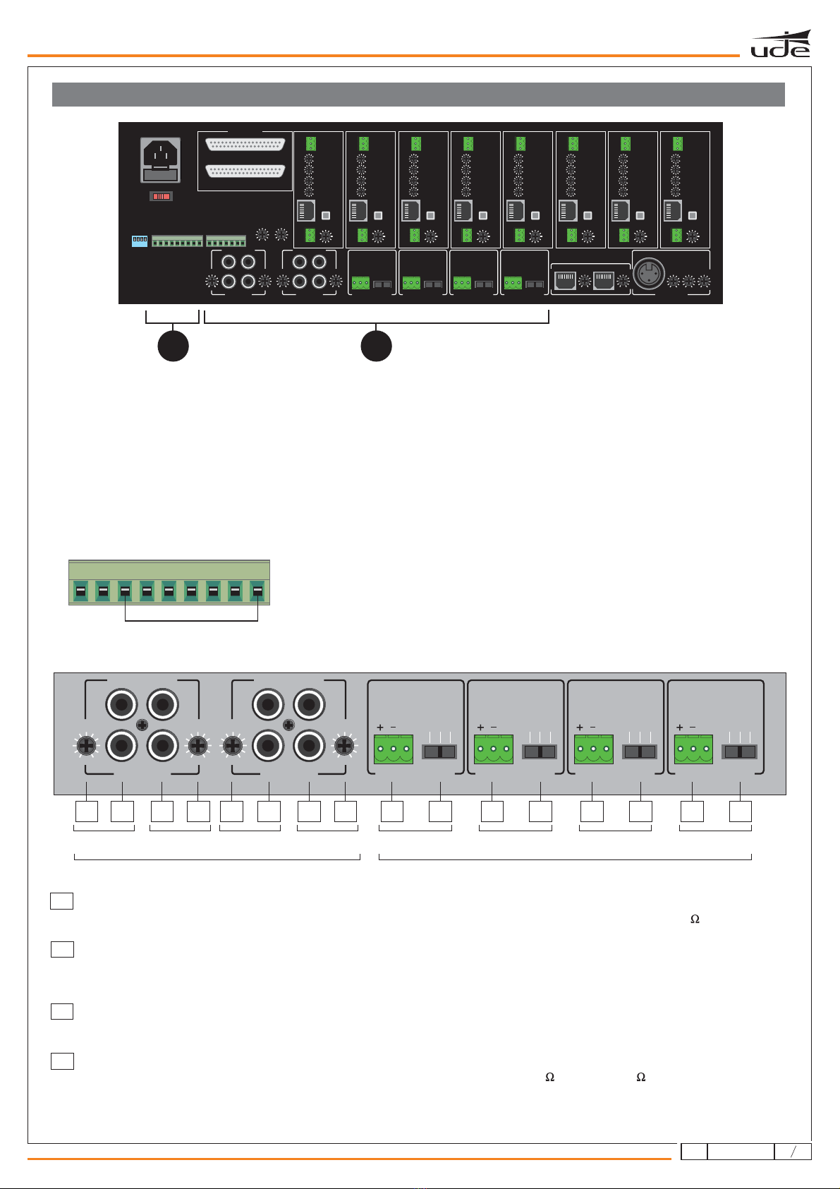
PAGING MIC1 PAGING MIC2
MIC 5mV / LINE 300mVMIC 5mV / LINE 300mVMIC 5mV / LINE 300mVMIC 5mV / LINE 300mV 5mV-300mV / 680Ω
SLAVE1
MASTER
SLAVE2
SLAVE3
dB dB
+
-
+
-
LINE 1 LINE 2
+ +
dB dB
GAIN GAIN
R
L
R
L
195mV-2V/47KΩ
- -
LINE 3 LINE 4 LINE 8LINE 7LINE 6LINE 5
+ +
dB dB
GAIN GAIN
R
L
R
L
195mV-2V/47KΩ
- -
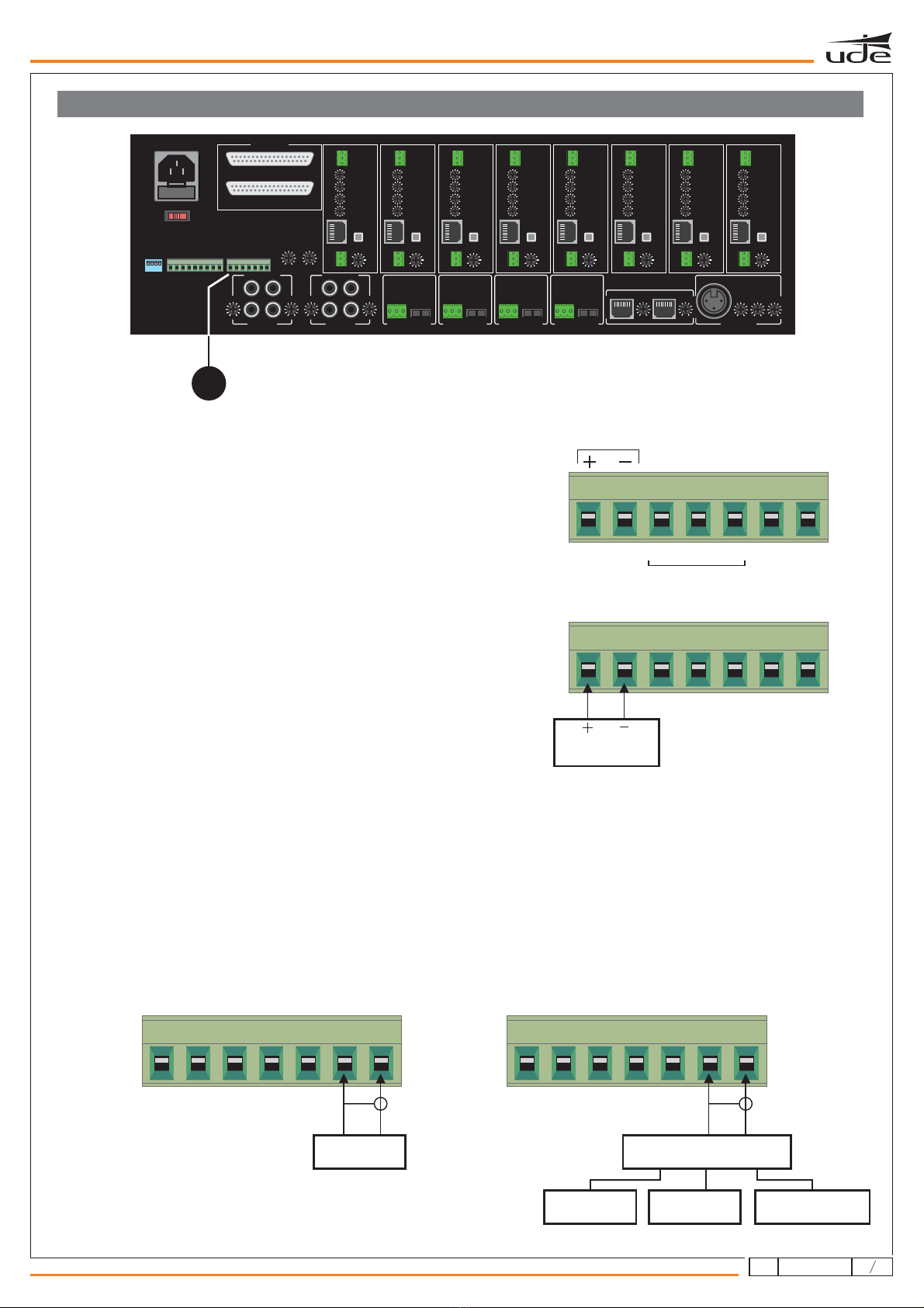
12345678G
CONTACT CLOSURE
FIRE ALARM
+
dB
GAIN
-+
dB
GAIN
-+
dB
LF
-+
dB
HF
-
+
dB
GAIN
-
COMMON
ALERT
EVAC
GROUND
EMC IN
+24V D C
GROUND
775mV/10KΩ
ZONE
1
-
+
dB
GAIN
REMOTE
WALL CONTROL
HF
LF
0V 1
+3
-
2
PAG E
GAIN
-10
+10
dB
-10
+10
dB
+3
dB
-
+
OUTPUT
DISABLE
ENABLE
GGGG
REMOTE SOURCE 1
0V 1
-
2
300mV-1.1V/10KΩ
dB
-
+
-
+
dB
GAIN
REMOTE
WALL CONTROL
HF
LF
0V 1
+3
-
2
PAG E
GAIN
-10
+10
dB
-10
+10
dB
+3
dB
-
+
OUTPUT
DISABLE
ENABLE
REMOTE SOURCE 1
0V 1
-
2
300mV-1.1V/10KΩ
dB
-
+
-
+
dB
GAIN
REMOTE
WALL CONTROL
HF
LF
0V 1
+3
-
2
PAG E
GAIN
-10
+10
dB
-10
+10
dB
+3
dB
-
+
OUTPUT
DISABLE
ENABLE
REMOTE SOURCE 1
0V 1
-
2
300mV-1.1V/10KΩ
dB
-
+
-
+
dB
GAIN
REMOTE
WALL CONTROL
HF
LF
0V 1
+3
-
2
PAG E
GAIN
-10
+10
dB
-10
+10
dB
+3
dB
-
+
OUTPUT
DISABLE
ENABLE
REMOTE SOURCE 1
0V 1
-
2
300mV-1.1V/10KΩ
dB
-
+
-
+
dB
GAIN
REMOTE
WALL CONTROL
HF
LF
0V 1
+3
-
2
PAG E
GAIN
-10
+10
dB
-10
+10
dB
+3
dB
-
+
OUTPUT
DISABLE
ENABLE
REMOTE SOURCE 1
0V 1
-
2
300mV-1.1V/10KΩ
dB
-
+
-
+
dB
GAIN
REMOTE
WALL CONTROL
HF
LF
0V 1
+3
-
2
PAG E
GAIN
-10
+10
dB
-10
+10
dB
+3
dB
-
+
OUTPUT
DISABLE
ENABLE
REMOTE SOURCE 1
0V 1
-
2
300mV-1.1V/10KΩ
dB
-
+
-
+
dB
GAIN
REMOTE
WALL CONTROL
HF
LF
0V 1
+3
-
2
PAG E
GAIN
-10
+10
dB
-10
+10
dB
+3
dB
-
+
OUTPUT
DISABLE
ENABLE
REMOTE SOURCE 1
0V 1
-
2
300mV-1.1V/10KΩ
dB
-
+
-
+
dB
GAIN
REMOTE
WALL CONTROL
HF
LF
0V 1
+3
-
2
PAG E
GAIN
-10
+10
dB
-10
+10
dB
+3
dB
-
+
OUTPUT
DISABLE
ENABLE
REMOTE SOURCE 1
0V 1
-
2
1,5V/600Ω1,5V/600Ω1,5V/600Ω1,5V/600Ω1,5V/600Ω1,5V/600Ω1,5V/600Ω1,5V/600Ω
300mV-1.1V/10KΩ
dB
-
+
EMC
INPUTOUTPUT
TONE
EXTENSION LINK
LINK IN
LINK OUT
MIC
MIC
MIC
MIC
PHANTOM
PHANTOM
PHANTOM
PHANTOM
LINE
LINE
LINE
LINE
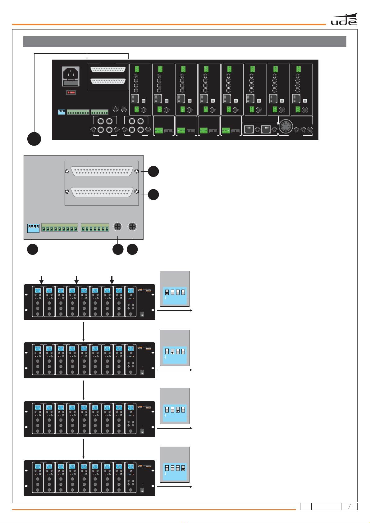
The audio matrix allows the connection of up to 8 inputs
MIC/LINE, 8 remote control panels MX-888, 2 paging desks MX-801 and
one microphone input for emergency (MIC1). All these inputs can be
routed to 8 different zones simultaneously.
The routing of up to 8 inputs to 32 zones (using an interconnected system
of 4 matrix MX-800), provides solutions for basic installations as well as
others with more advanced configuration.
By using the paging desk MX-801, it allows to page zone wise as well as
to all zones. The matrix allows the connection of up to 2 paging desks.
The remote control panels MX-888 are connected to the matrix using an
FTP shielded cable in order to send the RS-485 communication, audio
and 24VDC power supply.
For evacuation applications, the matrix includes 8 relay input contacts to
integrate with the fire alarm system. This allows to send an alarm or
evacuation message to the room or zone where the emergency is
occurring. The matrix includes an input with maximum priority in order to
broadcast a pre-recorded message (evacuation) to all zones.
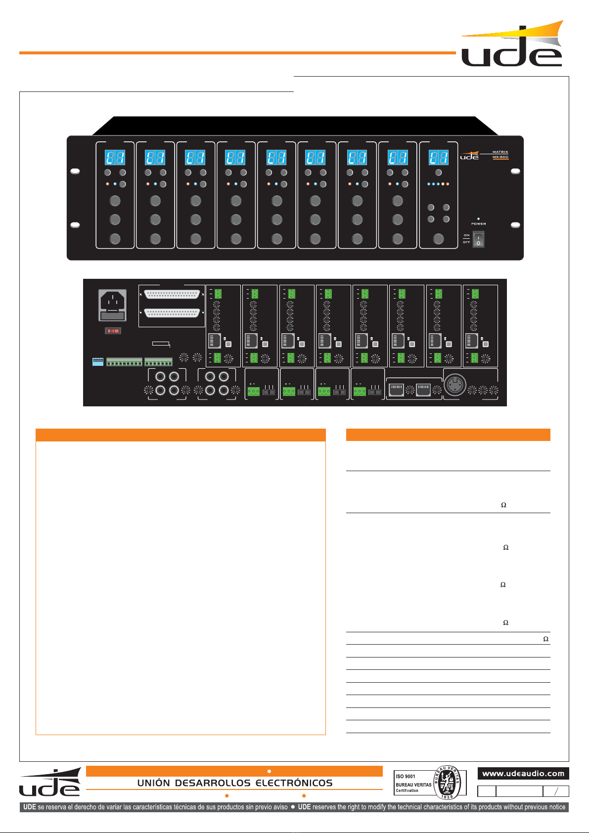
The audio matrix MX-800 allows an easy installation and a simple
management thanks to its user interface. Its management, with a focus
towards the excellence of the acoustic performance, allows it to be used
in multiple applications:
Offices, conference halls, sport centers, malls,
train stations, hotels, and airports; among others. ....
MX-800
DESCRIPTION
Microphone 1:
Weigth:
Auxiliary DC power supply:
Consumption:
Communication port:
Communication protocol:
Frequency response:
6 Kg.
24VDC.
20 W.
RJ-45
RS-485
LINE 20Hz - 20kHz (± 3dB)
MIC 80Hz - 18kHz (± 3dB)
Inputs 1 - 2 - 3 - 4 LINE (RCA):
Audio outputs 1 - 2 - 3 - 4 - 5 - 6 - 7 - 8 (Euroblock):
Inputs 5 - 6 - 7- 8 MIC/ LINE Configuration (Euroblock):
sensitivity = 195 mV - 2 V.
impedance = 47 K .
sensitivity = 1.5 V.
impedance = 600 .
sensitivity = 5 mV.
impedance = 600 .
phantom supply= 48 VDC.
5mV / 350mV / 600 .
LINE:
LINE:
Balanced:
MIC:
sensitivity = 350 mV.
impedance = 10 K .
TECHNICAL FEATURES
AC power supply: 115 / 230VAC / 50-60 Hz.
MX-800
AUDIO MATRIX
8 AUDIO INPUTS / 8 AUDIO OUTPUTS
Dimensions: 484 x 400 x 132 mm.
121
610.387A
rev.2
EQUIPOS Y SISTEMAS MEGAFONÍA / INTERCOM PUBLIC ADDRESS SYSTEMS
Tel.: +34 934 772 854 / +34 609 914 787