UE Systems UltraTrak 850S User manual

UltraTrak 850S
Smart Analog Sensor

2
Copyright
© 2021 by UE Systems. All rights reserved.
Nopartofthispublicationmaybereproduced,transmitted,transcribed,
storedinaretrievalsystem,ortranslatedintoany languagein any form by
anymeans without the written permission ofUE Systems.
Disclaimer
This manual is provided for informational purposes. UE Systems MAKES
NO WARRANTY OF ANY KIND WITH REGARD TO THIS MATERIAL,
INCLUDING, BUT NOT LIMITED TO,THE IMPLIED WARRANTIES OF
MERCHANTABILITY ANDFITNESSFOR A PARTICULAR PURPOSE.
UE Systemsshallnotbeliableforerrors,omissions,orinconsistenciesthat
maybecontainedhereinorforincidentalor consequentialdamagesin
connectionwiththefurnishing,performance,oruseofthismaterial.
Informationinthisdocumentis subjecttochangewithoutnoticeanddoes
notrepresentacommitmentonthepartofUE Systems.Theinformationin
thismanualis not all-inclusive andcannot cover all unique situations.
Patents
The product(s) described in this manual may be covered under existing
and pending patents.

3
Table of Contents
Safety Notes .................................................................................................................. 4
Getting Started .............................................................................................................. 5
1.1 Product Overview...................................................................................................5
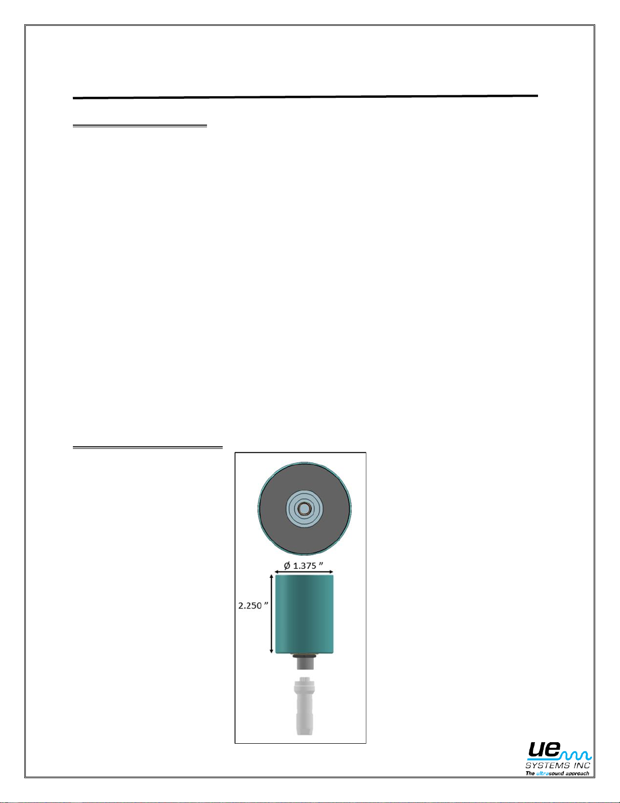
1.2 Product Dimensions...............................................................................................5
1.3 Product Specifications............................................................................................6
1.4 Product Operation..................................................................................................6
1.4.1 Power Requirements...................................................................................6
1.4.2 Sensitivity Control........................................................................................6
1.4.3 Wiring Connections .....................................................................................7
1.4.4 Current Output and Power Supply Current Draw......................................... 7
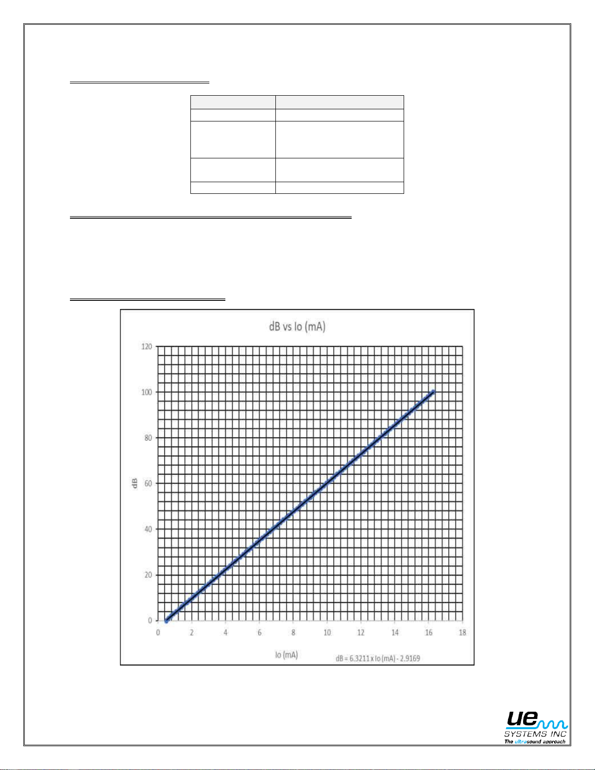
1.4.5 Typical Transfer Curve ................................................................................7
1.5 Common Applications............................................................................................8
1.5.1 Bearing Condition Monitoring and Lubrication.............................................8
1.5.2 Valve and Steam Trap Monitoring...............................................................9
1.6 Ultrasound Technology........................................................................................ 10
Sensor Placement and Installation............................................................................ 11
2.1 Primary Considerations........................................................................................ 11
2.2 Additional Considerations .................................................................................... 12
2.3 Proper Mounting................................................................................................... 12
2.4 Mounting Options................................................................................................. 13
2.4.1 Adhesive Stud Mount ................................................................................ 13
2.4.2 Fin Mount................................................................................................... 13
2.5 Accessories.......................................................................................................... 14
Customer Support....................................................................................................... 15

4
IMPORTANT SAFETY INFORMATION
READ ALL INSTRUCTIONS BEFORE USE
For your safety, the information in this manual must be followed to minimize
the risk of fire, explosion, electric shock, and to prevent property damage, personal injury, or
death.
Improper use of your ultrasonic detector may result in death or serious injury. Observe all safety
precautions. Do not attempt to make any repairs or adjustments while the equipment is operating.
Be sure to turn off and LOCK OUT all electrical and mechanical sources before performing any
corrective maintenance. Always refer to local guidelines for appropriate lockout and maintenance
procedures.

5
Getting Started
1.1 Product Overview
About The 850S
The 850s is a modern ultrasound sensor and transmitter with state-of-the-art onboard data processing
designed to detect early onset failures in industrial equipment. The 850s works in tandem with existing
plant automation and measurement applications, providing the hardware required to detect changes in
ultrasonic amplitude resulting from the degradation of equipment. The 850s can be used for a wide range
of applications, including ultrasound condition-based lubrication, bearing fault detection, valve leakage
and steam trap issues with your existing measurement systems.
Quick Facts
1. Continuously monitors friction, impacting and turbulence.
2. Connects to existing monitoring systems (PLC, SCADA, DCS, etc.).
3. Issues automated warnings in the event of bearing or lubrication failure.
4. Identifies steam trap issues and valve leakage
5. Includes patented Auto-Sensitivity Adjustment
Why invest in the 850S?
The 850s gives maintenance and reliability teams an easy way to incorporate the power of Ultrasound
into their existing monitoring technology.
The sensors can be installed and connected within 10 minutes –giving teams a reliable and ultra-fast
way to start analyzing trends and making better sense of their application.
1.2 Product Dimensions

6
1.3 Product Specifications
Sensor Parameter
Parameter Description
Power Supply Voltage
23 VDC to 26 VDC
Power Supply Current Draw
30mA DC Max, Typical
Current Output Type
Milliamp DC, Demodulated/Heterodyned
Current Output Response
Linear, Proportional to 0 dB to 100 dB of Change in Detected
Ultrasonic Signal
Current Output Range
0.500 mA DC to 16.280 mA DC @ 0.158 mA/dB of Change
in Detected Ultrasonic Signal (Typical)
Current Output Compliance Voltage
3.3 VDC
dB Output Transfer Function
dB Output = + 6.321 x (Current Output Reading), mA DC -
2.917 Db
Current Output Accuracy
Less Than ±1 dB of Reading, Typical
Ambient Operating Temperature Range
Standard Range = -20 °C to +60 °C
Extended Range = -30 °C to +80 °C
(Requires High Temp Cable)
Δ Current Output (Temperature)
+2 dB @ - 20 °C
-2 dB @ +60 °C
+3 dB @ -30 °C
-4 dB @ +80 °C
Sensitivity Adjustment
Automatic, Thru the 0 dB to 100 dB Output Range
Connection Cable
3 Wire with Shield, Removable
Cable lengths
3 meters (10 ft.)
10 meters (33 ft.)
20 meters (66 ft.)
30 meters (100 ft.)
Cable/Housing Connector
Harsh Environment, Meets or Exceeds IP67 and NEMA 6P
Cable/Housing Shielding
RF Shielded
Housing
Stainless Steel, Water Resistant and Dust Proof, Meets IP67
and NEMA 6P
Transducer
Piezoelectric
Method of Attachment
10/32 UNF Mounting Hole
Firmware
Upgradable
*Note: Specifications are subject to change without notice.
1.4 Product Operation
1.4.1 Power Requirements
The UE 850S requires a 23 to 26 V, DC power source @ 30 mA total. The power connections are to be
made via the cable connections on the sensor (refer to the connection diagram below). Note: The sensor
requires +23 VDC Minimum at the sensor after any voltage drops in the power supply loop.
1.4.2 Sensitivity Control
The UE 850S features automatic sensitivity control. The 850S adjusts sensitivity automatically which
gives the 850S hands-free measurement range of 100dB. Simply connect the sensor to a monitoring
stud/point, connect power, ground/shield, and current output to their appropriate connections.

7
1.4.3 Wiring Connections
Wire Colour
Function
Black
Ground
Red
Power Supply (V_supply)
+24 VDC Nominal
+23 to +26 Typical
Clear
Current Output
16.3 mA Max
Green
RF Shield
1.4.4 Current Output & Power Supply Current Draw
The 850S’s quiescent power supply current draw is approximately 12mA. In sensing mode add the
current output to the quiescent power supply current draw to obtain the operational power supply current
draw (30mA maximum typical).
1.4.5 Typical Transfer Curve

8
1.5 Common Applications
Ultrasound provides a mechanism for detecting
early warnings of bearing or lubrication failure. The
850s’ patented Auto-Sensitivity Adjustment feature
enables users to automatically tune into bearing
sound and clearly identify lubrication and health
issues at speeds as low as 1 RPM.
60%-80% of bearing failures are lubrication-related.
The 850s creates the ability to quickly Identify a
lack of lubrication and prevent over lubrication by
providing real-time bearing friction data while
greasing is being performed.
There are ultrasonic components in practically all forms of friction. As an example, if one were to rub the
sensor probe with a finger, an ultrasonic signal will be generated. Although there might be some audible
components to this friction, the sensor will only sense the ultrasonic components which, in this example,
will be considered a gross signal that is also amplified. In fact, due to the comparative low amplitude
nature of ultrasound, amplification is a very important feature.
Although there are obvious audible sounds emitted by most operating equipment, is the ultrasonic
elements of the acoustic emissions that are generally the most important. Ultrasound offers a predictable
diagnostic capacity. When changes begin to occur in the ultrasonic range, there is still time to plan
appropriate maintenance. According to NASA research, when a bearing enters the beginning
stages of failure, there is an amplitude increase of from 12 to 50 times over a set baseline. Not only can
the early stage of bearing failure be monitored and detected, but other warning signs can also be noted
such as: lack of lubrication, early failure, and catastrophic failure.
The levels of change are as follows:
Alarm Indication
dB Value
Alarm 1: Requires Lubrication
Baseline + 8 dB
Alarm 2: Early Onset of Bearing Failure
Baseline + 16 dB
Alarm 3: Catastrophic Bearing Failure
Baseline + 35 dB
Bearing Condition Monitoring & Lubrication

9
When valves or steam traps leak or fail, it can be extremely costly in terms of product quality, safety, and
energy loss. The 850s Auto-Sensitivity Adjustment feature enables users to automatically tune into the
trap sound and clearly identify leaking or blowing traps and valves.
Cavitation
As air enters a valve or pump, the dynamics of the pressure within can create cavitation: the forming and
explosion of bubbles. Although cavitation may be present, it does not necessarily create a problem. It
becomes a maintenance problem only when the process increases to produce conditions that will cause
internal damage. By setting a baseline, the increase in cavitation activity can be monitored to a point
where an alarm can be set, and preventive measures can be taken.
Monitoring: Flow/No flow & Leakage
Valves control fluid flow. Whether the valve’s function is to provide a simple flow/no flow operation (on/off)
or to regulate the amount of flow, a malfunction can be critical. Changes in amplitude related to these
conditions can be monitored and alarm levels may be set to note or control these changes.
When leak occurs, the fluid will move from high pressure (upstream), through the valve seat, to the low
pressure (downstream) side. As it reaches the low-pressure side, it expands briefly, producing a turbulent
flow. This turbulence has strong ultrasound components. The amplitude of the turbulence is related to a
few basics:
1. Fluid Viscosity
Under identical environments, pressures, leak size, etc.; a lighter fluid, such as air will produce more
turbulence than a heavier fluid, such as oil.
Inspect and Type of
Steam Trap & Valve
Inverted bucket,
thermostatic,
thermodynamic, float &
thermostatic traps, and
one-way valves.
Emphasis on Safety
Avoid the dangers of
failing steam traps -
water hammer can cause
serious damage to your
equipment & people
Process Efficiency &
Cost Reduction
Maintain correct
temperatures in your
process and preserve
the lifespan
of condensate return
lines (water in
pipes will cause rusting).
1.5 Common Applications
Valve and Steam Trap Monitoring

10
2. Orifice Size
The more the restriction of a fluid, less amplitude generated. A smaller diameter hole will not produce as
much sound as a larger hole under similar flow conditions.
3. Pressure Differential
Given identical leak sizes, when there is a greater pressure difference between the upstream and
downstream sides, the leak with the greater difference will produce a louder signal.
1.6 Ultrasound Technology
The Ultrasound Technology utilized by this system is generally referred to as “Airborne Ultrasound”.
Airborne Ultrasound is concerned with the transmission and reception of ultrasound signals through the
atmosphere without the need of sound conductive interface gels. It incorporates methods of receiving
signals generated through one or more media via wave signals. When it is used to detect/monitor
problems within a specific media, the technology may be referred to as Airborne/ Structure borne
Ultrasound (A/B Ultrasound).
A/B Ultrasound is concerned with sound waves that occur above human perception. The normal “audible”
environment in which the human ear is capable of sensing is 20 Hertz to 20 kHz (1,000 Hertz is 1
kilohertz or 1 kHz). The average threshold of human perception is 16.5 kHz. These audible wavelengths
range in size from as small as 3/4 inch (1.9 cm) to as large as 56 feet (17 m). The frequencies sensed by
airborne ultrasound instruments are above 20 kHz to 100 kHz. The wavelengths are magnitudes smaller
than the audible, ranging from 1/8 inch (0.3 cm) to 5.8 inch (1.6 cm). The short-wave nature of the
ultrasonic signal provides many advantages over lower frequencies.
Advantages:
1. High frequency amplitudes drop off quickly as they move from the source
of emission.
2. The signals tend to radiate in straight paths providing relative ease of
detection.
3. Since the signal strength diminishes rapidly, the sound source is easily
separated from background noise.
4. Subtle changes are detected before a major failure occurs.

11
Sensor Placement and Installation
2.1 Primary Considerations
Bearing Proximity
Place the sensor directly on the machine housing as close as possible to where the bearing is located for
the most direct path of sound and vibration transmission. Placing the sensor as close as possible to the
centerline of the bearing can also be considered to further optimize the signal coming directly from the
bearings and avoid any potential distortion.
This sensor is placed on the protective
cover and should not be used. It should be
moved to a location on the machine
housing that would allow for the most
direct path of sound transmission from the
bearing to the sensor.
Both sensors are mount vertically but the
right sensor is not mounted as close as
possible to the bearing and should not be
used. The left sensor on the other hand is
mounted in an acceptable location on the
machine housing that is closest to the
bearing.
Both sensors are placed in locations
furthest away from the centerline of the
bearing and are not optimal for data
collection
Both sensors are placed directly in line
with the center of the bearing and are the
shortest distanceto it. Both the horizontal
and vertical locations areacceptable, and
either location can be used.
PROTECTIVE
COVER

12
The sensor is placed at a location with debris that is not
allowing the sensor to fully contact that machine housing
and/or firmly attach to it. The surface should be cleaned
of all debris before placing the sensor to ensure there is
instability or weakness in the readings coming from the
bearing.
Whenever possible the sensor should be
placed in locations that best isolate it from
other sounds, both internal and external to
the machine, that could hamper consistent
monitoring of the bearing. A common
example would be the increased electrical
related sounds that can be heard the closer
the sensor is placed to an electric motor’s
wire termination junction box.
The region of the bearing that is involved in
the load transmission is referred to as the
load zone. This area can potentially yield the
highest readings, but it is often not feasible
for most machine types.
The sensor is placed at a location where it has limited
surface contact area and is prone to rocking and
movement side to side. This lack of stability will cause
the readings to be inconsistent and potentially
erroneous in nature and should not be used.
*Image showing the bearing load zone for a typical radial load on a horizontally mounted machine.
Load zone (≈150°)
Will enter the
150°
DEBRIS
2.2 Additional Considerations
Competing Sounds
Bearing Load Zone
2.3 Proper Mounting
Ensure the sensor can be firmly attached to the machine housing and is free of debris and obstructions
that would impede its ability to maintain consistent and stable contact. Eliminating any contact with the
sensor housing by structures external to the test location should also be considered.
*Image showing an electric motor’s wire termination junction box

13
2.4 Mounting Options
2.4.1 Recommended: Adhesive Stud Mount
2.4.2 Alternative: Fin Mount
When a good spot to mount the sensor is not available, UE systems’ Motor Fin Mounts may be the
perfect solution. selecting the proper Motor Fin Mount is accomplished by measuring the depth and
width of the cooling fins where you want to locate the remote ultrasound sensor. The Motor Fin Mount
needs to be long enough to directly contact the motor case between the fins. Loctite AA H3300
adhesive is then used to hold the Motor Fin Mount in place. The thickness of the Motor Fin Mount
should allow contact at the bottom and minimize the amount of adhesive needed.
oPrepare the mounting surface.
oMix the 2-part epoxy included with the kit and apply.
oPress on the plastic piece of the mounting kit until it clicks.
oWait 10 –15 minutes.
oRemove the plastic mounting kit from the stud.
oThread the sensor onto the stud.

14
2.5 Accessories
Looking For More?
UE Systems offers a variety of accessories to accommodate all your application needs!
Thermo Isolation Yoke
Mounting kit for thermal isolation.
Used in application where mounting location is above the rated temperature of the sensor. The thermo
isolation yoke uses the ambient air to significantly reduce the temperature to the sensor.
Table of contents
Popular Accessories manuals by other brands

LocknCharge
LocknCharge UVone LNC8200 Let's get started

TAG Heuer
TAG Heuer HL 2-35 user manual

Pepperl+Fuchs
Pepperl+Fuchs NBN4-12GS40-Z4L-V1-3G-3D instruction manual

Tekkeon
Tekkeon TekCharge MP2250 user guide

Measurement Systems International
Measurement Systems International MSI 9750 quick start guide

Panther
Panther TTS-160 quick start guide

SilentCall
SilentCall MEDALLION DB2-MC Installation and operating instructions

SCX Design
SCX Design P17/32477 instruction manual

American Standard
American Standard Acrylux Corner Shower Door H186 Product features

Panasonic
Panasonic AMGU4241 installation instructions

ETI
ETI NETCOM ADH Assembly Replacement Procedure

AirTest
AirTest TR-1000 Operation & maintenance manual