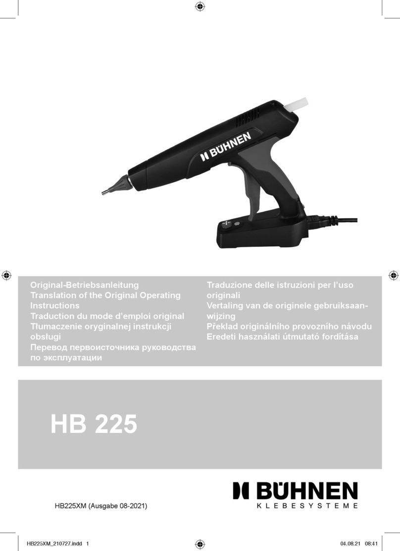
UES HP 07 User manual

HP 07
Hand Gun
Operating Manual
HP 07 PR


HP 07 Operating Manual
3
UES AG · Roemerstraße 15 · D-47809 Krefeld
Tel.: +49 (0)2151-72950 · Fax: +49 (0)2151-7295578 · info@ues-int.net · www.ues-int.net
Inhalt
Introduction....................................................................................................................................................... 4
Safety instructions ............................................................................................................................................ 5
Safety precautions regarding the glue....................................................................................................................................5
Safety precautions relating to the production machine...................................................................................................5
Safety symbols.................................................................................................................................................................................6
Technical description......................................................................................................................................... 7
Introduction.....................................................................................................................................................................................7
Putting into operation ...................................................................................................................................... 8
Check ..................................................................................................................................................................................................8
Hydraulic connections..................................................................................................................................................................8
Release stop......................................................................................................................................................................................9
Start off the system........................................................................................................................................................................9
Handling........................................................................................................................................................... 10
Module inset ................................................................................................................................................................................. 10
Change of module....................................................................................................................................................................... 11
Adjustment of needle stroke.................................................................................................................................................... 12
Maintenance and repair.................................................................................................................................. 13
Mechanical defects ..................................................................................................................................................................... 13
Electrical defects.......................................................................................................................................................................... 14
Technical appendix .......................................................................................................................................... 16
Parts list.......................................................................................................................................................................................... 16
Technical Data...............................................................................................................................................................................17
Spraying application...................................................................................................................................................................17
Circuit diagram ................................................................................................................................................ 18

4
HP 07 Operating Manual
UES AG · Roemerstraße 15 · D-47809 Krefeld
Introduction
Congratulation. You made a good choice buying an UES handgun of the series “HP 07”.
UES hot melt products meet your highest demands regarding quality, safety and convenience in mainte-
nance and operation.
Through the combination of most modern automatic control engineering and control technique with a com-
fortable and complete equipment the best advantages can be offered to you. A most compact construction
and the possibility of modular extension guarantees a variable use at multi-purpose applications.
Information about the equipment and options is given in the paragraphs 6.1 and 6.4 of this documentation.
The UES handgun „HP07“ is equipped with carefully chosen components of high quality so that, conside-
ring the operating instructions, the appliance can be used for a long time with unrestricted performance.
In addition to a complete program for standard applications of hot melt technique with tank, hose and gun
systems we offer individual solution of problems and system components for special applications in diffe-
rent kinds of industry.
Feel free to contact us for individual requests.
UES AG
Krefeld, March 2012

HP 07 Operating Manual
5
UES AG · Roemerstraße 15 · D-47809 Krefeld
Qualified personnel can only carry out installation and maintenance work,
meaning only the personnel that has been trained on such appliances and who has the required experi-
ence and qualification with these or similar appliances and who is experienced in the safety and accident
prevention procedures and thus can recognise these immediately.
Any work, repairs or maintenance made on the gluing pattern system is only to be carried out when the
appliance has been disconnected from the main power supply and the compressed air has been cut off
(depressurise the system).
The appliance may not be operated without the relevant casing and safety protection. Beware of exposed
moving and rotating appliance parts such as motor and pump movement and also rising/sinking parts.
Attention! Do not use this appliance for anything other than that, for which it was manufactured!
Many exposed parts of this unit, such as the hot glue hose and order valve operate at a very high tempe-
rature, which can result, when coming into contact with hot and pressurised glue, in severe burns to the
skin. Therefore when operating this unit, filling the melting tanks, installation and construction of a hose
and order valves, protective clothing (safety gloves and glasses as well as clothing and shoes) are to be
worn at all time. Several glues produce poisonous gases, which have to be filtered.
Under no circumstances is the glue application unit to be operated under the following conditions:
- Near escaping substance or exploding gases or materials
- Without the appropriate safety appliances
- Temperatures lower than 5° C and more than 45°
Safety precautions regarding the glue
The utmost care is required when working with hotmelt glues! Material of this kind has a high and quick
bonding quality, so that it can even still be very hot when it is hardened and can lead to burns when coming
into to contact with exposed skin.
The safety procedures of the glue manufactures are to be followed. They can be found in the relevant in-
formation sheet of the respective glue.
Always abide to the operational gluing temperatures suggested by the manufactures!
During work with hotmelt glues wear protective gloves, glasses and long sleeved clothes to reduce the risk
of burns. In the event of an accident happening with hot glue, do not try and remove the glue from the skin
but run the burnt area under cold water until the glue has cooled off and then contact a doctor immediately.
Safety precautions relating to the production machine
The recommended safety procedures when dealing with production- and or packing machines are to be
taken from the manual delivered with these machines.
When installing, operating and maintaining the unit the safety measures referring to the main machine which
the unit is built into must be taken into consideration.
Attention: Before installation- and adjustment work is carried out,
the appliance must be disconnected from the mains!
Safety instructions
The following safety instructions must be adhered to!
6
HP 07 Operating Manual
UES AG · Roemerstraße 15 · D-47809 Krefeld
Attention, general safety instructions:
Regards to safety instructions when working with glues and other machines.
Additional (special) safety instructions can follow
Caution hot surface:
Danger of burning. Appliance parts have a high operating temperature.
Caution high voltage:
This type of work is only to be carried out by qualified personal.
Caution hand injury:
Risk of entrapment if incautiously operated.
Caution, possible danger of uncontrolled release/leakage of hot liquids!
Disconnect power
plug before opening!
Disconnect
power supplier!
Wear safety gloves!
Wear full suit!
Use safety glasses!
Use face shield!
Safety symbols
The safety symbols shown below indicate operations where increased is called for.
The safety procedures should be followed to at all times:

HP 07 Operating Manual
7
UES AG · Roemerstraße 15 · D-47809 Krefeld
Technical description
Introduction
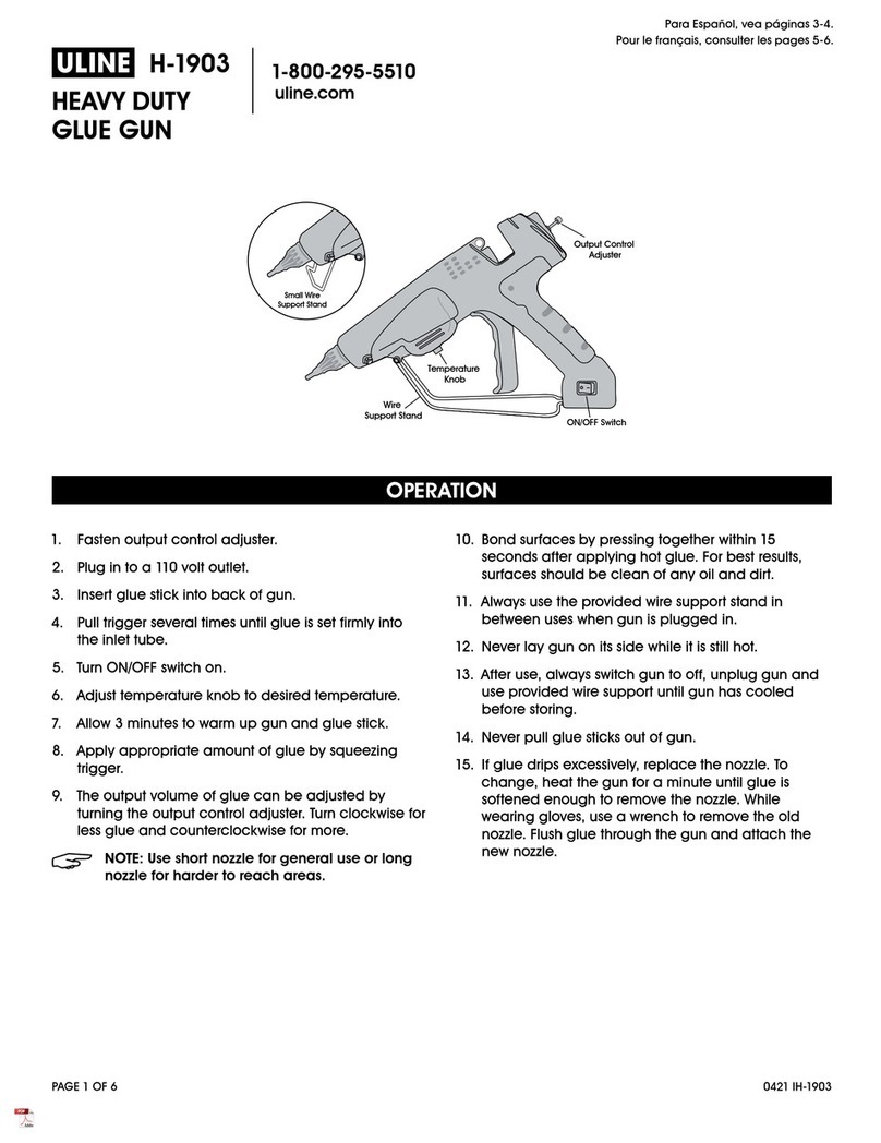
The HP07 is prepared for the manual application of hot melt adhesive or other thermoplastic materials.
The supply of hot melt exclusively takes part via a flexible hose (max. ø of the cap at the end of the hose
44 mm), which is connected with an UES hot melt system.
A heater cartridge and a temperature sensor (Ni 120, PT100, NTC etc.) regulate the temperature of the
handgun independent of the hose and the tank temperature.
When tank, hose and handgun reach the temperatures which were adjusted before, an electronically re-
lease of the pump in the tank takes place. The hot melt adhesive is transported with the before adjusted
pump pressure to the handgun with a gear ratio of 14:1
The HP07 is equipped with a micro switch, with which a gear pump, a bulk melter or an air heater (HP07SP)
can be controlled.
Note! For general directions regarding the operating of hot melt systems please con-
sult the manual for each individual hot melt system.

8
HP 07 Operating Manual
UES AG · Roemerstraße 15 · D-47809 Krefeld
Putting into operation
Check
You acquired a product which left out house in unobjectionable condition.
After unwrapping the HP07 please check the completeness of the delivery (delivery note) and whether
there are damages. Please control whether there is packing material in the ventilation slots of the HP07
which might burn during heating.
Read this manual before putting the handgun into operation.
In case of complains please contact our service to the customer.
Hydraulic connections
Screw the hose using a spanner SW 19 onto the turning nipple. To avoid the turning of the turning nipple
hold it with a spanner SW 19. Before fastening the hose, remount the hose clamp and tighten it.
Should you realise a resistance when tightening the clamp, turn the screw cap of the hose another ¼
turn maximum. Too strong tightening of the hose destroys the sealing surface and the thread of the hose.
Now put the plug of the handgun into the hose connector.
Connect the hose with the hot melt system and supply it with power according to the directions for the
first installation of hot melt systems (Manual UES series compact).
Now switch on the system and adjust, according to the manual of hot melt systems, the temperatures
which are recommended by the adhesive producer.
Plug in hose connector Connection unit hose

HP 07 Operating Manual
9
UES AG · Roemerstraße 15 · D-47809 Krefeld
Release stop
Make sure that the trigger of the handgun is secured. The safety lever is placed at the left side of the HP07.
In secured state the trigger cannot be pulled.
Leave the release stop locked until you get the instruction to loosen it in this manual. That way you avoid
an unintentional release of the handgun.
Start off the system
To start with adjust a low pressure at your hot melt system in order to avoid an uncontrolled leak of hot
melt adhesive.
After reaching the adjusted temperatures please tighten once more all hydraulic screw connections and
fix the enclosed contact protection at the hydraulic connection between hose and HP07 by tightening
the two-piece protection cap at the turning nipple.
Release the trigger by turning the safety lever and slowly pull the trigger. While doing so hold the hand-
gun over a cardboard box or similar case. Adjust now the required quantity of the glue by means of the
regulator at your hot melt appliance. Now you can start your production.
Important! Do never hang up the handgun at the handle but always at the
suspension at the top of the handgun.
HP07 secured HP07 not secured
SuspensionContact protection

10
HP 07 Operating Manual
UES AG · Roemerstraße 15 · D-47809 Krefeld
Handling
Module inset
The HP07 can be provided with three different module types. As standard it is delivered with the module
H300P. This module is technically based upon the UES standard module H300 so the entire UES nozzle
programme for this type of module can be used.
Optional the HP07 can be delivered with the module H300PNA. The model NA (Nadelsitz = needle seat)
offers the following advantages:
• Needle seat with integrated nozzle (0,20 mm – 1,5 mm)
• Special hardened needle seat
• Strong reducing of nozzle obstructions
• Angle hair is reduced to minimum
Using the module H300PSP the HP07 can be developed to a spraying version (refer to „Spraying applica-
tion on page 17).
The difference to spot and bead application (H300P / H300PNA) is that through the diagonal placed integ-
rated air drillings the ray of glue is put into a spiral motion. Hereby an extreme flat, sharp edged and nearly
invisible application is gained, which width and bead size can be individually regulated via air and pump
pressure.
Modules for H300P, H300PNA und H300PSP

HP 07 Operating Manual
11
UES AG · Roemerstraße 15 · D-47809 Krefeld
Change of module
Changing the module please observe the already mentioned safety precau-
tions. The change of modules should only take place in pressure free state
(hydraulic and pneumatic).
Before changing the module of the HP07, release the pressure of the
system.
The following steps have to be carried out:
Put pump pressure to 0 bar.
Screw off the nozzle (H300P/H300PSP).
Place collecting basin below the HP07 in order to avoid pollution
Pull trigger of the HP07 until there does not leak any adhesive out off the handgun any more
Loosen now the glue drain at the tank (see operating instruction Compact) so that no new pressure
can be built up
Turn off the appliance
Loosen the clamping screw with a 4 mm hexagon socket screw key. Pull the trigger to the end and
screw off the clamping screw counter-clockwise.
After having removed the clamping screw out of the service block the trigger can be put back to
normal position. Hereby the module is pushed about 4mm out of the service block and you are able to
pull the module using a pull-out appliance out of the service block.
Check whether the service block is polluted (modul retainer) and clean it if necessary.
Put the new module into the service block and push it leaving a space of about 4mm into the block.
Now pull the trigger and push the module up to stop into the service block.
Retighten the clamping screw. The module now closely abuts on the front side of the service block.
After you have tightened the clamping screw the trigger can be released.
Put the system into operation and after having reached the operating temperature readjust the pump
pressure.
Should you realise that the nozzle has become leaky after several openings and closings, the system
is to be put again into pressure free state and step 7, 11 and 12 have to be repeated.
Change of module
Module
Clamping screw
Pull-out appliance

12
HP 07 Operating Manual
UES AG · Roemerstraße 15 · D-47809 Krefeld
Adjustment of needle stroke
After the exchange of the module it might be necessary to readjust the needle stroke.
Adjust at first a low pressure at your hot melt appliance in order to avoid an uncontrolled
leakage of hot melt adhesive.
Please turn the stroke adjusting screw using a 4mm hexagon socket screw key clockwise (trigger moves
backwards) up to a difference of 0,5 mm between trigger and HP07 housing. When using a hand gun
with electical release (EA) please mind that the micro switch must not audible release.
Readjust the operating pressure and check the needle stroke.
Distance between lever and housing about 0.5 to 1 mm
Stroke adjusting screw
4 mm hexagon socket screw key

HP 07 Operating Manual
13
UES AG · Roemerstraße 15 · D-47809 Krefeld
Maintenance and repair
Should the handgun does not close tightly, the nozzle seat might have become leaky due to wear. In this
case please proceed as explained in chapter „Change of module“.
Mechanical defects
Problem Possible reason Recommendation
Bead is wavy or interrupted Too low temperature Increase temperature
Too low pump pressure Increase pump pressure
glue too old Drain off glue and fill in new one
Nozzle obstructed Replace or clean nozzle
Nozzle too big Install smaller nozzle
Bead too thick or glue splashes
from the substratum
Too high pump pressure Reduce pump pressure
Adhesive is too hot Reduce temperature
Glue forms bubbles Too high temperature Reduce temperature
Tank is empty Refill adhesive
Moisture in the glue or on the
pasteboard
Glue drops out of the gun Needle and/or seat is worn-out
or dirty
Clean and/or replace worn-out
parts
Adjust needle stroke
Frequent nozzle obstructions Glue crusts in the system
(caused by too high temperature,
standstill for some time or dirty
glue store-container)
Clean system, change inline
filters and check tank filter.
Clean or replace nozzles. Check
cause, e.g. too high temperature
in the tank.

14
HP 07 Operating Manual
UES AG · Roemerstraße 15 · D-47809 Krefeld
Electrical defects
In case of a breakdown of heating or sensor, the electric of the HP07 has to be exchanged. The
procedure is as follows;
Release pressure of the system
Disconnect the electrical connection of hose and HP07
Disconnect the hydraulic connection of hose and HP07
Loosen all hexagon socket screws and remove HP07 housing
Disconnect electric and cord set (Pos.6)
Remove the entire service block with trigger and electric out of the housing (Pos.1, 3, 4)
The safety lever has to be put into secured position so that the cable channel is laid open and the
service block with trigger and electric can be taken out of the housing.
Hexagon socket screw
1
3
4
5
6

HP 07 Operating Manual
15
UES AG · Roemerstraße 15 · D-47809 Krefeld
As the HP07 can be connected to different systems (PT100, NI120, NTC etc.) please learn from the ap-
pendix “circuit diagram” for which system your electronic set has to be prepared.
Electric set HP07 (UES/3000) consisting of
Pos.6 Plug
not shown Micro switch (optional for spraying application)
Pos.14 Temperature sensor
Pos.15 Heater cartridge
Pos.16 Earthing cable
Loosen the earthing screw M3X6 using a 2.5 mm hexagon socket screw key (Pos.16)
Pull the sensor and the heating out of the service block (Pos.14, 15)
Exchange the electronic set for a new one and assemble the HP07 in opposite sequence.
During installation please take care that the distance rolls (4 pieces per page) are placed in the ser-
vice block and all cables are in the cable shaft so that no cables are squeezed in when assembling
the HP07.
14
16
15
15
14
16
6

16
HP 07 Operating Manual
UES AG · Roemerstraße 15 · D-47809 Krefeld
Technical appendix
1
2
3
4
5
6
7
89
10
12
13
Parts list
Pos. Description Art.-No.
1Service block
2 Housing L-R
3Trigger
4 Stroke adjusting screw
5Safety lever
6Electronic plug
7 Module H300P 000174
Module H300PNA (0.50 mm) 000181
Module H300PSP 000180
8Clamping screw
9 Suspension
10 Revolving glue nipple 000221
not shown Micro switch (optional for spraying application) Kit
12 Cord set P 000267
Cord set P-EA (electrical) 000266
13 Distance pin

HP 07 Operating Manual
17
UES AG · Roemerstraße 15 · D-47809 Krefeld
Technical Data
Modular system for three types of manual hot melt application:
• Spot/bead - H300 P
• Needle seat - H300 P-NA
• Spraying application - H300 P-SP
The basis body of the gun is the same for all three types. The desired type of handgun is constructed by
exchanging the module and adding extern components.
The storage takes place in construction groups so that the assembly can take place in short time.
Weight 1.15kg with cord set without hose
Measurement 220 x 210 x 38 mm
Voltage 230V AC, 50Hz
Power 150W
Start time 15 min to set temperature
Degree of protection IP22
Housing PA6.6GFK30 heat resistant and isolating
Temperature 200 °C long run, 230 °C short term
Work pressure 40 – 50 bar, short term max. 75 bar
Flowing through without nozzle 0.451/min at 1000mPas
Needle stroke depending on the module 2.4 mm max. linear opening at the entire stroke
Heating transmission of the heat at the entire length of the glue block, 2 sensor positions
for differentiated heating characteristics
Sensor Ni120 or Pt100, FeKo, NTC Dm4-0.05x15 mm cord set length 500 mm
compatible to UES, Nordson®, Meltex®, Robatech®
The standard installation of each handgun includes the electrical release and opening and closing appli-
ance.
Exchange of the module should only take place when the trigger is pulled to the end.
The adjustment of the release depends on the pressure. 0,5mm clearance between housing and trigger
(see drawing 6.3). In this position the switch must not yet be switched.
Through connectors the cord set can be exchanged, e.g. connection of the UES hose for AD31.
The length of the standard needle seat is 40 mm- reaching from glue block to nozzle tip.
The STOP position of the safety lever avoids an unintentional release of the trigger.
Spraying application
For spraying application you need additionally compressed air at your handgun.
• e.g. usage hose with intregrated spray air tube (e.g. 2,4m hose; UES part no. 100292)
• handy appurtenance: Spray air control HP 07 – not operated grip shift switched off the air for the gun
(inline micro switch) (UES article: 100493)

18
HP 07 Operating Manual
UES AG · Roemerstraße 15 · D-47809 Krefeld
Circuit diagram
Index Mat. R. Hofmann Tel. 02151-729555
Blatt
Maflst.
Version Konst.
Datum
Zeichnung unterliegt dem Urheberrecht !
Verfielf‰ltigung und Weitergabe an Dritte
ist strengstens untersagt !
00017711
Schaltplan
E-Installation P UES 01.12.1998
1 von 1
kein
0/0
1
2
3
4
5
6
7
8
1
2
3
4
5
6
7
8
000188 HLP 230V/200W
PTFE-Litze
t∞ 000088 Widerstandsthermometer
Ni120 rot-rot
000169 Mikroschalter
250V/5A blau
Schalter entspannt
gezeichnet =
Pistolenhebel gedr¸ckt
2
1
4Sch
÷ff
Schutzerde an 000209
000170 000171 000170
STI
STI BU
Harting Harting Harting
schwarz
schwarz
rot
rot
weifl
weifl
weifl
gr¸n/gelb

HP 07 Operating Manual
19
UES AG · Roemerstraße 15 · D-47809 Krefeld
Index Mat. R. Hofmann Tel. 02151-729555
Blatt
Maflst.
Version Konst.
Datum
Zeichnung unterliegt dem Urheberrecht !
Verfielf‰ltigung und Weitergabe an Dritte
ist strengstens untersagt !
00017712
Schaltplan
E-Installation P 3000 01.12.1998
1 von 1
kein
0/0
1
2
3
4
5
6
1
2
3
4
5
6
7
8
000188 HLP 230V/200W
PTFE-Litze
t∞ 000088 Widerstandsthermometer
Ni120 rot-rot
000169 Mikroschalter
250V/5A blau
Schalter entspannt
gezeichnet =
Pistolenhebel gedr¸ckt
2
1
4Sch
÷ff
Schutzerde an 000209
000287 000171 000170
STI
BU
Harting Harting
schwarz
schwarz
rot
rot
gr¸n/gelb

20
HP 07 Operating Manual
UES AG · Roemerstraße 15 · D-47809 Krefeld
Index Mat. R. Hofmann Tel. 02151-729555
Blatt
Maflst.
Version Konst.
Datum
Zeichnung unterliegt dem Urheberrecht !
Verfielf‰ltigung und Weitergabe an Dritte
ist strengstens untersagt !
00017713
Schaltplan
E-Installation P Meltex 01.12.1998
1 von 1
kein
0/0
1
2
3
4
5
6
1
2
3
4
5
6
7
8
000188 HLP 230V/200W
PTFE-Litze
t∞ Pt100
000169 Mikroschalter
250V/5A blau
Schalter entspannt
gezeichnet =
Pistolenhebel gedr¸ckt
2
1
÷ff
Schutzerde an 000209
000171 000170
STI
BU
Harting Harting
schwarz
schwarz
rot
rot
gr¸n/gelb
5
5
weifl
weifl
Harting
000170
STI
t∞
+ rot
- blau
FeKo
schwarz-schwarz
Table of contents