4
2.2 HEM10-HK/HEM12-HK HEATER KIT INSTALLATION (without
blower)
This section contains instructions for installing the heater kit for
the HEM10, HEM10-01, HEM12 and HEM12-01 camera
housings. If you are also installing the blower unit, please skip to
page 5 for comprehensive instructions.
While this heater kit is sold as an add-on component for the
HEM10, HEM10-01, HEM12 and HEM12-01, it is also available in
a preassembled package. The HEM10-02 and HEM12-02 are
10- and 12-inch camera housings respectively with an installed
sunshield and heater. The HEM10-03 and HEM12-03 add a
blower kit to this package.
1. If applicable, remove the sunshield by sliding it forward on
the main housing unit.
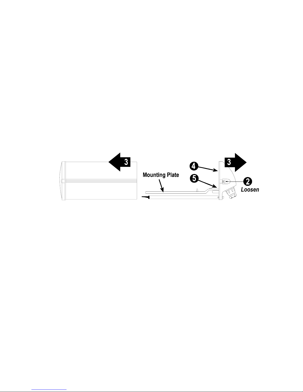
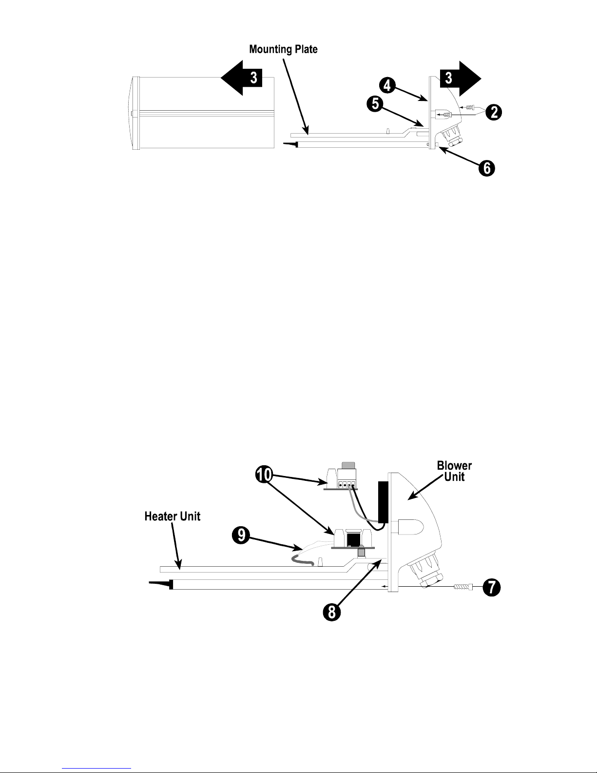
2. Loosen the two Phillips panhead screws located midway up
the rear of the housing unit until they release the body of the
housing. Leave the screws intact in the rear portion of the
housing. (See Figure 4)
3. By sliding the housing shell away from the rear portion of the
unit, separate the housing into two sections. (See Figure 4)
4. Locate the gold, flathead 1/4” x 20 UNC screw and nylon
washer taped to the rear of the housing and set them aside
for later use.
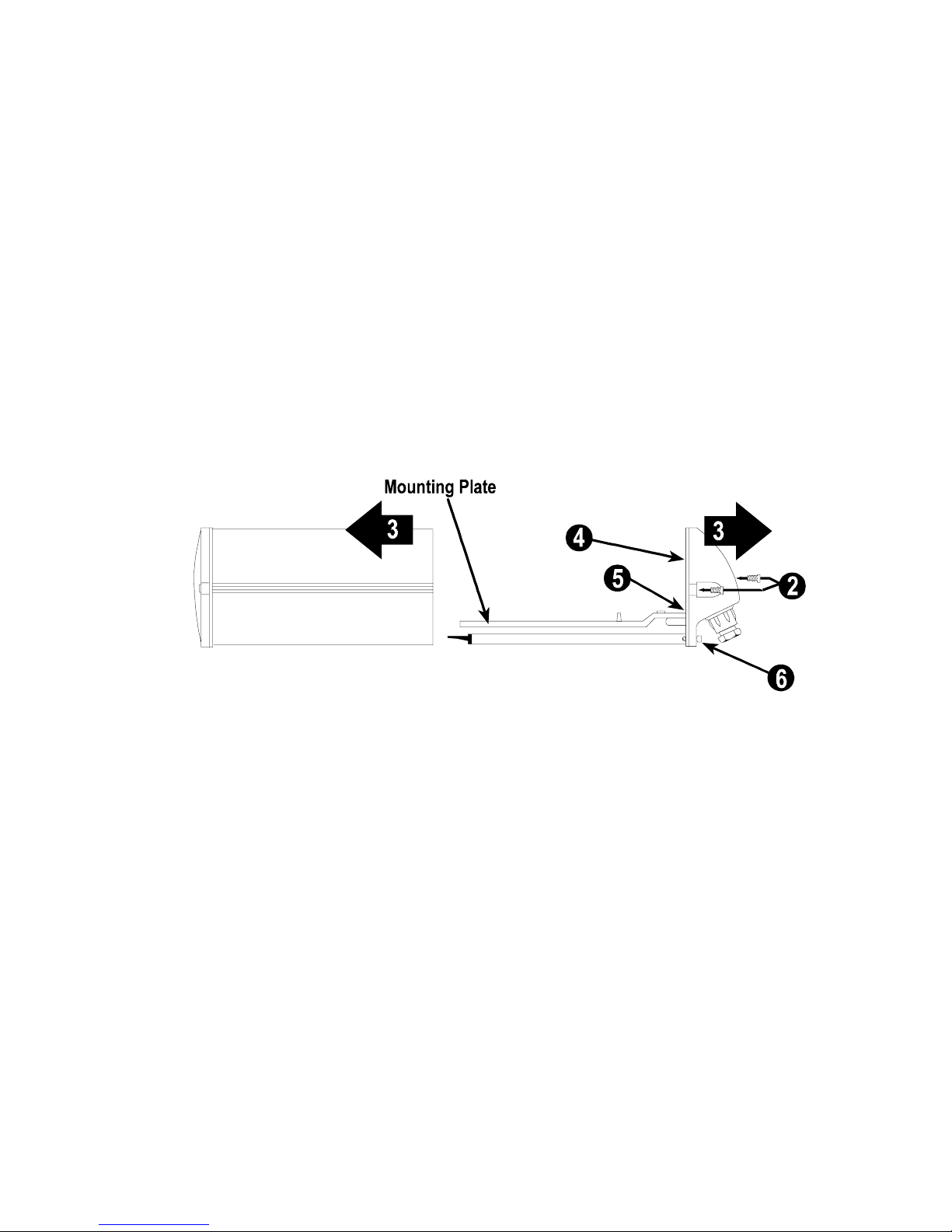
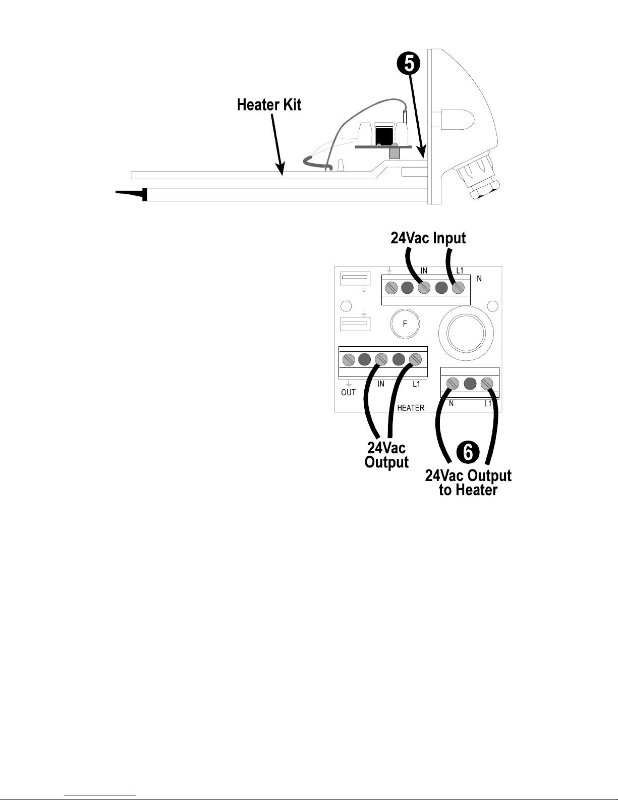
5. Remove the standard silver mounting plate by unscrewing
the flathead Phillips screw located at the rear. Next untape
the gold, flathead 1/4” screw and plastic washer from the
optional mounting plate with built-in heater, and install this
unit in place of the standard mounting plate. Make sure that
the heater plate is secured to the shelf that extends from the
rear of the housing unit. (See Figures 4 & 5)
FIGURE 4