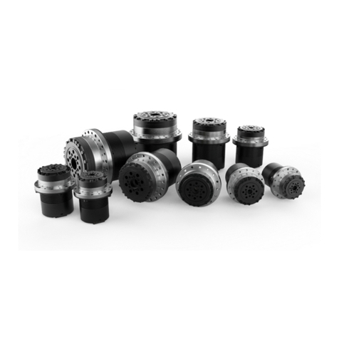
umbratek ADRA HR Series User manual

ADRA ACTUATOR
USER MANUAL
HR / DD Type

EN Ver. 0.2.0
2 / 52 © 2022 Umbratek All Rights Reserved.
Warnings and Note
DANGER
(May cause serious injury or death)
•Never place items containing water, flammables, and solvents near product.
•Never place fingers, arms, toes, and other body parts near product during operation.
•Cut power off if product emits strange odors or smoke.
•Keep product out of reach of children.
•Check the power’s polarity before wiring.
CAUTION
(May cause injury or damage to product)
•Do not operate the product at a temperature exceeding -5 ~ +55 [°C] range.
•Do not insert sharp blades nor pins during product operation.
ATTENTION
(May cause injury or damage to product)
•Do not disassemble or modify product.
•Do not drop or apply strong shock to product.
Limitation of Liability
Any information given in this manual regarding safety must not be construed as a warranty by
Umbratek that the ADRA actuator will not cause injury or damage even if all safety instructions are
complied with.

EN Ver. 0.2.0
3 / 52 © 2022 Umbratek All Rights Reserved.
Catalogue
Warnings and Note_________________________________________________________________________ 2
Catalogue __________________________________________________________________________________ 3
Features ____________________________________________________________________________________ 5
Selection and Specification_________________________________________________________________ 6
Introduction _______________________________________________________________________________ 14
Description________________________________________________________________________________14
Warning ___________________________________________________________________________________14
Packing List _______________________________________________________________________________15
Define of Interface ________________________________________________________________________15
Rotation Direction ________________________________________________________________________17
Status Led_________________________________________________________________________________17
Extended I/O ______________________________________________________________________________17
Umbratek Assistant _______________________________________________________________________ 19
Preparations ______________________________________________________________________________19
Actuator Connection______________________________________________________________________19
Indicator __________________________________________________________________________________21
Position Mode_____________________________________________________________________________22
Speed Mode_______________________________________________________________________________25
Torque Mode______________________________________________________________________________28
Security Parameters ______________________________________________________________________30

EN Ver. 0.2.0
4 / 52 © 2022 Umbratek All Rights Reserved.
Firmware Update _________________________________________________________________________32
Actuator Calibration ______________________________________________________________________33
Other Settings ____________________________________________________________________________35
Software Functions________________________________________________________________________ 36
SDK API____________________________________________________________________________________36
Communication Protocol _________________________________________________________________36
Communication Register _________________________________________________________________36
Advanced API Features ___________________________________________________________________36
Debug COM Data _________________________________________________________________________39
Error Code ________________________________________________________________________________41
Electrical___________________________________________________________________________________ 43
Regenerative Braking Module ____________________________________________________________43
Brake ______________________________________________________________________________________43
Mechanical ________________________________________________________________________________ 44
Mounting__________________________________________________________________________________44

EN Ver. 0.2.0
5 / 52 © 2022 Umbratek All Rights Reserved.
Features
Characteristics
High precision, zero backlash, complete models
Hollow design
Optional light weight, high rigidity or compact harmonic reducer
Drive, brake, servo motor, reducer integrated design (Customizable)
Umbratek Assistant
Online parameter setting
Calibration encoder
Test of each mode
Upgrade firmware online or offline
Real-time graphical curve and data display
Data Bus (RS485/CAN)
Up to 32 actuators can be connected on a Bus
RS485 up to 12us communication response time, up to 11.25Mbps communication rate (adjustable)
RS485 supports broadcast mode at the same time to send instructions to control multiple actuators
RS485 can simultaneously obtain feedback data from multiple actuators in broadcast mode
CAN interface up to 1Mbps communication rate
Development (open source)
SDK (Python, C/C++, C#)
ROS, ROS2
Arduino SDK
STM32 SDK

EN Ver. 0.2.0
6 / 52 © 2022 Umbratek All Rights Reserved.
Selection and Specification
HR Series Model Rule
DD Series Model Rule

EN Ver. 0.2.0
7 / 52 © 2022 Umbratek All Rights Reserved.
HR-A056 Technical Data (L/S Type Flange Reducer)
Ratio
50:1
80:1
100:1
Reducer Type
Light Weight
High Strength
Light Weight
High Strength
Light Weight
High Strength
MAX Torque (N·m)
18
18
23
28
28
35
AVG Torque (N·m)
6.9
9
11
14
11
14
Rated Velocity (RPM)
68
43
34
Inertia (kg·m²)
0.000014
Rated Current (A RMS)
2.5
2.8
2.1
2.6
2.0
2.5
MAX Current (A RMS)
5.2
6.0
4.6
5.8
4.5
5.5
Weight - Brake (g)
790
990
790
990
790
990
Weight - No Brake (g)
695
895
695
895
695
895
Size (mm)
Motor d56, Flange D73, Height H86, Hole 7
Power Voltage
Rated DC48V (Operating Range DC19-52V)
Backup Battery
16bit Encoder Battery DC3V, 19bit Encoder Battery DC3.6V
Standby Current
Driver < 35mA, Encoder Battery < 2.9uA
Pole Pairs
7
Backlash
±0.007° (±25 Arcsec)
Encoder & Resolution
Multi-turn Absolute Magnetic Encoder, 65536 x Ratio (16bit) / 524288 x Ratio (19bit) Pulse/Rev.
Interfaces
RS485 / CAN / Pulse / EtherNet (Add an External Module)
Feedback
Position / Speed / Current / Voltage / Temperature
Operating Mode
Torque / Velocity / Position
Safety Design
Overload Protection, Over/Low voltage Protection, Temperature Protection, ESD Protection,
Torque / Velocity / Position Protection
Materials
Aviation Aluminum, Steel
Ambient Conditions
Operation 5 to 40℃, Storage 0 to 45℃, Humidity 20 to 75% (non-condensing)
Protection Rating
IP30

EN Ver. 0.2.0
8 / 52 © 2022 Umbratek All Rights Reserved.
HR-A063 Technical Data (L/S Type Flange Reducer)
Ratio
50:1
80:1
100:1
Reducer Type
Light Weight
High Strength
Light Weight
High Strength
Light Weight
High Strength
MAX Torque (N·m)
34
35
43
56
54
70
AVG Torque (N·m)
26
34
27
35
39
51
Rated Velocity (RPM)
50
31
25
Inertia (kg·m²)
0.000028
Rated Current (A RMS)
5.2
5.5
4.1
5.3
4.0
5.2
MAX Current (A RMS)
10.9
11.5
8.6
11.2
8.5
11.0
Weight - Brake (g)
1030
1250
1030
1250
1030
1250
Weight - No Brake (g)
900
1120
900
1120
900
1120
Size (mm)
Motor d63, Flange D79, Height H94, Hole 7
Power Voltage
Rated DC48V (Operating Range DC19-52V)
Backup Battery
16bit Encoder Battery DC3V, 19bit Encoder Battery DC3.6V
Standby Current
Driver < 35mA, Encoder Battery < 2.9uA
Pole Pairs
10
Backlash
±0.007° (±25 Arcsec)
Encoder & Resolution
Multi-turn Absolute Magnetic Encoder, 65536 x Ratio (16bit) / 524288 x Ratio (19bit) Pulse/Rev.
Interfaces
RS485 / CAN / Pulse / EtherNet (Add an External Module)
Feedback
Position / Speed / Current / Voltage / Temperature
Operating Mode
Torque / Velocity / Position
Safety Design
Overload Protection, Over/Low voltage Protection, Temperature Protection, ESD Protection,
Torque / Velocity / Position Protection
Materials
Aviation Aluminum, Steel
Ambient Conditions
Operation 5 to 40℃, Storage 0 to 45℃, Humidity 20 to 75% (non-condensing)
Protection Rating
IP30

EN Ver. 0.2.0
9 / 52 © 2022 Umbratek All Rights Reserved.
HR-A072 Technical Data (L/S Type Flange Reducer)
Ratio
50:1
80:1
100:1
120:1
Reducer Type
Light
Weight
High
Strength
Light
Weight
High
Strength
Light
Weight
High
Strength
Light
Weight
High
Strength
MAX Torque (N·m)
50
50
74
80
82
100
87
110
AVG Torque (N·m)
34
44
47
61
49
64
49
64
Rated Velocity (RPM)
40
25
20
17
Inertia (kg·m²)
0.000061
Rated Current (A RMS)
7.4
7.6
6.9
7.4
6.0
7.3
5.5
6.9
MAX Current (A RMS)
15.6
15.8
14.6
15.5
12.7
15.4
11.5
14.6
Weight - Brake (g)
1450
1790
1450
1790
1450
1790
1450
1790
Weight - No Brake (g)
1275
1615
1275
1615
1275
1615
1275
1615
Size (mm)
Motor d72, Flange D93, Height H101, Hole 10
Power Voltage
Rated DC48V (Operating Range DC19-52V)
Backup Battery
16bit Encoder Battery DC3V, 19bit Encoder Battery DC3.6V
Standby Current
Driver < 35mA, Encoder Battery < 2.9uA
Pole Pairs
10
Backlash
±0.007° (±25 Arcsec)
Encoder & Resolution
Multi-turn Absolute Magnetic Encoder, 65536 x Ratio (16bit) / 524288 x Ratio (19bit) Pulse/Rev.
Interfaces
RS485 / CAN / Pulse / EtherNet (Add an External Module)
Feedback
Position / Speed / Current / Voltage / Temperature
Operating Mode
Torque / Velocity / Position
Safety Design
Overload Protection, Over/Low voltage Protection, Temperature Protection, ESD Protection,
Torque / Velocity / Position Protection
Materials
Aviation Aluminum, Steel
Ambient Conditions
Operation 5 to 40℃, Storage 0 to 45℃, Humidity 20 to 75% (non-condensing)
Protection Rating
IP30

EN Ver. 0.2.0
10 / 52 © 2022 Umbratek All Rights Reserved.
HR-A086 Technical Data (L/S Type Flange Reducer)
Ratio
50:1
80:1
100:1
120:1
160:1
Reducer Type
Light
Weight
High
Strength
Light
Weight
High
Strength
Light
Weight
High
Strength
Light
Weight
High
Strength
Light
Weight
High
Strength
MAX Torque (N·m)
98
100
137
160
157
200
167
217
176
229
AVG Torque (N·m)
55
72
87
113
108
140
108
140
108
140
Rated Velocity (RPM)
40
25
20
17
13
Inertia (kg·m²)
0.000181
Rated Current (A RMS)
14.5
15.0
12.6
14.7
11.5
14.6
10.4
13.5
8.1
10.5
MAX Current (A RMS)
30.1
31.7
26.6
31.0
24.2
31.0
22.0
28.5
17.1
22.2
Weight - Brake (g)
2800
3200
2800
3200
2800
3200
2800
3200
2800
3200
Weight - No Brake (g)
2500
2900
2500
2900
2500
2900
2500
2900
2500
2900
Size (mm)
Motor d86, Flange D107, Height H136, Hole 10
Power Voltage
Rated DC48V (Operating Range DC38-52V)
Backup Battery
16bit Encoder Battery DC3V, 19bit Encoder Battery DC3.6V
Standby Current
Driver < 35mA, Encoder Battery < 2.9uA
Pole Pairs
10
Backlash
±0.007° (±25 Arcsec)
Encoder & Resolution
Multi-turn Absolute Magnetic Encoder, 65536 x Ratio (16bit) / 524288 x Ratio (19bit) Pulse/Rev.
Interfaces
RS485 / CAN / Pulse / EtherNet (Add an External Module)
Feedback
Position / Speed / Current / Voltage / Temperature
Operating Mode
Torque / Velocity / Position
Safety Design
Overload Protection, Over/Low voltage Protection, Temperature Protection, ESD Protection,
Torque / Velocity / Position Protection
Materials
Aviation Aluminum, Steel
Ambient Conditions
Operation 5 to 40℃, Storage 0 to 45℃, Humidity 20 to 75% (non-condensing)
Protection Rating
IP30

EN Ver. 0.2.0
11 / 52 © 2022 Umbratek All Rights Reserved.
HR-A113 Technical Data (L/S Type Flange Reducer)
Ratio
50:1
80:1
100:1
120:1
160:1
Reducer Type
Light
Weight
High
Strength
Light
Weight
High
Strength
Light
Weight
High
Strength
Light
Weight
High
Strength
Light
Weight
High
Strength
MAX Torque (N·m)
210
210
304
330
333
420
353
450
372
480
AVG Torque (N·m)
108
140
167
217
216
281
216
281
216
281
Rated Velocity (RPM)
30
19
15
13
10
Inertia (kg·m²)
0.000546
Rated Current (A RMS)
26.0
26.0
23.5
25.5
20.0
25.0
18.2
23.2
14.8
19.0
MAX Current (A RMS)
53.5
53.5
50.0
52.5
41.9
52.0
38.4
49.0
31.0
40.2
Weight - Brake (g)
4800
5800
4800
5800
4800
5800
4800
5800
4800
5800
Weight - No Brake (g)
4400
5400
4400
5400
4400
5400
4400
5400
4400
5400
Size (mm)
Motor d113, Flange D138, Height H147, Hole 10
Power Voltage
Rated DC48V (Operating Range DC38-52V)
Backup Battery
19bit Encoder Battery DC3.6V
Standby Current
Driver < 35mA, Encoder Battery < 2.9uA
Pole Pairs
14
Backlash
±0.007° (±25 Arcsec)
Encoder & Resolution
Multi-turn Absolute Magnetic Encoder, 524288 x Ratio (19bit) Pulse/Rev.
Interfaces
RS485 / CAN / Pulse / EtherNet (Add an External Module)
Feedback
Position / Speed / Current / Voltage / Temperature
Operating Mode
Torque / Velocity / Position
Safety Design
Overload Protection, Over/Low voltage Protection, Temperature Protection, ESD Protection,
Torque / Velocity / Position Protection
Materials
Aviation Aluminum, Steel
Ambient Conditions
Operation 5 to 40℃, Storage 0 to 45℃, Humidity 20 to 75% (non-condensing)
Protection Rating
IP30

EN Ver. 0.2.0
12 / 52 © 2022 Umbratek All Rights Reserved.
HR-A055/A062/A071 Technical Data (C Type Compact Reducer)
Model
HR-A055
HR-A062
HR-A071
Reducer Type
Compact Type, Non-hollow and Flange
Ratio
50:1
100:1
50:1
100:1
50:1
100:1
MAX Torque (N·m)
12
19
23
37
39
57
AVG Torque (N·m)
4.8
7.7
18
27
24
34
Rated Velocity (RPM)
70
35
52
26
44
22
Rated Current (A RMS)
1.1
1.5
2.0
3.0
3.5
4.4
MAX Current (A RMS)
2.2
3.2
4.2
6.3
7.2
9.3
Inertia (kg·m²)
0.000014
0.000028
0.000061
Weight - Brake (g)
770
1000
1415
Weight - No Brake (g)
675
870
1240
Size D x H (mm)
55 x 80
62 x 86
71 x 96
Pole Pairs
7
10
10
Power Voltage
Rated DC48V (Operating Range DC38-52V)
Backup Battery
16bit Encoder Battery DC3V, 19bit Encoder Battery DC3.6V
Standby Current
Driver < 35mA, Encoder Battery < 2.9uA
Backlash
±0.007° (±25 Arcsec)
Encoder & Resolution
Multi-turn Absolute Magnetic Encoder, 65536 x Ratio (16bit) / 524288 x Ratio (19bit) Pulse/Rev.
Interfaces
RS485 / CAN / Pulse / EtherNet (Add an External Module)
Feedback
Position / Speed / Current / Voltage / Temperature
Operating Mode
Torque / Velocity / Position
Safety Design
Overload Protection, Over/Low voltage Protection, Temperature Protection, ESD Protection,
Torque / Velocity / Position Protection
Materials
Aviation Aluminum, Steel
Ambient Conditions
Operation 5 to 40℃, Storage 0 to 45℃, Humidity 20 to 75% (non-condensing)
Protection Rating
IP30

EN Ver. 0.2.0
13 / 52 © 2022 Umbratek All Rights Reserved.
DD-A Series Technical Data (Direct Drive Actuator)
Model
A055
A056
A062
A063
A071
A072
A085
A086
A112
A113
MAX Torque (N·m)
1.10
2.50
2.70
5.90
8.35
AVG Torque (N·m)
0.35
0.70
1.00
2.50
4.80
Rated Velocity (RPM)
3500
2600
2200
2000
1500
Inertia (kg·m²)
0.000012
0.000023
0.000049
0.000150
0.000437
Rated Current (A RMS)
2.5
5.2
7.3
14.6
25
MAX Current (A RMS)
5.3
11.0
15.4
30.8
52.7
Torque Constant
(N·m / A)
0.0743
0.106
0.109
0.148
0.128
Pole Pairs
7
10
10
10
14
Weight - Brake (g)
417
420
540
539
763
765
1667
1680
2487
2500
Weight - No Brake (g)
322
325
410
409
588
590
1377
1390
2097
2110
Size (mm)
d55
H57
d56/D73
H54
d62
H62
d63/D79
H58
d71
H68
d72/D93
H64
d85
H95
d86/D107
H90
d112
H96.3
d113/D138
H91
Hole Diameter (mm)
7
7
10
10
10
Axial/Radial Load (kN)
1.26/1.26
1.26/1.26
2.47/2.47
2.95/2.95
2.95/2.95
Power Voltage
Rated DC48V (Range DC19-52V)
Rated DC48V (Range DC38-52V)
Backup Battery
16bit Encoder Battery DC3V, 19bit Encoder Battery DC3.6V
Standby Current
Driver < 35mA, Encoder Backup Battery < 2.9uA
Encoder & Resolution
Multi-turn Absolute Magnetic Encoder, 65536 (16bit) / 524288 (19bit) Pulse/Rev.
Interfaces
RS485 / CAN / Pulse / EtherNet (Add an External Module)
Feedback
Position / Speed / Current / Voltage / Temperature
Operating Mode
Torque / Velocity / Position
Safety Design
Overload Protection, Over/Low voltage Protection, Temperature Protection, ESD Protection,
Torque / Velocity / Position Protection
Materials
Aviation Aluminum, Steel
Ambient Conditions
Operation 5 to 40℃, Storage 0 to 45℃, Humidity 20 to 75% (non-condensing)
Protection Rating
IP30

EN Ver. 0.2.0
14 / 52 © 2022 Umbratek All Rights Reserved.
Introduction
Description
Each ADRA Actuator is built to last and comes with a high-precision harmonic reducer made of
high-strength aviation aluminum and high-carbon chromium steel. A high-torque density, and
compact structure, enable the motor to be integrated into the actuator and lessens the actuator
weight.
Actuator integrated design, also equipped with brake, off-axis multi-turn absolute encoder,
high-performance driver, FOC controller and ADRC controller. with DC bus over-voltage, DC bus
under-voltage, current overload, motor over-temperature, motor under-temperature, reverse
connection, short circuit, blocking and other protection functions.
Warning
1. Do not charge the battery.
2. Ensure all the cables are properly connected
3. Ensure the actuator is securely mounted
4. Avoid damage to the cables or wires, as it may negatively affect the performance.
5. The temperature of motor would keep rising when the output torque is high. Although this is
normal, take caution to avoid overheating
6. Please use the actuator strictly in accordance with the operating environment and the maximum
allowable temperature range specified in this document
7. DO NOT disassemble the actuator, as this may negatively affect the accuracy of the motor and
may lead to permanent malfunction.

EN Ver. 0.2.0
15 / 52 © 2022 Umbratek All Rights Reserved.
2. Power Cable (Red) x1
3. Power Cable (Black) x1
4. Dual-plug Data Cable x1
5. Single-plug Data Cable x1
6. Backup Battery x1
8. Always keep the actuator away from strong magnetic environment, iron products and other
magnetic materials when installing or using, otherwise the actuator may start to vibrate violently.
9. Store the actuator and accessories in a dry, ventilated and clean environment under room
temperature.
10. Avoid impact and dramatic vibration during transportation, loading and unloading.
Packing List
Define of Interface

EN Ver. 0.2.0
16 / 52 © 2022 Umbratek All Rights Reserved.
Power Interfaces
Connect the actuator to a DC48V power supply through power cables. Each actuator integrates double
power supply interface, multiple actuators can be used in series. The cable diameter (Conductor) of
the interface is 2.5mm.
RS485/CAN Interfaces
Connect the RS485/CAN interface to the external control device through signal cable. Through
RS485/CAN, the external control device can send control instructions to the actuator and get feedback
from the actuator. The default baud rate for the RS485 bus is 921600bps, and the default baud rate
for the CAN bus is 1Mbps. Each actuator has two parallel interfaces, and multiple actuators can be
used in series. The model of the interface seat is BM03B-GHS-TBT.
Battery Interfaces
Through this interface, an external battery can be used to power the multi-turn encoder. Note that you
need to use Umbratek Assistant to calibrate the encoder every time you plug in the battery (Assistant
will automatically prompt you to connect the actuator, just follow the prompts). The model of the
interface seat is BM02B-GHS-TBT.
Extend I/O Interfaces
The extended I/O port provides pulse signal control and high-speed debugging data output. For
details, see "Extended I/O". The type of the interface seat is SM05B-SURS-TF, and can be connected
using a type 05SUR-32S connector.
Indicator LED
Indicates the current status of the actuator. See "Indicator" for details.
Power Cable
Red: +48V
Black: GND
RS485/CAN Cable
Connector type: GHR-03V-S (pitch 1.25mm 3Pin)

EN Ver. 0.2.0
17 / 52 © 2022 Umbratek All Rights Reserved.
Rotation Direction
Direction of actuator rotation
When viewed from the top of the output axis: counterclockwise rotation (CCW) is called the positive
direction (+) and clockwise rotation (CW) is called the reverse direction (-).
Status LED
The status LED is used to indicate the operational status of the motor. Note: the driver automatically
cuts off the output stream when it is in abnormal status.
Indicator
Status
Description
Breathing
Normal
Standby
Always on
Normal
Enabled
Blinks 3Hz
Fault
Error, check error code
Blinks 10Hz
Normal
Boot mode
Extended I/O
The interfaces are IO1, IO2, RX, TX and GND from left to right. Note that the extended I/O is an I/O
with a TTL level of 3.3~5V. Different modes have different functions as well as input and output
features.
1. Pulse Position Mode (Not released yet, need to update the firmware)
IO1: TTL input mode, controls the actuator movement direction. High level is in the positive direction
and low level is in the opposite direction.
IO2: TTL input mode, controls the actuator movement Angle. Each pulse movement 360/65535
degrees.

EN Ver. 0.2.0
18 / 52 © 2022 Umbratek All Rights Reserved.
RX: TTL input mode, controls actuator enable status. High level enables actuator, low level disables
actuator.
TX: TTL output mode, debugging information output serial port. For details, see “debugging COM
Information”.
2. Position/Speed/Torque Mode (Not released yet, need to update the firmware)
IO1: TTL output mode, encoder ABZ output phase A.
IO2: TTL output mode, encoder ABZ output phase B.
RX: TTL output mode. High level indicates that the actuator is enabled, and low level indicates that the
actuator is disabled.
TX: TTL output mode. debugging information output serial port. For details, see “debugging COM
Information”.
3. Debug Mode (Not released yet, need to update the firmware)
IO1: TTL output mode, test the current sampling time of the current loop. High level indicates the start
of sampling, low level indicates the end of sampling.
IO2: TTL output mode, test the calculation start and end time of position/speed loop. High level
indicates the start of calculation, low level indicates the end of calculation.
RX: TTL output mode, test the encoder sampling time. High level indicates the start of sampling, low
level indicates the end of sampling.
TX: TTL output mode. debugging information output serial port. For details, see “debugging COM
Information”.

EN Ver. 0.2.0
19 / 52 © 2022 Umbratek All Rights Reserved.
Umbratek Assistant
Preparations
As an app dedicatedly designed for Umbratek Components. Compatible with the ADRA Series, FLXI
Series, Communication Modules and more. Umbratek Assistant is compatible with a variety of
operating systems, including Windows, MacOS and Linux.
1. Download and install Umbratek Assistant from the official website:
https://www.umbratek.com/download-center
2. Select a tool based on the interface type of the actuator (USB-RS485 / USB-CAN / EtherNet-RS485 /
EtherNet-CAN), connect the actuator to the computer. DataLink series high-speed modules are
available from Umbratek
3. Start Umbratek Assistant
4. Scan and connect the ADRA actuator to enter the control interface, see “actuator connection”for
details
5. Use Assistant to test, tune, calibrate, or upgrade the actuator, as described in the following sections.
Actuator Connection
1. Select USB or EtherNet to connect the communication device to the computer. (Figure: Assistant
connection interface 1)
2. Click "Scan", the software will automatically identify the computer port, actuator ID, actuator baud
rate. When the actuator is identified, it will be displayed in a list. The ID, port, and baud rate of the
interface will also be automatically set. (Figure: Assistant connection interface 2)
3. Click Connect to connect the first actuator in the list.
Note: If you use the encoder battery for the first time or replace/plug the encoder battery for the first

EN Ver. 0.2.0
20 / 52 © 2022 Umbratek All Rights Reserved.
time, you will be reminded that the multi-turn encoder is abnormal when connecting to Assistant. You
only need to calibrate the encoder as prompted by the software, and power on the actuator again
after calibration.
Assistant Connection Interface 1
Assistant Connection Interface 2
This manual suits for next models
1
Table of contents
Other umbratek Controllers manuals