umbratek ADRA Series User manual

Version 0.1.0
!
ADRA SERIES
HR TYPE ACTUATORS
USER MANUAL
Date: SEP 2021
Version: 0.1.0
1
© 2021 umbratek. All rights reserved.

Version 0.1.0
1 Introduction
t
1.1 Warnings and Note!
DANGER"
(May cause serious injury or death)!
•Never place items containing water, flammables, and solvents near product.
•Never place fingers, arms, toes, and other body parts near product during
operation.
•Cut power off if product emits strange odors or smoke.
•Keep product out of reach of children.
•Check the power’s polarity before wiring.
CAUTION"
(May cause injury or damage to product)!
•Do not operate the product at a temperature exceeding -5 ~ +55 [°C] range.
•Do not insert sharp blades nor pins during product operation.
ATTENTION"
(May cause injury or damage to product)!
•Do not disassemble or modify product.
•Do not drop or apply strong shock to product.
1.2 Limitation of Liability!
Any information given in this manual regarding safety must not be construed as a
warranty by Umbratek that the ADRA actuator will not cause injury or damage even if all
safety instructions are complied with.#
2
© 2021 umbratek. All rights reserved.

Version 0.1.0
2 Product Description!
2.1 Overview of the ADRA Actuator !
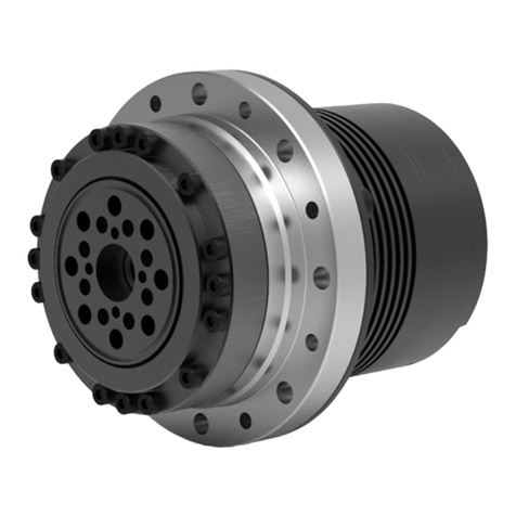
A ADRA Actuator comprises all the assemblies of a servo system, including the
actuator (integrated mechanical system and electrical installations), power cables,
communication cables and encoder backup battery.
The servo system consists of the following components:
•Actuator
•Power cables
•Communication cables
•Encoder backup battery
•Software
•Options, accessories
3
© 2021 umbratek. All rights reserved.

Version 0.1.0
3 Technical Data!
3.1 Overview of the ADRA HR Type Actuators!
BASIC DATA
* Measured at 1:100 ratio.
HR-A56
HR-A63
HR-A72
HR-A86
HR-A113
VOLTAGE
Rated 48V (Range 19-52V)
Rated 48V (Range 38-52V)
RATED POWER
100W
250W
300W
600W
1200W
MAX TORQUE*
35N.m
70N.m
100N.m
200N.m
400N.m
AVG TORQUE*
12N.m
45N.m
55N.m
120N.m
250N.m
VELOCITY*
34RPM
25RPM
20RPM
20RPM
18RPM
CURRENT*
2.5A
5.2A
7.3A
14.6A
25A
STANDBY CURRENT
Driver < 35mA, Backup battery <2.9uA
POLE PAIRS
7
10
10
10
14
SIZE (d/DxH)
56/73x86
63/79x94
72/93x101
86/107x136
113/138x147
WEIGHT
790g
1030g
1450g
2800g
4800g
RATIO
1:30/50/80/100/120 (default 1:100)
1:50/80/100/120/160
BACKLASH
±0.007° (±25 Arcsec)
ENCODER
16 bit multi-turn absolute magnetic encoder
RESOLUTION*
52428800 / 6553600 Pulse/Rev (Optional)
INTERFACES
Pulse, RS485 or CAN, EtherNet (Add an external module)
FEEDBACK
Position / Speed / Current / Voltage / Temperature
OPERATING MODE
Torque / Velocity / Position
SAFETY DESIGN
Overload protection, Over/Low voltage protection, Reverse connection protection,
Temperature protection, ESD protection
MATERIALS
Aluminum, Steel
AMBIENT
CONDITIONS
Operation 5 to 40℃, Storage 0 to 45℃, Humidity 20 to 75%
PROTECTION
RATING
IP30
4
© 2021 umbratek. All rights reserved.

Version 0.1.0
3.2 Model Number Definition!
Example. HR-A56-35-100-RN-HBN
5
© 2021 umbratek. All rights reserved.
ADRA Series HR-Type Actuator
Product Type
Diam.(mm)
Max
Torque
(N.m)
Ratio
Interface
Encoder Type
Shaft Type
Brake
Torque
Sensor
A
Light-weight
Standard Type
(Cup Type FlexSpline)
56
D73
d56
15
30
R
RS485
P
Precision
H
Hollow
Shaft
B
Brake
T
Torque
Sensor
B
Standard Type
(Cup Type FlexSpline)
63
D79
d63
25
50
C
CAN
N
Normal
S
Solid
Shaft
N
Without
Brake
N
Without
Sensor
C
Slim Type
(Cup Type FlexSpline)
72
D93
d72
35
80
E
EtherCAT
D
Flat Type
(Hat Type FlexSpline)
86
D107
d86
45
100
N
EtherNet
E
Flat Type Lite
(Hat Type FlexSpline)
113
D138
d113
70
120
100
160
200
400

Version 0.1.0
4 Install!
4.1 Connecting Cables and Interfaces!
Dual power supply and dual communication bus interfaces are integrated on the
wiring panel, and multiple intelligent actuators are connected at the same time and
can be used in series.
The expansion interface is used for future function upgrades. Can provide traditional
pulse signal drive, and integrate a high-speed serial interface for function expansion.
Note: This interface is TTL level, and electrical signal conversion may be required when using it.
6
© 2021 umbratek. All rights reserved.
GND GND48V 48V
Backup Battery
INDICATOR
GND
RS485B
RS485A
GND
DC3V
RS485/CAN
Power Interface
I
IO1 IO2 RX TX GND
Expansion Interface

Version 0.1.0
The diagram below shows the serial connection of the bus.
5 Software!
5.1 Umbratek Assistant
Umbratek Assistant is compatible with a variety of operating systems, including
Windows, MacOS and Linux.
Download and install Umbratek Assistant from the official website:
https://www.umbratek.com/download-center
-Install Umbratek Assistant
-Connect to USB interface of computer through USB to RS485 communication
module (some computers need driver support)
-Start Umbratek Assistant
-Scan and connect the ADRA actuator to enter the control interface.
7
© 2021 umbratek. All rights reserved.
Terminal Res.
EtherNet / PCIe / USB
Motion Controller
PC + Communication Module
or
11.25Mbps
Actuator 1
Actuator 2
Actuator n

Version 0.1.0
Start Page
-Start the actuator and release the brake protection through the Enable and Brake
buttons in the upper right corner of the page.
-Select control mode.
-Adjust parameters based on actual conditions.
Adjustable Parameter Page
8
© 2021 umbratek. All rights reserved.

Version 0.1.0
Assist parameter setting by oscilloscope
5.2 ADRA Actuators API!
The ADRA family of actuators API documentation can be viewed on the Wiki page.
Python, C, C++, C# and Arduino versions are currently available, and the code will
continue to be updated on Github.
Wiki https://umbratek.com/wiki/en/#!adra/adra_api_python.md
GitHub https://github.com/umbratek
5.3 ADRA Actuators Protocol!
ADRA series actuators support standard RS485 and CAN electrical interfaces.
The RS485 port uses the UTRC protocol, and the CAN port uses the UTCC protocol.
More information can be found on the Wiki.
UTRC https://umbratek.com/wiki/en/#!adra/utrc_communication_protocol.md
UTCC https://umbratek.com/wiki/en/#!adra/utcc_communication_protocol.md
9
© 2021 umbratek. All rights reserved.

Version 0.1.0
5.4 ADRA Actuators Register!
The register and Control Table Description are available on the wiki.
https://umbratek.com/wiki/en/#!adra/adra_communication_register.md
5.4 ADRA Actuators Control Algorithms!
ADRA series actuators support ADRC (Active Disturbance Rejection Controller) and
PID (Proportion Integration Differentiation) closed-loop control algorithms, and all
support current, speed and position control modes. The factory default is ADRC
control algorithm, the following is about the algorithm control block diagram.
Below figure is a block diagram describing the position controller in Position Control
Mode and Extended Position Control Mode. When the instruction is received by the
device, it takes following steps until driving the device.
ESO (Extended State Observer), TD (Tracking Differentiator)
Below figure is a block diagram describing the velocity controller in Velocity Control
Mode. When the instruction is received by the device, it takes following steps until
driving the device.
ESO (Extended State Observer), TD (Tracking Differentiator)
10
© 2021 umbratek. All rights reserved.

Version 0.1.0
Below figure is a block diagram describing the current controller in Current Control
Mode. When the instruction is received by the device, it takes following steps until
driving the device.
Below figure is a block diagram describing the ADRC Current in Current Loop. This
loop works in all modes.
11
© 2021 umbratek. All rights reserved.

Version 0.1.0
6 Mounting!
6.1 Overall Dimensions!
The 3D model of this product can be downloaded from the official website:
https://www.umbratek.com/download-center
6.2 HR-A56 Dimensions
HR-A56 Dimension
12
© 2021 umbratek. All rights reserved.
P.C.D Φ23
6-M4 8
Φ11 H7
P.C.D Φ65
4- Φ7
+0.20
0
8- Φ4.50 Thru-hole Φ7
89.75
9.50
Φ56 h7
Φ56 h7
4
+0.20
0
4
27
50.85

Version 0.1.0
6.3 HR-A63 Dimensions!
HR-A63 Dimension
13
© 2021 umbratek. All rights reserved.
97.25
29
Φ63 h7
Φ63 h7
10.50
4
55.35
4
+0.20
0
Φ10 H7
6-M5 10
P.C.D Φ71 P.C.D Φ27
4- Φ7
+0.20
0
8- Φ4.50 Thru-hole Φ7

Version 0.1.0
6.4 HR-A72 Dimensions!
HR-A72 Dimension
14
© 2021 umbratek. All rights reserved.
P.C.D Φ32
Φ14 H7
8-M6 10
P.C.D Φ82
4- Φ8.50
+0.20
0
8-Φ5.50 Thru-hole Φ10
Φ72 h7
Φ72 h7
28
6
5
+0.20
0
104.25
12.5061.35

Version 0.1.0
6.5 HR-A86 Dimensions!
HR-A86 Dimension
15
© 2021 umbratek. All rights reserved.
P.C.D Φ42
Φ20 H7
8-M8 12
P.C.D Φ96
Φ10
10- Φ5.50 Thru-hole
5- Φ8.50
+0.20
0
36
5
86.90 13
135.90
5
+0.20
0
Φ86 h7
Φ86 h7

Version 0.1.0
6.6 HR-A113 Dimensions!
HR-A113 Dimension
16
© 2021 umbratek. All rights reserved.
P.C.D Φ55
Φ26 H7
8-M10 12
P.C.D Φ125
Φ10
4- Φ10
+0.20
0
12- Φ6.40 Thru-hole
45
146.90
86.40 15.50
6.20
+0.20
0
5
Φ113 h7
Φ113 h7
Table of contents
Other umbratek Controllers manuals